Departamento de Ciências e Tecnologias de Informação
Mesh Networks for Handheld Mobile Devices
Carlos José Pereira da Silva Meralto
Dissertação submetida como requisito parcial para obtenção do grau de
Mestre em Engenharia de Telecomunicações e Informática
Orientador(a):
Prof. Rui Neto Marinheiro, Professor Auxiliar,
ISCTE-Instituto Universitário de Lisboa
Coorientador(a):
Prof. José Moura, Professor Auxiliar,
ISCTE-Instituto Universitário de Lisboa
Abstract
Mesh communications emerge today as a very popular networking solution. Mesh networks have a decentralized and multihop design. These characteristics arouse interest in research for relevant novel features, such as cooperation among nodes, distribution of tasks, scalability, communication with limited infrastructure support, and the support of mobile devices as mesh nodes.
In addition to the inexistence of a solution that implements mesh networks with mobile devices at the data link layer (Layer 2), there is also a need to reconsider existing metrics with new information to tackle the intrinsic characteristics of mobile devices, e.g., the limited energy resources of their battery.
To tackle this problem, this thesis presents a detailed study about projects, routing protocols and metrics developed in the area of mesh networks. In addition, two data link layer solutions, Open802.11s and B.A.T.M.A.N-advanced, have been adapted and deployed in a real mesh network testbed with off the shelf routers devices installed with a customized operating system. From this testbed, Open802.11s has proved to offer better performance than B.A.T.M.A.N-advanced. Following this, a breakthrough in this work has been the integration of the 802.11s on an Android mobile device and its subsequent incorporation in the mesh network. This allowed the study of eventual limitations imposed by the mobile device on the operation of the mesh network, namely performance and energy scarcity. With this, another major novelty has followed, by designing, implementing and evaluating several energy related metrics regarding the battery status of mobile devices. This has enabled the participation of mobile devices in mesh routing paths in an efficient way.
Our main objective was to implement a mesh network with mobile devices. This has been achieved and validated through the evaluation of diverse testing scenarios performed in a real mesh testbed. The obtained results also show that the operation of a mesh with mobile devices can be enhanced, including the lifetime of mobile devices, when an energy-aware metric is used.
Keywords:
Mesh Networks; Mesh networks with mobile devices; Routing protocols for mesh networks; Metrics for mesh networks; Energy-aware routing metricsResumo
As redes mesh surgem hoje em dia como uma solução de rede em crescimento e expansão. Neste tipo de redes o comportamento entre os nós é descentralizado e numa topologia de multihop. Estas características despertam interesse na pesquisa e desenvolvimento de novas funcionalidades tais como: cooperação entre nós, distribuição de tarefas, escalabilidade da rede e comunicações mesmo em casos de uma infraestrutura limitada e o suporte de dispositivos móveis como nós de uma rede mesh.
Associado à inexistência de um projecto que implemente redes mesh em dispositivos móveis na camada de ligação de dados (Layer 2), surge a necessidade de repensar as métricas já existentes com novas informações que façam face às novas características dos dispositivos móveis, neste caso, os recursos limitados de bateria.
Por forma a resolver este problema, este trabalho apresenta um estudo detalhado sobre os projetos, protocolos de routing e métricas desenvolvidas na área das redes mesh. Além disso, duas soluções que utilizam a camada de ligação de dados, Open802.11s e BATMAN-advanced, estes foram adaptadao e implementados num testbed real utilizando routers com um sistema operacional costumizado instalado. Deste testbed, concluiu-se que o Open802.11s obtem um melhor desempenho que o BATMAN-advanced. Assim, um dos avanços deste trabalho foi a integração do Open802.11s num dispositivo móvel Android e sua posterior incorporação na rede mesh. Isto permitiu o estudo de eventuais limitações impostas pelo dispositivo móvel ao funcionar numa rede mesh, ou seja, desempenho e a escassez de energia. Com isso, foi concebida outra novidade, através da concepção, avaliação e implementação de várias métricas relacionadas com a energia e que têm por base o estado da bateria do dispositivo. Isto permitiu que os dispositivos móveis participem na rede mesh e a sua gestão de bateria seja feita de forma eficiente.
O principal objectivo era a implementação de uma rede mesh com dispositivos móveis. Este foi alcançado e validado através de diversos cenários de teste reais. Os resultados obtidos demonstram também que o funcionamento de uma rede mesh com dispositivos móveis pode ser melhorada, incluindo o tempo de vida dos dispositivos móveis, quando uma métrica que considera a energia é utilizada.
Palavras chave:
Redes Mesh; Redes mesh com dispositivos móveis; Protocolos deAgradecimentos
A conclusão desta tese só foi possível com a ajuda de um grupo de pessoas que conseguiram cada uma à sua maneira e com o seu ponto de vista motivar-me em cada um dos 365 dias decorridos desde o início deste projecto. Nesse sentido, estas palavras são o reconhecimento para todos aqueles que contribuíram para a conclusão do meu mestrado.
Em primeiro lugar quero agradecer aos meus professores orientadores, Professor José Moura e Professor Rui Neto Marinheiro, pela constante orientação, disponibilidade, sugestões, criticas e motivação para atingir todos objectivos propostos no inicio.
À minha mãe que para além de me proporcionar a possibilidade de realizar os meus estudos superiores, me acompanhou ao longo destes cinco anos incutindo-me sempre um espírito de responsabilidade e motivando-me dia a após dia para que a conclusão desta tese fosse possível.
À minha irmã, ao João Coelho e à Suzanne Tavares pela motivação, aconselhamentos e revisão na escrita deste documento em inglês.
À minha namorada Filipa Vitorino, que ao longo do último ano acompanhou esta fase da minha vida com uma enorme paciência, ajudando-me em tudo aquilo que estava ao seu alcance.
A todos os meus colegas de curso, em especial ao Pedro Almeida e à Sara Santos, por todo o acompanhamento durante o percurso académico, tendo sido uma ajuda essencial ao longo dos últimos cinco anos. Por fim, aos meus amigos mais próximos (David Santos, João Melo, Mário Carvalho, Marino Soares e Rui Gonçalves), que souberam sempre ouvir as minhas preocupações e acima de tudo com a boa disposição que lhes reconheço estar presentes em todos os momentos da realização desta tese.
Table of Contents
1. Introduction ... 1
2. Literature review ... 6
2.1.
Mesh networks implemented with mobile devices ... 6
2.2.
Path selection and routing protocols ... 9
2.3.
Metrics for mesh networks ... 15
2.4.
Energy-‐aware routing metrics ... 24
2.5.
Testbeds ... 30
3. Solution and implementation ... 32
3.1.
Mesh network protocol selection ... 33
3.2.
Mesh networks in mobile device ... 34
3.3.
New energy-‐aware routing metric for IEEE802.11s ... 38
3.4.
New energy-‐aware routing metric implementation on mobile device ... 43
4. Tests and Results ... 45
4.1.
Open802.11s testbed ... 46
4.2.
Real testbed with Open802.11s and B.A.T.M.A.N-‐advanced ... 50
4.3.
Real testbed with mobile device and routers ... 55
4.4.
Real testbed with new energy-‐aware routing metric ... 59
5. Conclusions ... 66
6. References ... 67
7. Appendix A – Open802.11s configuration on OpenWRT ... 70
8. Appendix B – B.A.T.M.A.N-‐adv configuration on OpenWRT ... 71
9. Appendix C – Open802.11s configuration on Android ... 73
List of Figures
Figure 1.1 - Mesh network architecture ... 2
Figure 1.2 – Design science research methodology process model ... 3
Figure 2.1 - HWMP on-demand route discovery ... 11
Figure 2.2 – HWMP proactive mode route discover ... 11
Figure 2.3 – PREP and PREQ exchanged messages to calculate de Airtime Link metric cost. ... 17
Figure 3.1 – Mesh network topology with mobile devices and energy-aware metric. 32
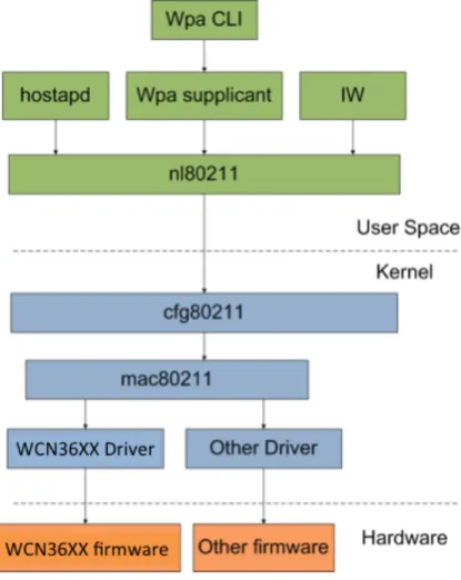
Figure 3.2 – Android OS architecture. ... 35
Figure 3.3 - Low level Android architecture ... 36
Figure 4.1 -‐ Line Topology with five routers. ... 46
Figure 4.2 – Discovery time and throughput vs. number of hops. ... 47
Figure 4.3 – Multi-Path Topology with four routers. ... 48
Figure 4.4 – Message diagram for detailing recovery time after a node failure. ... 48
Figure 4.5 – Line topology real testbed setup. ... 50
Figure 4.6 – Throughput for Open802.11s and B.A.T.M.A.N-advanced ... 51
Figure 4.7 – Open802.11s discovery time vs. number of hops. ... 52
Figure 4.8 – B.A.T.M.A.N-advanced bootstrap time vs. number of hops. ... 52
Figure 4.9 – Multi-path topology real testbed setup. ... 53
Figure 4.10 – Recovery time in case of node failure for B.A.T.M.A.N. and Open802.11s. ... 54
Figure 4.11 - Line topology with five routers ... 55
Figure 4.12 – Line Topology with four routers and one nexus 4. ... 55
Figure 4.14 - Throughput for Open802.11s and B.A.T.M.A.N-advanced ... 57
Figure 4.15 - Multi-path topology with three routers and one nexus 4 ... 57
Figure 4.16 - Multi-path topology with four routers ... 57
Figure 4.17 - Recovery time in case of node failure for routers and mobile phone. ... 58
Figure 4.18 - Multi-path topology with three routers and one nexus 4. ... 59
Figure 4.19 – New energy-aware metric path selection and metric values ... 60
Figure 4.20 – Metric value vs. remain energy ... 61
Figure 4.21 – Temperature vs. remain energy ... 62
Figure 4.22 – Voltage vs. remain energy ... 62
Figure 4.23 – Energy and voltage metric vs. time ... 63
Figure 4.24 – Voltage metric Value vs. remain energy ... 64
List of Tables
Table 2.1 - Comparison between mesh network projects with mobile devices ... 9
Table 2.2 - Comparison between mesh routing protocols ... 15
Table 2.3 - Comparison between mesh metrics ... 23
Table 2.4 - Comparison between energy-aware metrics ... 30
Table 3.1 – Comparison between possible devices to implement a mesh network. . 37
Table 6 - Values and definitions of each parameter from battery information API. .... 43
Table 7 - TP-Link TL-WDR4300 specifications ... 45
Table 8 - TP-Link TL-WR841N specifications ... 45
Table 9 – Nexus 4 specifications ... 45
List of Acronyms
AODV ARP B.A.T.M.A.N CMMBCR DSR DSVD EARM ECC ENT ETE ETT ETX HWMP iAWARE IEEE MAC MANET MCS MBCR mETX MMBCR MPR MREP MTPR OLSR OLSRd OMG OS OSI SINR SNR SPAN SQ TCAd hoc On-Demand Distance Vector Address Resolution Protocol
Better Approach To Mobile Ad-hoc Networks Conditional max-min battery capacity routing Dynamic Source Routing
Destination Sequenced Distance Vector Energy aware routing metric for IEE802.11s Elliptic Curve Cryptography
Effective number of transmission
Expected Transmission Energy route metric Expected transmission time
Expected transmission count Hybrid Wireless Mesh Protocol Interference Aware Routing Metric Institution of Electrical Engineers Medium Access Control
Mobile ad hoc networks
Modulation and Coding Scheme Minimum Battery Cost Routing
Modified expected transmission count Min-Max Battery Cost Routing
Multi Point Relay
Maximal residual energy path routing Minimum Total Power Routing
Optimized Link State Routing Protocol
Optimized Link State Routing Protocol daemon Originator Message
Operative System
Open Systems Interconnection
Signal to Interference and Noise Ratio Signal to Noise Ratio
Smart Phone Ad-Hoc Networks Sequence Number
TTL VPN WCETT WMN
Time To Live
Virtual Private Network Weighted cumulative ETT Wireless Mesh Network
1. Introduction
Mesh networks is today a technology with a very strong expansion. From everywhere arise useful usage scenarios for these type of networks such as riots, disasters and emergencies. In these scenarios, the lack of direct connectivity among mobile nodes and the network infrastructure occurs very often. In addition, the fact that, as far as we know, there is not an explicit standard for mesh networks incorporating handheld mobile devices that takes into account their specific limitations. This urges for novel research that studies the deployment of mobile devices in mesh networks.
It can be predictable that in such scenarios the existence of a technology that allows sending a text message or making a voice call through a mobile device becomes very useful and translates into a direct gain for the users.
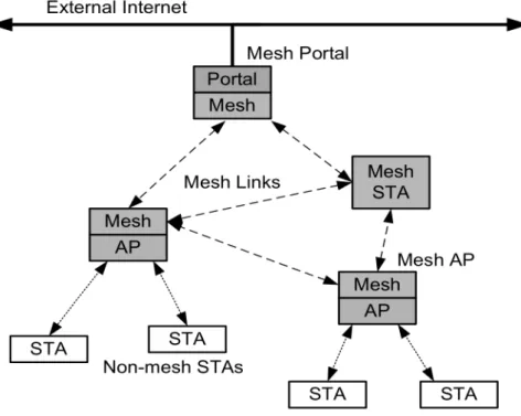
In short, the main motivation behind this study is to improve some relevant network characteristics such as reliability, coverage, interoperability, performance and capacity of mobile mesh networks without penalizing the battery autonomy of terminals. The final goal is to deploy a real mesh network that enables the mobile devices to communicate with each other without the support of any infrastructure. Wireless mesh networks (WMN) have emerged to address some limitations of traditional wireless networks. WMNs often consist of mesh clients and mesh routers. Normally, the mesh routers are static and power-enabled. The mesh routers also form a wireless backbone for the WMNs because these routers are directly connected directly to the wired network. Mesh clients are mobile and try to access the network directly via mesh routers or forming a multi-hop mesh topology with other mesh nodes. Therefore, based on these characteristics, the implementation of such networks satisfies the requirements of mobile devices. [1]
Figure 1.1 - Mesh network architecture
The research of mesh networks on mobile devices is a relatively new area and brings questions such as: the analysis of the best routing algorithms, routing metrics, optimizations in terms of battery autonomy, delay and the implementation of new functionalities not covered by the standard [2] .
The current contribution explores the concept of using mobile phones, which run the Android operating system, to create a mesh network. This type of implementation has different difficulties for implementing a traditional mesh network. Therefore, there are issues such as battery consumption, hardware limitations and the need to have root access to the mobile device.
Our work was initially based on a detailed study about the state of the art on mesh networks, more specifically in the topics of path selection and routing metrics. Throughout this research, it was possible to identify previous projects concerning mesh networks and mobile devices, as well as perceiving that any of these projects deployed mesh networks at Layer 2. This particular architectural aspect is very appealing because it ensures lower reaction delays to network failures than other upper layers implementations. We have also studied relevant routing protocols and mesh networks metrics. In this way, we have identified an open research issue. In fact, there was no available contribution in the literature, as far as we know, which used energy-aware metrics to control both the path selection and routing protocol
The outcome of current work aims to answer some still open research questions in the area of mesh networks with mobile devices, such as:
• Are the routing protocols and metrics defined in the current available standards suitable for the real implementation of a mesh network with mobile devices, or other proposals are necessary?
• Is it possible to implement a reliable and full-operational mesh network with mobile devices without compromising the delay and battery autonomy? Some recent proposed solutions enable the interconnection of devices in a mesh network configuration at Layer 2. These proposals explore new interconnection opportunities on mobile devices that were not possible until now, and launch new research challenges to be successfully addressed. Therefore, the main objective of the current work is the implementation of a mesh network using handheld mobile devices. Related to this main goal there are two other objectives, as follows:
• Optimize the battery power management of mobile devices within a mesh. • Limiting the delay in the mesh configuration, diminishing the setup and the
recovery time after a node failure.
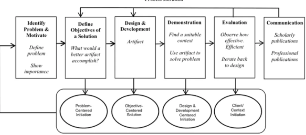
The current dissertation used the research method designated by the Design Science Research Methodology. This research method was fundamental to structure and plan all the necessary work to develop and evaluate a mesh network with mobile devices.
Figure 1.2 visualizes the methodology process we have used during the current work.
Based on the methodology shown in Figure 1.2 it is possible to detail further the main tasks that within each phase of that methodology we have performed, such as following described:
• Problem Identification: it is performed a problem analysis regarding to mesh networks implementations on mobile devices. That analysis was based on existing solutions and the problems that that cannot be solved.
• Define Objectives for a solution: this stage defined the work requirements, it also defined the evaluation criteria, which is based on a test scenario to evaluate the performance and viability of the mesh network.
• Design and Development: the process of design and development is to implement a mesh network with mobile devices. On each iteration will be evaluated the feasibility of the implemented features. As the implementation is based on the existing standard, it is necessary to make an incremental implementation of various specifications.
• Demonstration: the demonstration phase is based on functional and non- functional tests on the mesh network. On this phase, results will be generated using essentially a testbed.
• Evaluation: the mesh network proposal is subjected to the analysis and evaluation, based on the results collected on the demonstration phase. On this phase is verified if existing problems with the development should be corrected in the next iteration of development process.
• Communication: finally, the communication concerns in the writing of the dissertation and its final presentation and discussion. In additional, several scientific papers should disseminate the diverse results obtained from this work.
The major contributions of the current work, in the area of mesh networks, focus on enhancing the delay and the battery autonomy of mobile terminals without compromising the global mesh performance. In this context, we intend to study and compare the different solutions, including the standard one, for implementing a real mesh network on mobile devices. Additionally, we aim to study a new energy metric as an important criterion to discover the more convenient paths across the mesh infrastructure.
This current work has contributed to the research in the area of mesh networks with two publications: “Mesh Networks for Handheld Mobile devices”, a paper accepted and presented during the Conftele conference [3]; and a pending submited chapter [4] “Wireless Mesh Sensor Networks with mobile devices: a comprehensive review” for the Handbook of Research on Advanced Wireless Sensor Network Applications, Protocols, and Architectures.
The current document has the following structure:
§ Chapter 2 presents a review of the state of the art. It is divided in 5 sections. The first section is about projects that use mesh networks with mobile devices. Next, we discuss various solutions for protocol routing and path selection in mesh networks to understand if these solutions are compatible with the operation of mobile devices. The third section studies routing metrics for wireless mesh networks. Given the fact that a mobile device has to take into account the energy consumption, the next section introduces energy-aware routing metrics and the viability to work on mesh networks. The last topic discusses some relevant results obtained from two testbeds.
§ In Chapter 3 is described the solution and implementation for implementing a mesh network with mobile devices. It is also shown the necessary steps to reach the final formula for the two proposed metrics. This chapter is divided into 4 sections: mesh network protocol selection, mesh networks in mobile devices, new energy-aware metric for IEEE802.11s and integration of new metrics in mobile device.
§ Chapter 4 presents four testbeds scenarios. The first test was made with Open802.11s to verify if the network topologies and test procedures/configurations were appropriated. In a second test, two protocols were compared (Open802.11s and B.A.T.M.A.N-advanced) to decide which one is the more suitable for a WMN with mobile devices. Afterwards, it was build another test to verify if there is any kind of limitation of the mobile device when operating in a mesh network. Finally, the last real test was performed to study the new energy-aware metrics.
§ Chapter 5 concludes the current contribution and points outs some relevant future work in the related area of the current work.
2. Literature review
Mesh Networks have recently become an area of great interest in the field of research and have contributed to major advances in the area of wireless networks. This chapter analysis existing projects that use mesh networks with mobile devices in order to understand which of the layers of the OSI model are the more appropriate for implementing this type of network (Section 2.1).
In addition, existing routing protocols for mesh networks were analyzed to identify which ones can be more suitable to be deployed in mesh networks with mobile devices (Section 2.2). At a later stage, several metrics for mesh networks were analyzed to understand their characteristics and if they can be used to control how the routing paths are selected within the mesh infrastructure (Section 2.3). Because of the previous study, we have concluded that there are no metrics considering the battery status and, regarding that, it urges intensifying the research in the area of energy-aware routing metrics to increase the battery autonomy of mobile devices without penalizing too much the mesh performance (Section 2.4). Finally, a survey of the existing testbeds with mesh networks was made (Section 2.5).
2.1. Mesh networks implemented with
mobile devices
Mesh Networks on mobile devices have been the focus of various research projects and feature a wide variety of proposals and solutions for each specific case study. It is then necessary to analyze and compare current relevant solutions, finding out the most interesting features to be implemented, especially in mesh scenarios with handheld mobile devices.
The implementation of a mesh network in mobile devices can be done at different layers of the OSI model. The standard mesh solution [2] is implemented at Layer 2 (data link layer). There are also implementations at Layer 2.5 (with additional software between Layers 2 and 3), Layer 3 (Network) and Layer 7 (Application).
a. Open Garden
The Open Garden [5] is an existing implementation of mesh networks and mainly focuses on establishing a connection among devices in situations where there is no coverage or network capacity. It allows routing and multihop discovery so that users can share their own Wifi/3G/4G connection, which operates as a model of "crowd-source bandwidth". This solution uses the application layer to implement the mesh network.
The main advantage of Open Garden is to offer a mesh network without requiring a root access on the mobile device. This project generated the FireChat application [6] which has often been referred to in the media [7] due to its extensive use in recent protests.
However, Open Garden contains bugs in relation to VPN operation in the Android operating system [8] [9] [10] and has crashed on versions higher than 4.4.
b. Serval Project
The Serval Project [11] is a mobile ad-hoc network that allows mobile phones to communicate when cellular coverage fails and is designed to operate in diverse scenarios such as rural, remote and disaster. The main objective is to achieve a basic communication service to everyone, with a special focus in rural areas. This project uses both the network and application layers to implement a mesh solution. The Serval Project provides end-to-end privacy communication on voice calls and text messages using strong 256-bit Elliptic Curve Cryptography (ECC). This is one of the main advantages of the project, as it is a highly valued feature in communication systems. The ECC mechanism provides authentication and digital signature, data encryption and decryption, and identity management for the mesh network.
The roadmap of the project demonstrates that this is one of the most solid mesh networks for mobile devices. The team also developed specific hardware that can communicate with devices [12], achieving a broader coverage for the network.
c. SPAN Framework
The Smart Phone Ad-Hoc Networks (SPAN) [13] is an open source implementation of a generalized Mobile Ad-Hoc Network (MANET) framework. The main objective of the project is to provide a framework that is able to support any routing protocol that
works on a mesh network. This framework is injected into the existing Android network stack between OSI layers 2 and 3.
The SPAN project began as an internal investigation based on Wireless Tether for Root User, further developed by the MITRE Corporation and made available as open-source code on a GPLv3 license in December, 2011. SPAN is also based on the Serval project, with the main difference being the ability to use an arbitrary routing protocol. This is the opposite of what occurs in the Serval Project, which only uses the Better Approach To Mobile Ad-hoc Networks (B.A.T.M.A.N) routing protocol.
The possibility of multihop (shared with other projects) allows telephones with cellular access to perform a gateway role in the mesh network, providing Internet access to other devices. The most notable advantages offered by SPAN are the transparent functioning of the superior layers in relation to the network layer and the option to choose an arbitrary routing algorithm.
d. Commotion
Commotion [14] is an open-source project that uses wireless devices to create mesh networks. The project was developed by the Open Technology Institute in 2011 and launched in March 2013.
The main objective of Commotion is to provide an easy way to implement a mesh network for a wide audience through a specific software package. Commotion implements the mesh network at Layer 3.
The project is based on various open-source projects. Some of these projects are the Optimized Link State Routing Protocol daemon (OLSRd), which is used as the routing protocol for mesh network, OpenWRT, which is the operating system installed on routers and the Serval Project [11] that allows the use of security mechanisms for communication.
The project's main focus is to create a mesh network based on access points that can be extended to Android mobile devices. However, the main disadvantage is that it relies on a “Commotion infrastructure” for the terminals to communicate between each other.
e. Summary
Table 2.1 - Comparison between mesh network projects with mobile devices presents the more important characteristics that allow us to compare the mesh network projects with mobile devices discussed previously.
Table 2.1 - Comparison between mesh network projects with mobile devices Implementation Layer Multihop Standardize d Routing Protocol
Open Garden Application (7) Yes No Proprietary
Serval Project Network and
Application (3,7) Yes No BATMAN
SPAN Layer 2.5 Yes Yes Adaptable
Commotion Network (3) Yes No OLSRd
The currently study concludes that there is no project that uses Layer 2 to implement the mesh network. So, none of the projects mentioned above follows the recommendations and specifications of IEEE 802.11s [1]. A very important reason for choosing Layer 2 to implement the mesh network on mobile devices is to have more information available from the physical and MAC layers, which can be used by the routing algorithm. Additionally, operating at Layer 2 has strong benefits, by reducing the time delay to react to unexpected problems and to converge to a new operational configuration, as compared with implementations at higher layers.
In terms of routing protocols, each project chooses a different protocol. Nevertheless, the SPAN allows the usage of more than one routing protocol without any significant changes in the network configuration
2.2. Path selection and routing protocols
The routing protocols for mesh networks can be classified into three main categories: reactive (on-demand), proactive and hybrid. For the on-demand routing protocols, the path between a sender node and a receiver node is created only after the former transmitted a packet to the latter node. Conversely, in proactive protocols, each node maintains path information to all other nodes on its routing table before any transmission. Finally, the hybrid solution can support both categories described above. In the following text, is discussed several routing protocols for WMNs.
a. AODV
Ad-hoc On-Demand Distance Vector (AODV) [15] is a reactive-routing protocol for WMN. As its name indicates the algorithm is based on a distance vector protocol. The path discovery is done by sending a message route request (RREQ) to the neighbors with the destination address and the sequence number. The use of a destination sequence number is a mechanism to avoid loops, similar to other algorithms based on distance vector. The nodes that receive the message increment the sequence number and update their routing table.
When the destination node receives the request message, it responds with a route reply (RREP) message back to the requesting node. When an intermediate node does not know the route that intermediate node sends a route error (RERR) message to the source node and the path discovery process is repeated.
b. HWMP
The Hybrid Wireless Mesh Protocol (HWMP) is defined in IEEE 802.11s [2] as the default routing protocol at the MAC layer. The HWMP protocol is based on Ad-hoc On Demand Distance Vector (AODV) and can be categorized as a hybrid solution because it supports the following modes: reactive (on-demand mode) and proactive. On-Demand Mode
In On-Demand mode, a Path Request (PREQ) message is broadcasted by a Mesh STA (source) with information about the MAC address of destination Mesh STA. All PREQ messages contain a unique sequence number that is used to know the freshness of the PREQ on receiver. When an intermediate Mesh STA receives a PREQ, it creates or updates the path to the source only if the sequence number is higher than the previous know one or it has the same value but with a better metric. If the intermediary Mesh STA does not have the path to the destination, then the received PREQ message is forwarded to the next node until the destination Mesh STA is reached. When this destination node receives the PREQ, it sends a unicast Path Reply (PREP) message to the source Mesh STA.
Figure 2.1 - HWMP on-demand route discovery Proactive Mode
In the proactive mode, one of the nodes is selected as the root node. This node periodically sends PREQ messages. These PREQ messages are sent in broadcast to the neighbors. Each node after receiving a PREQ message sends a PREP back to the root. Alternatively, any node can send to the root a Route Announcement (RANN) message that enables the former node to build on-demand a path to the root node. Thus, the root gets a routing table fulfilled with all the possible paths traversing the mesh, forming a tree-based network topology.
c. B.A.T.M.A.N
The B.A.T.M.A.N. [16] is a proactive routing protocol for WMN. The operating principle is to spread the knowledge about the best destination paths among all nodes. Each node receives and maintains only the information about the next hop towards remainder destination. Another important feature is the flooding mechanism based on events that prevents the occurrence of contradictory messages about the network topology (usually the reason for the existence of loops) and limits the number of messages in the network.
Each node n broadcasts an originator message (OMG) to inform the neighboring nodes of its existence. OMG messages are small packets that contain information about the original address, the address of the node that transmits the packet, Time to Live (TTL) and sequence number (SQ). Neighbors resend the message to its neighbors to inform the existence of the node n. Each node can make a re-broadcast of an OMG only once, and only if it is received by the node that is currently the best next hop to the creator of the OMG.
Currently the algorithm exists in two different versions: Batmand (Batman daemon) and Batman-advanced (Barman-adv). The difference between the two versions is how they are implemented, although the main operation is the same. The Batmand is implemented at layer 3 of the OSI model while Batman-adv works at layer 2.
The main differences are related to the implementation in distinct layers. The Batman-adv only needs MAC addresses to work while Batmand requires IP addresses. Batman-adv emulates an Ethernet bridge, causing all nodes appear to be connected by a direct link; so the above layer protocols are unaware of the multihop network topology.
d. DSDV
Destination Sequenced Distance Vector (DSDV) [17] is a proactive routing protocol for WMN based on Bellman-Ford algorithm.
In this protocol all the nodes keep in their routing table the next hop record and the number of hops required to reach the possible destinations from this node, where each entry is associated with a sequence number.
The updates are transmitted periodically or immediately when significant topology changes are detected. The update can be done in two ways: in “full dump” the node
transmits the complete routing table or “incremental update”, where the node sends only the new entries.
When a node receives an update message (full dump or incremental) it compares the information to that saved in the routing table and considers the entry with the most recent sequence number as the next to be used in the current routing decision. If the sequence number is equal then it considered the entry with the best routing metric.
Due to its architecture and operation, DSDV is suitable for networks with few devices, as they require regular incremental updates to their routing tables. This feature cause certain limitations related to battery consumption, which is a major drawback in networks with limited resources in terms of energy.
e. OLSR
The Optimized Link Sate Routing (OLSR) [18] is a proactive routing protocol for WMN based on classic link state routing.
The basic operation of OLSR is the same as the classic link-state routing, although with some additional features. One of the differences from the classic version is the use of MultiPoint Relays (MPR) to forward the packets through the network. This feature reduces the number of transmissions required to create the network topology and the number of control messages to keep the network operating in a correct state. This protocol has two types of control messages: neighborhood and topology messages, called respectively Hello messages and Topology Control (TC) messages. The Hello message has the function of neighbor discovery and TC messages are used for topology dissemination.
The OLSR protocol is especially useful for large and dense networks because the MRP’s technique works well in these scenarios.
f. BABEL
BABEL [19] is another proactive routing protocol for mesh networks that follows the distance-vector routing principles. It is based on DSDV [17] and the main difference to the classical distance-vector protocols is that is loop-free. This problem is avoided by using feasibility conditions and sequence numbers.
For selecting the more suitable route the BABEL protocol uses historical information about link quality to prevent a node changing several times the routes to the destinations, limiting the network instability.
In order to discover paths, each node periodically sends hello messages to its neighbors with a sequence number. Furthermore, "I heard you" messages (IHU) are also sent as replies to neighbors that previously sent hello messages. So based on these two messages is calculated the cost of each link connection.
The BABEL protocol has limitations for stable and large networks because their operation is based on constant updates of routing tables, which causes a high amount of traffic. This operation may cause a huge energy consumption for devices and for this reason this protocol is not adequate for networks with mobile devices.
g. DSR
Dynamic Source Routing (DSR) [20] is a reactive protocol conceptualized for mesh multi-hop wireless and uses IP source routing. The main characteristic of DSR is that each node stores the complete path to destination instead of the next hop (unlike AODV).
As such, all the DSR messages contain the list of all necessary nodes to reach the destination. This protocol allows the network to be self-organized and self-configured without an infrastructure.
h. Summary
Table 2.2 summarize the main characteristics of the discussed mesh routing protocols.
Table 2.2 - Comparison between mesh routing protocols Type Routing Metric Energy Efficient Mobility Load Balancing Reliability
HWMP Hybrid Airtime No Yes No Yes
BATMAN Proactive Transmission Quality (TQ) No Yes Yes Yes
AODV Reactive
Hop, ETX, ETT or iAWARE
No Yes No Yes
OLSR Proactive Hop, ETX or ETT No Yes No Yes
DSDV Proactive Hop No Yes No Yes
BABEL Proactive Hop, ETX No Yes No Yes
DSR Reactive Hop No Yes Yes Yes
Regarding the protocol types, the HWMP is the only that can operate in either proactive or reactive mode. The B.A.T.M.A.N, OLSR, DSDV and BABEL are proactive routing protocols. The reactive algorithms are AODV and DSR.
All analyzed protocols implement mobility and reliability features. The load balancing feature is only supported by DSR and B.A.T.M.A.N.
It can be seen that none of the analyzed protocols consider the energy consumption. This is one of the main critical issues and concerns in in networks with limited resources in terms of energy and routing protocols for mesh should be aware of it. We will discuss this novel aspect in section 2.4.
2.3. Metrics for mesh networks
The study of routing protocols has been a very active area of research in mesh networks. In this sphere, the type of metric used is important in controlling the network operation. The routing metrics have diverse goals such as to optimize performance, maximize battery lifetime, increase throughput and minimize latency.
a. Hop Count
In Ad hoc networks, the hop count routing metric is very common due to its very simple implementation.
The hop count is the simplest metric routing because it is evaluated as the number of necessary hops to reach the destination. For this reason, the hop count is by default used by many major routing protocols such as AODV, DSR, DSDV and OLSR. The main advantages of this metric are not only its deployment simplicity but also its stability, especially for networks with mobility, where it reduces the number of changes applied to the network when compared with other metrics.
On the other hand, the fact that all links are managed in the same way is a disadvantage, as parameters such as link capacity, diversity mechanisms, link load and interference are not taken into account, which may result in path choices being made with high delays and low throughput. Consequently, the use of hop count may result in degraded network performance.
b. Airtime Metric
The airtime [21] is the default routing metric for mesh networks specified in the IEEE 802.11s standard [2]. Airtime analyzes information related to the utilization of the channel during a transmission, for example, overhead, transmission time and frame error rate. It represents the amount of channel resource consumed by transmitting a frame over a particular link.
The Airtime metric is given by following expression:
𝐶
!= 𝑂
!"+ 𝑂
!+
𝐵
!𝑟
𝑥
1
1 − 𝑒
!" ( 1 )where Oca ,Op and Bt are constants that representing, respectively, channel access
overhead, protocol overhead and the number of bits in the test frame. The term r is the data rate in Mbps and ept is the frame error rate. The way of measuring ept is not
specified in 802.11s [2].
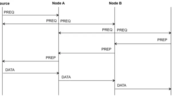
Figure 2.3 – PREP and PREQ exchanged messages to calculate de Airtime Link metric cost [22]. In the first step node s broadcasts a PREQ message, next a and b re-broadcasts the PREQ with the metric value updated towards s. The next phase (response), t sends a PREP in response to PREQs. Finally, a or/and b updating the metric and forward the PREP towards t.
The airtime does not define any load balancing mechanism that can lead to network paths through congested links. Ignorance of the existence of intra-flow interference can also have a negative impact on the network performance. For these reasons, analyzing the trend of airtime metric, one can not predict the current state and quality of a network link. [23]
c. Transmission Quality (TQ)
The TQ [24] is the routing metric used by B.A.T.M.A.N. and represents the quality of the path for a specific originated message. TQ as the name suggests, represents only the capability of sending data and not receiving. The local transmission quality value can not be directly calculated, because the source node does not have sufficient information. For this reason Receive Quality (RQ) and Echo Quality (EQ) need to be calculated.
The local Transmission Quality is given by in (2).
𝑇𝑄 =
𝐸𝑄
𝑅𝑄
( 2 )The RQ value is calculated as the fraction of the received OGMs from a node and the number of expected ones. The EQ value is computed as the fraction of locally generated OGMs and the number of times that it receives the rebroadcasted OGM back from a neighbor.
The Path TQ represents the total transmission quality for an entire path. When a node generates a OGM, the TQ value is set to 255 and after is broadcasted. The value is updated by neighbors with the local TQ value and rebroadcasted, until reach the destination node. Therefore, the total TQ is expressed in expression (3).
𝑃𝑎𝑡ℎ𝑇𝑄 = 𝑃𝑎𝑡ℎ𝑇𝑄 × 𝐿𝑜𝑐𝑎𝑙𝑇𝑄
( 3 )To assure that only the best bidirectional links are chosen, the TQ metric assigns a penalty to links that communicates in one direction but not via the other. Therefore if the RQ value is poor the path TQ will be affected significantly. Thus, its expression is given in (4).
𝑃𝑎𝑡ℎ𝑇𝑄 = 𝑃𝑎𝑡ℎ𝑇𝑄 × (1 − 1 − 𝑅𝑄
!)
( 4 )Another penalty is relative to the number of hops. This penalty is assigned in relation to a fixed value (TQ_HOP_PENALTY) every time that a OGM is rebroadcasted. The Hop penalty is applied according to equation (5).
𝑃𝑎𝑡ℎ𝑇𝑄 = 𝑃𝑎𝑡ℎ𝑇𝑄 × (1 − 𝑇𝑄_𝐻𝑂𝑃_𝑃𝐸𝑁𝐴𝐿𝑇𝑌)
( 5 )These penalties are very important to save bandwidth, reduce delay and avoid the reduction of throughput caused by self-inference.
d. Expected Transmission Count (ETX)
The ETX [25], as its name indicates, is defined by the number of transmissions required to transmit a packet successfully through a wireless link. The total number of the transmissions associated to a network path is the sum of transmission through all the individual links of that path.
To calculate the metric ETX associated to an individual link, each node periodically sends a fixed number of N probe frames in broadcast over a fixed time period T. Upon receiving the messages, the nodes calculate the forward delivery ratio dfwd (probability that the packet was successfully received at the source node) by the expression (6).
𝑑
!"#=
𝑅
!𝑁
( 6 )Where Rf is the number of received frames from the previous sent N frames in the
forward direction. When the nodes receive a probe frame, they count the probe frames received via piggyback in message dfwd in order to compute the reverse
delivery ration drvs (probability that acknowledgment of the packet was successfully
received at the source node).The ETX metric can be evaluated as shown in (7)
𝐸𝑇𝑋 =
1
𝑑
!"#× 𝑑
!"# ( 7 )The main advantages of ETX are following explained. It considers packet loss ratios in its computation. It is an isotonic function that guarantees an efficient computation of paths with a low computing cost. It ensures a loop-free final result. However, the ETX does not consider interference or the characteristic that links may have different transmission rates. The ETX is not suitable for networks with high mobility because it takes some time to compute the necessary values (dfwd and drvs).
e. Modified Expected Transmission Count (mETX) and Effective
Number of Transmission (ENT)
In order to overcome some disadvantages of ETX, mETX and ENT have been both developed with certain changes on the link variance of the transmission to make the ETX more robust and to consider the routing quality. [26]
Modified ETX is evaluated in (8).
𝑚𝐸𝑇𝑋 = 𝑒𝑥𝑝 𝜇 +
1
2
𝜎
! ( 8 )Where
𝜇
represents mean packet loss ratio and𝜎
! is the variance of packet loss ratio. The main difference between mETX and ETX is that mETX considers probe losses. Based on the corrupted bit position in the probe message, the mETX metric computes bit error probability.𝐸𝑁𝑇 = 𝑒𝑥𝑝 𝜇 +
1
2
𝛿𝜎
! ( 9 )Where 𝛿 is the strictness of the loss rate requirement. ENT is very similar to mETX, with the difference of the parameter 𝛿, that allows an additional degree of freedom. Both, mETX and ENT are ETX improvements, although they still fail to address intra-flow (nodes on the same path or intra-flow on the same channel competing between each other for channel bandwidth) and inter-flow (caused by other flows that are operating on the same channel) interference problems in network.
f. Expected Transmission Time (ETT)
The ETT [27] is an improvement over the ETX routing metric described above. In order to overcome the main disadvantage of this metric a parameter was added that considers the link transmission rates.
Thus, ETT can be expressed as show in (10).
𝐸𝑇𝑇 = 𝐸𝑇𝑋 ×
𝑠
𝑏
! ( 10 )Where s is the packet size and bt is the transmission rate of each individual link.
Therefore, with these additional parameters is possible to take into account the average time of a link transfer regardless of whether or not the transmission is successful.
However, the ETT still has the disadvantage of not fully analyzing the intra-flow and inter-flow interference in the network. This drawback makes it possible for this routing metric to choose a route that uses only one channel instead of other alternative routes with higher channel diversity.
g. Weighted Cumulative ETT (WCETT)
The WCETT [27] is an improvement over the ETT, also considering intra-flow interference.
𝑊𝐶𝐸𝑇𝑇 = 1 − 𝛽 ×
𝐸𝑇𝑇
!!
!!!
+ 𝛽 × max
! !!!!
𝑋
! ( 11 )Where n represents the total number of nodes, k specifies the total number of different channels used in path, 𝛽 is a tunable parameter with values between 0 and 1, Xj is the sum of transmission times required for all hops on channel j and is
defined as shown in (12).
𝑋
!=
𝐸𝑇𝑇
!! !"#" !!!""#$$ !
1 ≤ 𝑗 ≤ 𝑘
( 12 )From (11), the first parameter is the sum of each ETT link and favors the shorter and high quality paths. The second parameter is the sum of ETT for all links of a particular channel, choosing that which has a higher value. The result is, therefore, a higher value for paths with a large number of links operating on the same channel, which hence favors channels with high diversity and low intra-flow interference. However, there are still several problems with this metric. In fact, the WCETT metric only considers the number of links that operate on the same channel and its ETTs, but it does not take into account the location of these links. WCETT is not isotonic (not ensure that the order of the weights of two paths are preserved if they are appended or prefixed by a common third path), what makes it difficult to use in efficient algorithms to find minimal weight paths, such as Bellman-Ford or Dijkstra’s algorithm.
h. Interference Aware Routing Metric (iAWARE)
The iAWARE [28] appears as the first routing metric that takes into account intra-flow and inter-flow interference. The iAWARE uses ETT and values of Signal to Noise Ratio (SNR) and Signal to Interference and Noise Ratio (SINR) in order to obtain information about interference with its neighbors.
The iAWARE metric is expressed by the equation shown in (13).
𝑖𝐴𝑊𝐴𝑅𝐸 = 1 − 𝛼 ×
𝑖𝐴𝑊𝐴𝑅𝐸
!!
!!!
+ 𝛼 × max
where Xj is the inter-flow interference in the network, k is the total number of channels, n is the total number of links,
𝛼
represents the trade-off parameter between intra-flow and inter-flow interferences in path.The term iAWAREi is detailed in (14).
𝑖𝐴𝑊𝐴𝑅𝐸
!=
𝐸𝑇𝑇
!𝐼𝑅
! ( 14 )where IRi is the interference ratio of the link I and is given by the equation shown in (15).
𝐼𝑅
!=
𝑆𝐼𝑁𝑅
!𝑆𝑁𝑅
! ( 15 )The term and Xj is expressed in (16).
𝑋
!=
𝐸𝑇𝑇
!! !"#" !!!""#$$ !
1 ≤ 𝑗 ≤ 𝑘
( 16 )The iAWARE metric is not isotonic and cannot be used in a link state routing protocol. The interference is only calculated on the receiver side and this parameter is ignored on the sender side. This routing metric also captures the effects of variation in link loss-ratio as well as the differences in transmission rate.
The iAWARE uses the value of the ETT and IR to evaluate the metric. If the IR value is higher than the value of ETT, the term iAWAREi will have a lower value and consequently the metric will choose a path with a lower ETT but higher interference. So, the main disadvantage is that it gives a greater weight to the ETT compared to the interference link.
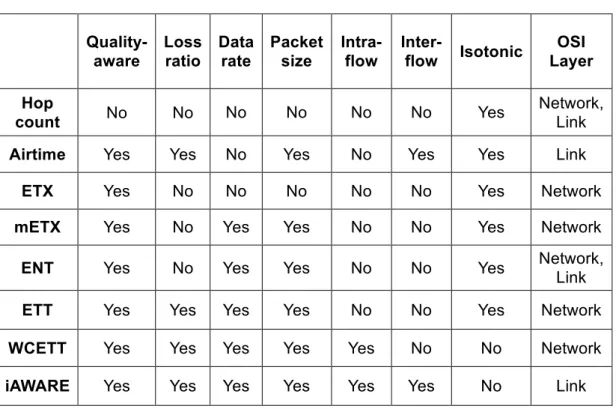
i. Summary
Table 2.3 - Comparison between mesh metrics
Quality-aware Loss ratio Data rate Packet size Intra-flow Inter-flow Isotonic OSI Layer Hop count No No No No No No Yes Network, Link
Airtime Yes Yes No Yes No Yes Yes Link
ETX Yes No No No No No Yes Network
mETX Yes No Yes Yes No No Yes Network
ENT Yes No Yes Yes No No Yes Network, Link
ETT Yes Yes Yes Yes No No Yes Network
WCETT Yes Yes Yes Yes Yes No No Network
iAWARE Yes Yes Yes Yes Yes Yes No Link
The metric types listed in Table 2.3 can be divided into two categories: Topology Based and Active Probing Based. In Topology Based category is inserted the Hop Count metric that is based exclusively on the network topology to make decisions. All the others are Active Probing Based and perform active measurements and use probe packets to estimate the metric values.
The main objective of the metrics in Table 3 are to minimize the delay and to maximize the probability of data delivery. The only metric that allows the detection of intra-flow and inter-flow interference is iAWARE, however this metric not have an isotonic behavior.
After analyzng the existing metrics TQ (B.A.T.M.A.N.) and Airtime (standard IEEE802.11s), it turns out that none of the used metrics take into account the power consumption, making it a major drawback to use in sensor networks. In the next section is presented proposals for metrics that already take into account the energy consumption, but so far have not been sufficiently studied in mesh networks with mobile devices.
2.4. Energy-aware routing metrics
Energy consumption can be an important constraint in a network with mobile devices and therefore it is crucial that the routing protocol should use a metric that has this aspect into account. Energy-aware routing metrics can be managed at a single layer or using a cross-layered design. In that sense the parameters used in the metric can be obtained from some layers such as: Physical Layer (transmission power control), Data Link Layer (MAC protocol operation) and Network Layer (routing algorithm). The main objectives of such metrics are: minimization of overall energy consumption to maximize the time until a node turn off due to lack of battery.
a. Minimum Total Power Routing (MTPR)
The MTPR [29] was one of the first proposed metrics that consider the power consumption. The main objective of this metric is selecting the path with the minimum total transmission power. Therefore the metric calculates the total energy consumed over the route and makes a decision based on that value.
If we assume a route 𝑟!= 𝑛!, 𝑛!, … , 𝑛! where 𝑛! is the source node and 𝑛! is the
destination node, the MTPR metric is expressed by the following equation:
𝑃(𝑟
!) =
𝑇
!!!
!!!
𝑛
!, 𝑛
!!! ( 17 )𝑇 𝑛!, 𝑛! represents the energy consumed for a transmission over the hop 𝑛!, 𝑛! . A disadvantage of this metric is that it does not take into account the battery of the nodes. It is expected that nodes that need to forward a lot of traffic have a shorter battery lifetime and do not contribute to a reliable network operation.
b. Minimum Battery Cost Routing (MBCR)
In order to account the battery capacity for all nodes over the network, MBCR [30] is based in the sum of the remaining battery capacity for the all intermediate nodes. Assuming that all nodes have the same battery capacity in full mode, the battery cost function for node 𝑛! is given by the equation shown in (18).
𝑓
!(𝐸
!) =
1
𝐸
! ( 18 )where Ei is the residual battery capacity.
The total battery cost Rj among the complete path p, with D nodes is expressed by the equation (19).
𝑅
!=
𝑓
!(𝐸
!)
!!∈!
( 19 )
Finally, to discover the route that minimizes the total cost among the nodes, we select a route p’ with the minimum battery cost, as shown in (20).
𝑝′ = 𝑚𝑖𝑛 𝑅
!| 𝑗 ∈ 𝑃
( 20 )Where P is the full set of possible paths.
If all nodes have the same battery cost then MBCR selects the sorter hop path. The main disadvantage of this metric is the fact that uses only the total path value of battery cost. In cases when the route selected have a large discrepancy between nodes, for example nodes with full-charged battery and others with a low level of battery energy, this can be a strong drawback because some nodes may be turned off.
In [31] the authors propose an improvement to MBCR, resulting in a battery capacity defined as a cost function considering the number of hops. This change is expressed in equation (18).
𝑅
!=
1
𝐻
𝑓
!(𝐸
!)
!!∈!
( 21 )
Where H is the number of hops for the path.
This main aim of this solution is reduce the total transmission power consumption and balance the energy consumption among all nodes. Although, it does not yet consider the individual cost of nodes.
c. Min-Max Battery Cost Routing (MMBCR)
MMCBR [30] is an improvement to the original MCBR to manage the nodes more fairly. MMCBR avoid nodes with very low remaining battery and ones with large battery capacity are favored to be elected to establish routes.
The objective of this metric is for each route, select the battery cost with the maximum value among all nodes. Hereupon we can change the Equation (18) to consider that as shown in (22).
𝑅
!= 𝑚𝑎𝑥
!∈!𝑓
!(𝐸
!)
( 22 )Then, the route is selected accordingly to (23).
𝑝′ = 𝑚𝑖𝑛 𝑅
!| 𝑗 ∈ 𝑃
( 23 )With MMCBR there is no guarantee of minimum total transmission power in all cases. This creates a tradeoff between the priority to an individual node and the overall system energy optimization.
d. Conditional Max-Min Battery Capacity Routing (CMMBCR)
CMMBCR [32] is a combination of two previously described protocols into on a single hybrid metric, MTPR and MMBCR. In the above metrics was considered a cost function but in this metric is used the battery capacity. A threshold parameter γ is used to define the minimum remaining percentage of battery capacity for each node that ranges between 0 and 100.
For each node j CMMBCR finds the minimum capacity R! for all nodes in the route.
Finally, the R! and γ value is compared. If R! ≥ γ then MTPR is applied, else the
route is selected using MMBCR.
With this hybrid metric the objectives of maximize the lifetime of each node and use the battery fairly are both contemplated.
e. Maximal Residual Energy Path Routing (MREP)
MREP [33] is a metric proposed by Chang and Tassiulas based on the remaining battery capacity and the necessary transmission energy. The cost of a node is inversely proportional to the remaining battery capacity. The main objective of this
metric is to balance the energy consumption in all paths, through the choice of the path with maximum residual energy.
Considering E! the residual energy at node j and e!,! the energy cost to send a packet
from node i to node j, the authors proposed two metrics.
The reciprocal of the residual energy d!,! for a node is expressed by equation (24).
d
!,!=
1
E
!− e
!,! ( 24 )MREP using the lexicographical ordering, and compare two paths by the examination of the highest cost node on each path. The path with highest cost node has the lowest cost in lexicographical ordering..
Other proposals for a simpler implementation were presented by Jae-Hwan Chang and Tassiulas. The first modification stores and uses the largest element of the path for comparison and is given by (25).
D
!(!!!)= min min max d
!,!, D
!(!), D
!(!) ( 25 )where D!(!) is the distance of the path from node i to the destination at step n. Other solution uses the Bellman-Ford equation as shown in (26).
D
!(!!!)= min min d
!,!+ D
!(!), D
!(!) ( 26 )The fourth proposal is based on the number of packets that can be delivered with the remaining energy of the nodes. This can be expressed as shown in (27).
d
!,!=
e
!,!E
! ( 27 )In [34] another expression to calculate the metric is presented as it is visualized in (28).
d
!,!=
e
!,!!!E
!!!
where R! is the residual energy at node i and x!, x! and x!represent weighting
non-negative values .
A disadvantage of this metric is the difficulty of determine the remaing energy on each node. This metric aims to maintain the fairness of the entire network and always trying to use the paths where there is a maximum value of residual energy, however does not take into account the power consumption.
f. Expected Transmission Energy Route Metric (ETE)
ETE [35] is a metric for WMSNs with the aim of improving the Airtime Link metric to take into account the energy consumption. This metric tries to ensure that all nodes have an identical energy consumption and simultaneously keeping the average power consumption at low values. To make this possible ETE introduce a threshold mechanism. When the energy of a node is below the threshold, this one does not join the metric calculation and does not forward packets.
The ETE metric is expressed by the equation (29).
𝑐′
!= 𝑂
!"+ 𝑂
!+
𝐵
!𝑟
+
𝐸
!"!#100𝐸
! !! !!!1
1 − 𝑒
!"+
𝐸
!"𝐸
!"!# !! !!!𝑛
! ( 29 )where E! is the remaining energy of node i after the transmission, E!" is the energy consumption of node i and n! is the number of nodes along the selected path. O!",
O!, B!, r and e!" are constants defined for Airtime Link Metric and described above.
The tests carried out by simulation show that the ETE has better performance in prolonging the lifetime of the network and maximize the throughput when compared with Hop Count and Airtime Metric.
g. Energy Aware Routing Metric for IEE802.11s (EARM)
In order to address the lack of metrics for standard 802.11s mesh networks, has been proposed a new metric to replace the Airtime Link [36].
This proposal takes into account the residual energy of a node by calculating the total energy consumed by a node based on its state. The metric defines five states, IDLE: the node is idle; CCA_BUSY: at this stage the node is busy; TX: the node is transmitting packets; RX: the node is receiving packets and SWITCHING: the node is switching from a channel to another one.
![Figure 2.3 – PREP and PREQ exchanged messages to calculate de Airtime Link metric cost [22]](https://thumb-eu.123doks.com/thumbv2/123dok_br/19180514.945094/31.892.138.757.106.290/figure-prep-preq-exchanged-messages-calculate-airtime-metric.webp)


![Figure 3.2 – Android OS architecture. [42]](https://thumb-eu.123doks.com/thumbv2/123dok_br/19180514.945094/49.892.149.749.191.754/figure-android-os-architecture.webp)