VisualLISA: A Visual Environment to Develop
Attribute Grammars
Nuno Oliveira1
, Maria Jo ˜ao Varanda Pereira2
, Pedro Rangel Henriques1
,
Daniela da Cruz1
, and Bastian Cramer3
1
University of Minho - Department of Computer Science, Campus de Gualtar, 4715-057, Braga, Portugal {nunooliveira,prh,danieladacruz}@di.uminho.pt
2
Polytechnic Institute of Braganc¸a
Campus de Sta. Apol ´onia, Apartado 134 - 5301-857, Braganc¸a, Portugal [email protected]
3
University of Paderborn - Department of Informatics F ¨urstenallee 11, 33102, Paderborn, Germany
Abstract. The focus of this paper is on crafting a new visual language for attribute grammars (AGs), and on the development of the associated pro-gramming environment. We present a solution for rapid development of VisualLISAeditor usingDEViL.DEViLuses traditional attribute gram-mars, to specify the language’s syntax and semantics, extended by vi-sual representations to be associated with grammar symbols. From these specifications a visual programming environment is automatically gener-ated. In our case, the environment allows us to edit a visual description of anAGthat is automatically translated into textual notations, including anXML-based representation for attribute grammars (XAGra), and is in-tended to be helpful for beginners and rapid development of smallAGs. XAGraallows us to useVisualLISAwith other compiler-compiler tools. Keywords:Attribute Grammar, Visual Languages, XML Dialect, DEViL, VisualLISA, XAGra.
1.
Introduction
AnAGcan be formally defined as the following tuple:AG= (G, A, R, C), where
G is a context-free grammar, A is the set of attributes, R is the set of
eval-uation rules, and C is the set of contextual conditions. Each attribute has a
type, and represents a specific property of a symbol X; we write X.a to
in-dicate that attribute ais an element of the set of attributes of X, denoted by
A(X). For eachX (terminal or non-terminal),A(X)is divided into two disjoint
sets: theinherited and thesynthesizedattributes. EachRis a set of formulas,
like X.a = f unc(..., Y.b, ...), that define how to compute, in the precise
con-text of a production, the value of each attribute. EachCis a set of predicates,
pred(..., X.a, ...), describing the requirements that must be satisfied in the
As can be deduced from this complex definition ofAGs they are not as easy to specify as people would desire because there is a gap between the problem solution (the desired output) and the source language that must be interpreted. The user must take care on choosing the appropriate attributes and their eval-uation rules. Since the beginning, the literature related with compilers presents
AGs using syntax trees decorated with attributes. So it is usual to sketch up
on paper trees with attributes representing anAG. This strategy allows the
de-velopers to imagine a global solution of the problem (in a higher abstraction level) and to detect complex dependencies between attributes, symbols and functions, avoiding spending time with syntax details. However, such informal drawings require the designer to translate them manually into the input notation of a compiler generator. The person who drew it must go through the translation of the pencil strokes into the concrete syntax of the compiler generator. These
inconveniences make the developers avoid the usage of AGs and go through
non systematic ways to implement the languages and supporting tools. So, in
this paper, we develop a Visual Language (VL), as a meta-language to write
AGs, based on a previous conceptualization that we have proposed in [1]. The
idea of thisVLis not only about having a nice visual depiction and then to
trans-late it into a target notation, but also about syntactic and semantic consistency checks.
VLs and consequently the Visual Programming Languages (VPLs) aim at
offering the possibility to solve complex problems by describing their properties or their behavior through graphical/iconic definitions [2]. Icons are used to be composed in a space with two or more dimensions, defining sentences that are formally accepted by parsers, where shape, color and relative position of the icons are relevant issues. A visual programming language implies the existence
of aVisual Programming Environment(VPE) [3, 4], because its absence makes
the language useless. Commonly, a visual programming environment consists of an editor, enriched by several tools to analyze, to process and to transform the drawings.
The main idea of this work is the development of aVPE, namedVisualLISA,
that assures the possibility of specifying AGs visually, and to translate them
into plain text specifications or, alternatively, into a universal XML
representa-tion designed to support genericAGspecifications. The original objective of this
environment is to be used as front-end forLISA[5] system, diminishing the
dif-ficulties regarding the specification ofAGs inLISA. However, the generality of
the environment enables its use with systems other thanLISA.
The visual programming environment is automatically generated byDEViL,
our choice among many other tools studied; so, in this paper, the system is introduced and its use explained. However, our objective in this paper is not concerned with the discussion of compiler development tools, but show the be-fits of using an effective one.
In section 2, related work is presented. In Section 3 and 4,VisualLISA
scheme for bothLISA(the first target), andXAGranotations. In Section 6, the
DEViL generator framework, used for the automatic generation of the visual
editor, will be presented. In Section 7, following the informal conception and its
formalization, usingDEViL, the visual language and the editor implementation
is shown. An overview on how to use the editor to describe anAG, is given in
Section 8.
In Section 9,XAGradialect is formally presented. Its main idea is to
gen-eralize the output of AG editing tools; instead of generating a description for
a specific compiler generator, the editor under development can produce this
general purpose dialect. Then to use this editor as aFront End (FE) for a
spe-cific generator, it is only necessary to resort to a simple translator to convert the
XMLdescription into the specific notation of thatCG. This approach raises the
usefulness of the editor, as it can be used as aFEfor a larger range of
grammar-based generators. However, as its applicability does not end here, we introduce,
in Appendix A,XAGraAl, a tool that, based onXAGraspecifications, performs
grammar analysis and transformations. The paper is concluded in Section 10.
2.
Related Work
Despite of existing many other applications for AGs, they are commonly
as-sociated with the development of computer languages and related tools like parsers, translators, compilers, and others. In this context, the language engi-neers, started to develop tools to systematize and automatize the process of
definingAGs. So, several works on this area may be cited.
LISA[5, 6] is a compiler generator based on attribute grammars, developed
at University of Maribor at Slovenia. Its main objective is to generate a compiler for a language. The compiler is created by the specification of a textual attribute grammar. It automatically generates graphical and visualization tools [7] to
in-spect the written grammar, but it always need a textual specification of theAG.
In the same way, AnTLR [8], a powerful compiler generator, requires textual
specifications for the language grammar. This system providesonline
visualiza-tion of the grammar producvisualiza-tions but it does not provide any visualizavisualiza-tion about the attributes neither the semantic rules of each production.
Other similar compiler generators like UltraGram [9] or ProGrammar [10] also produce graphical tools to ease the understanding of the grammar. But still, the input for these compiler generators is always a text-based specification.
The same happens in the visual languages generation area.DEViL [11],
a generator of visual programming languages and editors, takes advantage of
AGs to define these visual outcomes. But, despite of providing excellent and
usable results, the engineer needs to grasp a whole new syntax to define the
AGused to produce the visual language.
In [12],Ikezoe et al.present a systematic debugger for attribute grammars
useful tool, it is only used after constructing theAG, not being a good help to
map the mental construction of anAGinto its specifications.
There are, indeed, several tools to support the specification and
develop-ment ofAGs and their associated tools, however, and according to our
knowl-edge, acquired through years of research work on the area, there are no tools
that allow the specification ofAGs using a visual notation.
3.
VisualLISA
- A Domain Specific Visual Language
For many years we have been thinking about and working withAGs. Inevitably
we created an abstract mental representation of how it can be regarded and then sketched, for an easier comprehension and use. So we decided to im-plement a framework that follows that representation. The conception of that framework is described in this section.
3.1. The Language Conception
VisualLISA, as a newDomain Specific Visual Language(DSVL) for attribute
grammar specification, shall have an attractive and comprehensible layout, be-sides the easiness of specifying the grammar model.
We think that a desirable way to draw anAG is to make it production
ori-ented, and from there design each production as a tree. TheRight-Hand Side
(RHS) symbols should be connected, by means of a visible line, to the
Left-Hand Side(LHS) symbol. The attributes should be connected to the respective
symbols, using a connection line different from the one referred before, as both have different purposes (see Figure 6). The rules to compute the values of each attribute should exhibit the shape of a function with its arguments (input attributes) and its results (the output attributes). Two kinds of functions should be represented: the identity function (when we just want to copy values) or a generic function (for other kind of computations). Often a production has a con-siderable number of attributes and nontrivial computations. Therefore we think that for visualization purposes, the layout of each production should work as a reusable template to draw several computation rules. Hence, the rules are drawn separated from each other, but associated to a production.
All these features can be seen in the following example, which gives a big picture of how things get easier when dealing with the visual notation on a
real language. For this illustration we resort toLISS[13], which is a
program-ming language allowing the operation with atomic or structured integers values.
Moreover, it is fully specified using anAG, from where two semantic productions
are shown in Listing 1. For illustration purposes, some semantic rules from the actual productions were dismissed.
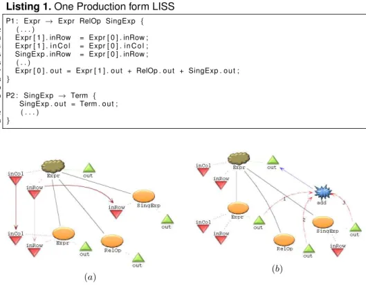
Figure 3.1 shows the visual specification of production P1, taking advantage
of theproduction layout reuse feature, for rapid development and clarity. This
Listing 1.One Production form LISS
1 P1 : Expr → Expr RelOp SingExp {
2 ( . . . )
3 Expr [ 1 ] . inRow = Expr [ 0 ] . inRow ; 4 Expr [ 1 ] . i n C o l = Expr [ 0 ] . i n C o l ; 5 SingExp . inRow = Expr [ 0 ] . inRow ; 6 ( . . )
7 Expr [ 0 ] . o u t = Expr [ 1 ] . o u t + RelOp . o u t + SingExp . o u t ;
8 }
9
10 P2 : SingExp → Term {
11 SingExp . o u t = Term . o u t ;
12 ( . . . )
13 }
(a) (b)
Fig. 1.LISS production onVisualLISA, with associated semantic rules
This way, Figure 3.1 (a) we copy the values from the inherited attributes of
theLHSsymbol to the symbols atRHS; and on another computation associated
with the same production (c.f. Figure 3.1 (b)), we assign a value to theLHS’s
out attribute using a function and the values of other attributes implied in the
production.
4.
VisualLISA: The Environment
VisualLISAeditor should be compliant with the idea of offering a nice and non
error-prone way of sketching theAG, as a first step; and an easy translation of
the model into a target language, as a second step. So, three main features are
highlighted:(i)syntax validation,(ii)semantics verification and(iii)code
syntax-directed. The semantics verification copes with the static and dynamic semantics of the language. Finally, the code generation feature generates code
from the drawings sketched up. The target code would beLISAslorXAGra.
LISAsl specification generated is intended to be passed to LISAsystem in
a straightforward step. XAGra specification generated is intended to give the
system more versatility and further usage perspectives.
5.
Specification of
VisualLISA
The specification ofVisualLISAbases on three main issues:i)the definition
of the underlying language’s syntax; ii) the language semantics and iii) the
description of the textual specifications into which the iconic compositions will be translated.
5.1. Syntax
The Picture Layout Grammar (PLG) formalism [14], is an attribute grammar
to formally specify visual languages. It assumes the existence of pre-defined terminal symbols and a set of spatial relation operators. Our acquaintance with
PLG formalism, from previous works, led us to use it to specify the syntax of
VisualLISA. Listings 2 present some rules of the language specification. For
the sake of space we only present the key rules of the specification; the missing productions are comparable to those shown.
Figure 2 shows the concrete and connector icons used forVisualLISA
specifications.LeftSymbol is theLHSof a production, whileNonTerminal and
Terminal are used to compose the RHS. The second line of icons in Figure 2
presents the several classes of attributes. Function and Identity, both
repre-senting operations, are used to compute the attribute values. The other icons
connect the concrete symbols with each other, to rig up theAG.
Listing 2.VisualLISAPartial Syntax Definition.
1 AG→ c o n t a i n s( VIEW , ROOT) 2
3 VIEW→ l a b e l s(t e x t, rectangle) 4
5 ROOT→ l e f t t o(PRODS, SPECS) 6
7 SPECS→ c o n t a i n s( VIEW , 8 over(LEXEMES, USER FUNCS) ) 9
10 PRODS→ g r o u p o f(SEMPROD) 11
12 SEMPROD→ c o n t a i n s( VIEW , l e f t t o( 13 g r o u p o f(g r o u p o f( RULE ELEM) ) , 14 g r o u p o f(AG ELEM) ) ) 15
16 AG ELEM→LEFT SYMBOL 17 | NON TERMINAL 18 | TERMINAL 19 | SYNT ATTRIBUTE 20 | INH ATTRIBUTE 21 |TREE BRANCH 22 | INT ATTRIBUTE 23 | SYNT CONNECTION 24 | INH CONNECTION 25 | INT CONNECTION
1 RULE ELEM→FUNCTION 2 | IDENTITY 3 |FUNCTION ARG 4 |FUNCTION OUT 5
6 TERMINAL→l a b e l s(t e x t, rectangle) 7
8 INT ATTRIBUTE→ l a b e l s(t e x t,t r i a n g l e) 9
10 INT CONNECTION→ p o i n t s f r o m( 11 p o i n t s t o( 12 d a s h l i n e , 13 ∼INT ATTRIBUTE ) , 14 ∼TERMINAL ) 15
16 FUNCTION→over(rectangle, t e x t) 17
LeftSymbol NonTerminal Terminal
SyntAttribute InhAttribute IntrinsicValueAttribute
Function SyntConnection InhConnection
IntrinsicValueConnection FunctionArg
FunctionOut Identity TreeBranch
Fig. 2.The Icons ofVisualLISA
5.2. Semantics
In order to correctly specify anAG, many semantic constraints must hold. These
constraints are related with the attribute values that depend on the context in which the associated symbols occur in a sentence. We separated these
con-straints into two major groups. One concerning the syntactic rules,Production
Constraints (PC), and another the respective computation rules,Computation
Rules Constraints(CRC).
The following statements are representative constraints ofVisualLISA’s
semantic correctness, concerning the two groups identified before:
PC:The data type of an attribute X.a in a production, must be the same in
any production where X.a occurs.
CRC:The type of the target attribute and the return type of a function, when
they are connected by a FunctionOut symbol, must match.
The complete set of constraints can be seen in [9].
5.3. Translation
The translation (Ls → τ → Lt) is the transformation of a source language
into a target language. τ is a mapping between the productions of the Ls
(VisualLISA) and the fragments ofLt(LISAsl∪ XAGra). These fragments
will be specified in this sub-section.
AContext Free Grammar (CFG) is a formal and robust way of representing
Listing 3.LISAstructure in aCFG.
1 p1: LisaML →language i d{Body}
2 p2: Body →Lexicon A t t r i b u t e s P r o d u c t i o n s Methods 3 p3: Lexicon →lexicon{LexBody}
4 p4: LexBody →( regName regExp )⋆
5 p5: A t t r i b u t e s →a t t r i b u t e s ( t y p e symbol . attName ; )⋆
6 p6: P r o d u c t i o n s →r u l e i d{D e r i v a t i o n} ;
7 p7: D e r i v a t i o n →symbol : : = Symbscompute{SemOperations}
8 p8: Symbs →symbol+
9 p9: | epsilon
10 p10: SemOperations→symbol . attName = O p e r a t i o n ;
11 p11: O p e r a t i o n → . . .
12 p12: Methods →method i d{j a v a D e c l a r a t i o n s}
Reserved words, written in bold, enhance the main fragments in a LISA
sentence, making it more readable. The definition of smaller chunks, introduced by each keyword, enables a more modular processing (code generation. . . )
Regarding the literature, there is not anXMLstandard notation forAGs. So
that,XAGrawas defined using a schema. The whole structure of this schema
can be seen in detail in Section 9.
6.
DEViL
- A Tool for Automatic Generation of Visual
Programming Environments
We searched forVPEgenerators like MetaEdit+ [15], but their commercial
na-ture was not viable for an academic research. Also, we experimented VLDesk [16],
Tiger [17], Atom3
[18] and other similar tools, however none of them gave us
the flexibility thatDEViLoffered, as described below.
TheDEViLsystem generates editors for visual languages from high-level
specifications. DEViL (Development Environment for Visual Languages) has
been developed at the University of Paderborn in Germany and is used in many nameable industrial and educational projects.
The editors generated byDEViL offer syntax-directed editing and all
fea-tures of commonly used editors like multi-document environment, copy-and-paste, printing, save and load of examples. Usability of the generated editors
andDEViLitself can be found in [11].DEViLis based on the compiler
genera-tor framework Eli [19], hence all of Eli’s features can be used as well. Specially the semantic analysis module can be used to verify a visual language instance and to produce a source-to-source translation.
To specify an editor inDEViLwe have to define the semantic model of the
visual language at first. It is defined by the domain specific language DEViL
Structure Specification Language (DSSL) which is inspired by object-oriented
languages and offers classes, inheritance, aggregation and the definition of at-tributes. The next specification step is to define a concrete graphical represen-tation for the visual language. It is done by attaching so called visual patterns
to the semantic model of the VLspecified in DSSL. Classes and attributes of
DSSLinherit from these visual patterns. Visual patterns [20] describe in what
way parts of the syntax tree of theVLare represented graphically, e.g. we can
model that some part should be represented as a “set” or as a “matrix”.DEViL
primitives. All visual patterns can be adapted through control attributes. E.g. we can define paddings or colors of all graphical primitives. Technically visual patterns are decorated to the syntax tree by specifying some easy inheritance rules in a DSL called LIDO.
To analyse the visual language,DEViLoffers several ways. The first one
re-sults from the fact that editors generated byDEViLare syntax directed. Hence,
the user cannot constructwrong instances of theVLIt is limited by its syntax
and cardinalities expressed inDSSL. Another way is to define check rules e.g.
to check the range of an integer attribute or to do a simple name analysis on a
name attribute. To navigate through the structure tree of theVL,DEViLoffers
so called path expressions which are inspired by XPath. They can be used in
a small simple DSL to reach every node in the tree. After analysis,DEViLcan
generate code from the VL instance. This is done with the help of Eli which
offers unparsers, template mechanism (Pattern-based Text Generator— PTG)
and the well-known attribute evaluators from compiler construction.
7.
Implementation of
VisualLISA
To implementVisualLISA, we could have followed a non systematic way,
re-sorting to usual software development methods. But our know-how on compiler construction led us to reuse the systematic generative approach followed in that area. In this case, the implementation process will be supported by the formal
specification made in Section 5, and automated by the VPE chosen, DEViL.
Adopting the standard compiler construction process to the DEViLusage
pe-culiarities, we will follow a four-step process: i) Abstract Syntax Specification; ii) Interaction and Layout Definition; iii) Semantics Implementation; and iv) Code Generation.
7.1. Abstract Syntax
The specification of the abstract syntax ofVisualLISA, inDEViL, follows an
object-oriented notation, as referred previously. This means that the nontermi-nal symbols of the grammar are defined modularly: the symbols can be seen as classes and the attributes of the symbols as class attributes.
The syntax of the visual language is determined by the relations among their symbols. Therefore, for an high level representation of the language’s syntax, a class diagram can be used. This diagram should meet the structure of the
PLGmodel in Figure 2. The final specification for the language is then an easy
manual process of converting the diagram intoDSSL. Figure 3 shows a small
example of the diagram and the resultant specification.
1 CLASS Root{
2 name : VAL V L S t r i n g ;
3 semprods : SUB Semprod∗;
4 d e f s : SUB D e f i n i t i o n s ! ;
5 l i b r a r y : SUB L i b r a r y ? ;
6
}
Fig. 3.Class Diagram and RespectiveDEViLNotation
In order to make possible the specification of separated computation rules
reusing the same layout of a production, we usedDEViL’s concept of coupled
structures [21]. It couples the syntactic structure of two structure tree — for
VisualLISAwe used the structure of symbolSemprod, which is used to model
a production. In practice, it means that the layout defined for a production is replicated whenever a computation rule is defined, maintaining both models synchronized all the time.
7.2. Interaction and Layout
The implementation of this part, inDEViL, consists of the definition of views.
A view can be seen as a window with a dock and an editing area where the language icons are used to specify the drawing.
VisualLISA Editor is based on four views: rootView, to create a list of
productions; prodsView, to model the production layout; rulesView, to specify
the semantic rules reusing the production layout anddefsView, to declare global
definitions of the grammar.
At first the buttons of the dock, used to drag structure-objects into the edition area, are defined. Then the visual shape of the symbols of the grammar for the respective view are defined. Figure 4 shows parts of view definitions and the respective results in the editor. The code on the left side of Figure 4 defines the view, the buttons and the behavior of the buttons. The default action is the in-sertion of a symbol in the editing area. The bluish rectangular image represents the button resultant from that code.
1 VIEW r o o t V i e w ROOT Root{
2 BUTTON IMAGE ” img : : btnProd ” 3 INSERTS Semprod 4 INFO ” P r o d u c t i o n ” ; 5 }
1 SYMBOL pview NonTerminal
2 INHERITS VPForm
3 COMPUTE
4 SYNT . drawing =
5 ADDROF( ntDrawing ) ;
6 END;
Symbol NonTerminal is represented by the orange oval in Figure 4. The code on the right reveals the semantic computation to define the shape of that symbol. Shape and other visual aspects of the tree-grammar symbols are au-tomatically defined associating, by inheritance, visual patterns.
7.3. Semantics
As long asVisualLISAis defined by anAG, the contextual conditions could be
checked using the traditional approach.DEViLis very flexible and offers some
other ways to implement this verification module. The approach used to develop
VisualLISA, is completely focused on the contexts of the generated syntax
tree.DEViLoffers a tree-walker, that traverses the tree and for a given context
— a symbol of that tree — executes a verification code (callback-functions), returning an error whenever it occurs. With this approach it is easy to define data-structures helping the verification process. This approach is very similar to
the genericAGapproach, but instead of attributes and semantic rules, it uses
variables which are assigned by the result of queries on the tree of the model. Listing 4 shows the code for the implementation of a constraint defined in [22].
Listing 4. Implementation of Constraint: “EveryNonTerminal specified in the grammar must be root of one production”
1 c h e c k u t i l : :addCheckSemprod{
2 set n [ l l e n g t h [ c : : g e t L i s t{$ o b j . grammarElements . CHILDREN [ LeftSymbol ]}] ] 3 setsymbName [ c : : g e t{$ o b j . name . VALUE}]
4 i f {$n == 0} {
5 r e t u r n ” P r o d u c t i o n ’ $symbName ’ must have one Root symbol ! ” 6 } e l s e i f{$n>1} {
7 r e t u r n ” P r o d u c t i o n ’ $symbName ’ must have o n l y one Root symbol ! ” 8 }
9 r e t u r n ” ” 10 }
A considerable amount of the constraints defined in Section 5.2 were verified resorting to the Identifier Table, which is a well known strategy in language processing for that purpose.
7.4. Code Generation
The last step of the implementation, concerning the translation of the visualAG
intoLISAorXAGra, can be done using theAGunderlying the visual language
(as usual in language processing). For this task,DEViL supportsi) powerful
mechanisms to ease the semantic rules definition; ii)facilities to extend the
semantic rules by using functions and iii) a template language (PTG of Eli
system) incorporation to structure out the output code.
The use of patterns (templates) is not mandatory. But, as seen in the formal
definition ofLISAandXAGranotation (Section 5.3), both of them have static
parts which do not vary from specification to specification. Hence templates are
very handy here. Even with templates, the translation of the visualAGinto text
is not an easy task. Some problems arise from the fact that there is not a notion
symbols by regarding their disposition over an imaginaryX-axe. Based on this approach we also solved issues like the numbering of repeated symbols in the production definition.
The templates (invoked like functions) and the auxiliary functions, together with other specific entities, were assembled into semantic rules in order to de-fine the translation module. One module was dede-fined for each target notation. New translation modules can be added, to support new target notations.
8.
AG
Specification in
VisualLISA
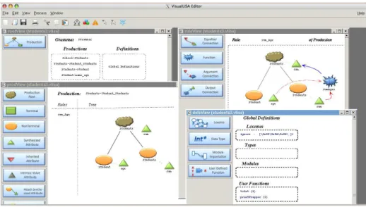
Figure 5 shows the editor look and feel, presenting the four views of our editor.
Fig. 5.VisualLISAEditor Environment
To specify an attribute grammar the user starts by declaring the productions
(inrootView) and rigging them up by dragging the symbols from the dock to the
editing area (in prodsView), as commonly done inVPEs. The combination of
the symbols is almost automatic, since the editing is syntax-directed. When the production is specified, and the attributes are already attached to the symbols, the next step is to define the computation rules. Once again, the user drags
the symbols from the dock, inrulesView, to the editing area, and compounds
the computations by linking attributes to each other using functions. Sometimes it is necessary to resort to user-defined functions that should be described in
defsView. In addition, he can import packages, define new data-types or define
As example we present a simple AG , called Students Grammar, used to process a list of students, described by their names and ages. The objective of
this AGis to sum the ages of all the students. This grammar can be textually
defined as shown in Listing 5.
Listing 5.Students Grammar
1 P1 : Students → Student Students {Students0 . sum = Student . age + Students1 . sum}
2 P2 : Students → Student {Students . sum = Student . age}
3 P3 : Student → name age {Student . age = age . v a l u e}
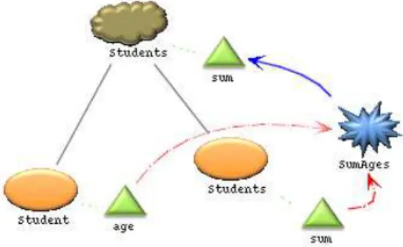
Figures 6 and 7 show the three productions that constitute the grammar. In Figure 6, the attributes are associated with the symbols of the production. Moreover, the production has a semantic rule that computes the value of the
LHS’s attribute,sum, by adding the value of the attributes in theRHSsymbols,
sumandage, using aninlinefunction namedSumAges
Fig. 6.Specification of production P1 with associated semantics
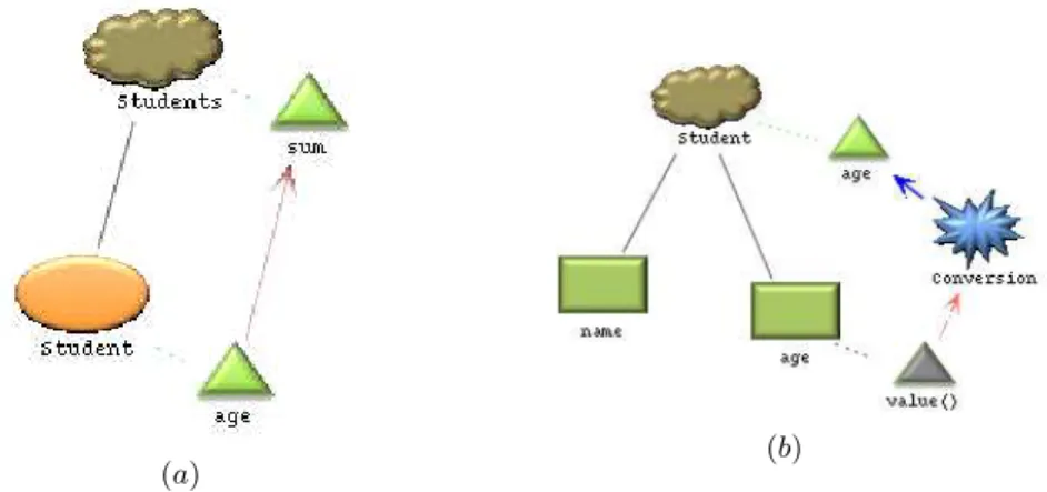
In Figure 7(a), the identity function is used to copy the value of the attribute
age to the attribute sum. In Figure 7 (b), the third production, makes use of
terminal symbols and associated intrinsic values. The computation rule, in this production, is based on the conversion of the textual value of the age into an integer.
When the grammar is completely specified and semantically correct, code
can be generated. Figure 8 shows, in LISA and XAGra notations, the code
generated for productionP1in Figure 6.
9.
X
AGra
- An
XML
dialect for Attribute Grammars
In this section is defined anXML dialect to cope with attribute grammars. We
(a) (b)
Fig. 7.Specification of Productions P2 and P3,(a)and(b)respectively, with associated semantic rules.
(a) (b)
XAGradenotes the abstract representation of anAG. The notation defined
here, is mainly based on the definition ofAGpresented in the Introduction, but
it also borrows parts from the notations inherent to variousAG-based compiler
generator tools.
One of the standardized ways to define a newXMLdialect is the creation
of a schema, using the standardXMLSchema Definition (XSD) language. For
the sake of space, the integral textual definition ofXAGra’s schema is not
pre-sented, and for reasons of visibility and readability, the complete drawing of the schema is broken into several important sub-parts. Figures 9 to 13 are used to support the explanation of the dialect.
XAGra’s root element was defined asattributeGrammar. This element
has a single attribute,name, whose objective is to store the name of the
gram-mar, or the language that the grammar defines; and is a sequence of several elements. These elements represent components of the formal definition of an
AG, incremented with extra parts related to the usage of AG-based compiler
generators.
Table 1 defines a relation of inclusion between theXAGranotation elements
and the components that constitute the formal definition of anAG, which is
re-covered next:
AG= (T, N, S, P, A, R, C,T)
Table 1.Derivation ofXAGraNotation From the Formal Definition ofAG XAGraElement⊇AGComponents
symbols T, N, S
attributesDecl A semanticProds P, R, C,T
importations ∅
functions ∅
The relations depicted in Table 1 give an overview about the information that
each element ofXAGranotation will store. The following sections will describe
with more detail such elements and the information they store.
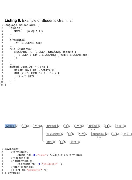
Listing 6 presents a fragment of a grammar that computes the age of a set of students. This example is used to compare the concrete notation of a compiler
generator to theXMLfragments that are shown in the sequent figures.
Next sections present a complete description of the elements of XAGra
scheme. However, the importations andfunctions elements are skipped,
be-cause their structure is simple and similar to the other parts shown.
9.1. Elementsymbols
Figure 9 presents the schema for the elementsymbols. As the name suggests,
Listing 6.Example of Students Grammar
1 language StudentsGra {
2 l e x i c o n{
3 Name [ A−Z ] [ a−z ] +
4 . . . 5 }
6 a t t r i b u t e s
7 i n t STUDENTS. sum ;
8 . . .
9 r u l e S t u d e n t s 1 {
10 STUDENTS : : = STUDENT STUDENTS compute {
11 STUDENTS. sum = STUDENTS [ 1 ] . sum + STUDENT. age ;
12 };
13 }
14 . . .
15 method u s e r D e f i n i t i o n s {
16 i m p o r t j a v a . u t i l . A r r a y L i s t
17 p u b l i c i n t sum ( i n t x , i n t y ){
18 r e t u r n x+y ;
19 }
20 }
21 }
1<symbols>
2 <t e r m i n a l s>
3 <t e r m i n a l i d="name">[ A−Z ] [ a−z ] +</ t e r m i n a l>
4 </ t e r m i n a l s>
5 <n o n t e r m i n a l s>
6 <n o n t e r m i n a l i d="students" />
7 </ n o n t e r m i n a l s>
8 <s t a r t n t ="students" />
9</ symbols>
It is composed of a sequence of three elements:terminals,
nontermi-nalsandstart.
The elementterminalsis a sequence of zero or more elements named
terminal, which, in its turn, has one attribute, id, used to store the name
of a terminal symbol. This attribute is an identifier, hence any instance of it, must be different from the others, and must be always instantiated. Besides the information kept on the attribute, this element has a textual content where the
respectiveRegular Expression(RE) can be declared.
The elementnonterminalshas similar structure. The difference lays on
the fact that it represents a sequence of zero or more elementsnonterminal
which have no textual content. The attributeidhas the same purpose as the
attribute with the same name in the elementterminal.
Finally, the elementstarthas a single attribute namednt. This attribute
is used to refer the nonterminal (already defined in the XAGra specification),
correspondent to the start symbol (or Axiom) of theAG.
9.2. ElementattributesDecl
This element is composed of a sequence of zero or more elements
dec-laration. For the sake of readability, Figure 10 only depicts the structure
of the elementdeclaration, which is a sequence of one or more elements
attribute. This one has three mandatory attributes:i)id– stores the name
of the attribute being declared. Any kind of text can be used to define it, but it
is always better to use the following notation: X.a, whereX is the name of a
symbol inT∪Nandais the name of an attribute inA(X). As it is an identifier, it
must be different from all other identifiers on the specification;ii)type– stores
the data type of the current attribute value andiii)class– defines the class of
the attribute. It must be one of: InhAttribute, SyntAttribute and IntrinsicValueAt-tribute.
1<a t t r i b u t e s D e c l>
2 <d e c l a r a t i o n>
3 <a t t r i b u t e i d="students.sum" type="int" class="SyntAttribute" />
4 </ d e c l a r a t i o n>
5</ a t t r i b u t e s D e c l>
9.3. ElementsemanticProds
The element semanticProdsrepresents the structure to define productions
and associated semantic rules inXAGraspecifications. This structure is
com-posed of a sequence of zero or more elementssemanticProd. Each
seman-ticProdhas one single attribute,name, used to store the mandatory name of
the production, as an identifier.
Element semanticProd has three direct descendants: lhs, rhs,
com-putation, whose structure is explained in the next paragraphs and that are
depicted in Figures 11, 12 and 13.
Elementlhs(Figure 11) is used to refer to the nonterminal symbol on the
LHS of the production. This element has a single attribute,nt, to refer to an
existentnonterminal.
1<l h s n t ="students" />
Fig. 11.XAGraSchema – ElementSemantic Productions:LHSdefinition and example
Elementrhs(Figure 12), stores the nonterminals on theRHSof a
produc-tion. It is composed of a sequence of zero or more elements element. For
this purpose, eachelement, has a single attribute,symbol, which is
manda-tory and represents a reference to a terminal or nonterminal symbol, already
instantiated in the initialsymbolsstructure.
1<r h s>
2 <element symbol="student" />
3 <element symbol="students" />
4</ r h s>
Fig. 12.XAGraSchema – ElementSemantic Productions:RHSdefinition and example
Elementcomputation(Figure 13) is the last child of the element
seman-ticProds. It represents an hard concept ofAGs: the semantic rules.
This element has one attribute,name, used to give a name to the
compu-tation being declared. This attribute, despite being mandatory, is not a unique identifier: different computations can have equal names.
The structure ofcomputationrepresents a pure abstraction of what is a
1<computation name="getTheSum">
2 <a s s i g n e d A t t r i b u t e a t t ="students.sum" p o s i t i o n ="0" />
3 <o p e r a t i o n r e t u r n T y p e ="int">
4 <argument a t t ="student.age" p o s i t i o n ="1" />
5 <argument a t t ="students.sum" p o s i t i o n ="2" />
6 <modus> $1 + $2</ modus>
7 </ o p e r a t i o n>
8</ computation>
Fig. 13.XAGraSchema – ElementSemantic Productions:Computationdefinition and example
the operation that computes this value. Thus, the elementcomputationhas
two children: the elementsassignedAttributeandoperation.
ElementassignedAttributeis composed of two mandatory attributes:
att, which is used to refer to an attribute; andposition, which is a number
that identifies the position of the symbol associated to the attribute in the list
of elements of the production. That is, if the attribute is connected to theLHS,
then the value forpositionmust be 0. If the associated symbol belongs to the
RHS, then its value should correspond to the position that the symbol occupies
in theRHSsequence of symbols, starting with 1.
The elementoperationaggregates a sequence of zero or more elements
argumentand a single elementmodus. In addition to the elements, it has an
attribute,returnType, used to store the data type of the value returned by the
operation.
Elementsargumentare, in all aspects, equal to theassignedAttribute
element. Each one has two attributes with the same name and the same se-mantic value underlaying, therefore they are used to refer to previous declared attributes. The difference is on the fact that this time, the attributes referenced are those used to compute the value in the operation.
The last element,modus4, which is a simple text field to write the expression
used to compute the value. Somehow, in this element’s text, a reference to the argument attributes should be made. An example (and the convention
estab-lished) is using$x, wherex >0is the position of the attribute in the sequence
of arguments.
Aside theimportationsand thefunctionsparts, theXAGra’s schema is now completely defined and explained, revealing the universality needed to store
anyAGfor anyAG-based compiler generator.
Next section briefly presentsXAGraAl, demonstrating one interesting
ap-plicability of theXAGradialect.
10.
Conclusion
After many years working in specification and implementation of compilers
sup-ported by Attribute Grammars, it became clear that a modular and reusable
approach toAGdevelopment is highly recommendable and necessary. On the
other hand, the work on program comprehension tools emphasized the impor-tance of software/data visualization. The combination of those two areas of R&D
with a third one, the development ofVisual Languages, gave rise to the proposal
of creating aVLforAGs, since there are no other tools allowing it, according to
our knowledge. The obligation to write text-basedAGspecifications imposed by
several compiler generator tools and the habitual way of sketchingAGs on paper
in the form of a decorated tree, shortening the gap to the mental representation
of anAG, reinforced the appropriateness of that proposal.
In this paper we introducedVisualLISA, a newDomain Specific Visual
Language, which enables the specification ofAGs in a visual manner and the
translation of that visualAGinto LISAor XAGra(anXMLnotation to support
genericAGspecifications).XAGraallows us to use this visual editor with other
compiler-compiler tools.
We were mainly concerned with the design of the language, its formal and automatic implementation. In this phase of our project we neither focused on the usability of the language nor on its scalability. We focused on the spec-ification, aiming at showing the formal work behind the visual outcome, and
on the implementation of the underlying environment to specify AGs. At this
point we highlighted the use of DEViLin order to create the desired
environ-ment, through a systematic approach of development. Also, an example was
presented to show the steps to build anAGwithVisualLISA.
In the future, it is our objective to perform at least, two experimental studies
involving VisualLISA: one to assess the usability of the language regarding
the visual vs textual approaches for developing AGs; and another one to test
the scalability of the language and environment, regarding the hypothesis that
it was created to cope with small AGs. We are also interested in assessing
the comprehension of AGs; maybeVisualLISAwould be very handy on this
matter, working asAGs visualizer.
Concerning the applicability ofXAGra, we can translate it into the specific
notation of any compiler generator tool. We call XAGra loader to the
pro-gram that performs this translation. As future work, the following translators
are planed:XAGraintoLISA(a traditional LR parser generator);XAGrainto
intoEli(an LR parser generator with special constructors). Finally, a translator
fromXAGratoYacccould be a challenging project.
Also, we developed aGrammar Analyzer and Transformationtool,XAGraAl.
that takes as input anAGwritten inXAGra. Thus, the implementation of this tool
shows the applicability ofXAGraas a universal and multi-purposeAG
specifi-cation language.
References
1. Pereira, M.J.V., Mernik, M., da Cruz, D., Henriques, P.R.: VisualLISA: a visual inter-face for an attribute grammar based compiler-compiler (short paper). In: CoRTA08 — Compilers, Related Technologies and Applications, Braganc¸a, Portugal. (July 2008)
2. Boshernitsan, M., Downes, M.: Visual programming languages: A survey. Technical report, University of California, Berkeley, California 94720 (December 2004) 3. Kastens, U., Schmidt, C.: VL-Eli: A generator for visual languages - system
demon-stration. Electr. Notes Theor. Comput. Sci.65(3) (2002)
4. Costagliola, G., Tortora, G., Orefice, S., De Lucia, A.: Automatic generation of visual programming environments. Computer28(3) (1995) 56–66
5. Mernik, M., Leniˇc, M., Avdiˇcauˇsevi´c, E., ˇZumer, V.: LISA: An interactive environment for programming language development. Compiler Construction (2002) 1–4 6. Mernik, M., Korbar, N., ˇZumer, V.: LISA: a tool for automatic language
implementa-tion. SIGPLAN Not.30(4) (1995) 71–79
7. Henriques, P.R., Pereira, M.J.V., Mernik, M., Leniˇc, M., Gray, J., Wu, H.: Automatic generation of language-based tools using the lisa system. Software, IEE Proceed-ings -152(2) (2005) 54–69
8. Parr, T.: The Definitive ANTLR Reference: Building Domain-Specific Languages. First edn. Pragmatic Programmers. Pragmatic Bookshelf (May 2007)
9. Solutions, U.: Ultragram - parser generator. http://www.ultragram.com/ (January 2010)
10. NorKen Technologies, I.: Programmar. http://www.programmar.com (January 2010) 11. Schmidt, C., Cramer, B., Kastens, U.: Usability evaluation of a system for implemen-tation of visual languages. In: Symposium on Visual Languages and Human-Centric Computing, Coeur d’Al `ene, Idaho, USA, IEEE Computer Society Press (September 2007) 231–238
12. Ikezoe, Y., Sasaki, A., Ohshima, Y., Wakita, K., Sassa, M.: Systematic debugging of attribute grammars. In: AADEBUG. (2000)
13. da Cruz, D., Henriques, P.R.: Liss — the language and the compiler. In: Proceed-ings of the 1.st Conference on Compiler Related Technologies and Applications, CoRTA’07 — Universidade da Beira Interior, Portugal. (Jul 2007)
14. Golin, E.J.: A Method for the Specification and Parsing of Visual Languages. PhD thesis, Brown University, Department of Computer Science, Providence, RI, USA (May 1991)
15. Tolvanen, J.P., Rossi, M.: Metaedit+: defining and using domain-specific modeling languages and code generators. In: OOPSLA ’03: Companion of the 18th annual ACM SIGPLAN conference on Object-oriented programming, systems, languages, and applications, New York, NY, USA, ACM (2003) 92–93
17. Ehrig, K., Ermel, C., H ¨ansgen, S., Taentzer, G.: Generation of visual editors as eclipse plug-ins. In: ASE ’05: Proceedings of the 20th IEEE/ACM international Con-ference on Automated software engineering, New York, NY, USA, ACM Press (2005) 134–143
18. de Lara, J., Vangheluwe, H.: Atom3: A tool for multi-formalism and meta-modelling. In: FASE ’02: Proceedings of the 5th International Conference on Fundamental Ap-proaches to Software Engineering, London, UK, Springer-Verlag (2002) 174–188 19. Gray, R.W., Heuring, V.P., Levi, S.P., Sloane, A.M., Waite, W.M.: Eli: A complete,
flexible compiler construction system. Communications of the ACM35(2) (February 1992) 121–131
20. Schmidt, C., Kastens, U., Cramer, B.: Using DEViL for implementation of domain-specific visual languages. In: Proceedings of the 1st Workshop on Domain-Specific Program Development, Nantes, France (July 2006)
21. Schmidt, C.: Generierung von Struktureditoren f ¨ur anspruchsvolle visuelle Sprachen. Dissertation, Universit ¨at Paderborn (January 2006)
22. Oliveira, N., Pereira, M.J.V., da Cruz, D., Henriques, P.R.: VisualLISA. Techni-cal report, Universidade do Minho (February 2009)www.di.uminho.pt/˜gepl/ VisualLISA/documentation.php.
23. GlassFish: Java architecture for XML binding. https://jaxb.dev.java.net/ (June 2009)
24. GlassFish: Java API for XML processing.https://jaxp.dev.java.net/(June 2009)
25. da Cruz, D., Oliveira, N., Henriques, P.R.: Graal - a grammar analyzer (September 2009) Available at:http://inforum.org.pt/INForum2009/programa.
A.
X
AGraAl
: A grammar analyzer based on
X
AGra
In this section we give a brief introduction toXAGraAl, aGrammar Analyzer
and Transformation tool that computes dependencies among symbols,
gram-mar metrics, and gramgram-mar slices for a given criterion; moreover,XAGraAlcan
also derive, from the original, shorter grammars combining slices or removing
unitary productions (similar to re-factoring a program).XAGraAltakes as input
anAGwritten inXAGra.
XAGraAlis a platform independent tool, developed using Java. Java
Archi-tecture for XML Binding (JAXB) [23] and Java API for XML Processing (JAXP) [24]
were used to process the input.
While parsing aXAGragrammar using JAXB,XAGraAlbuilds the
identi-fiers table (IdTab) where it collects all grammar symbols and attributes; each
identifier is associated with all its characteristics extracted or inferred from the
source document. The identifiers table — that can be pretty-printed inHTML—
complemented by the dependence graph (DG) — also printable usingDotand
GraphViz— constitute the core of the tool. Traversing those internal
represen-tation structures, it is possible to implement the otherXAGraAlfunctionalities:
– Metrics, to assess grammar quality;
– Slicing, to ease the analysis producing sub-grammars focussed in a specific
– Re-factoring, to optimize grammars generating smaller and more efficient versions.
Metricsare organized in three groups of assessment parameters:
– Size metrics, that measure the number of symbols, productions, and so on
(grammar and parser sizes);
– Form metrics, that describe the recursion pattern and measure the
depen-dencies between symbols (the grammar complexity);
– Lexicographic metrics, that qualify the clearness/readablity of grammar
iden-tifiers, based on a domain ontology.
Slicing operation builds partial grammar with the elements that derive in zero
or more steps on the criterion (backward slicing), or that are reachable from the criterion (forward slicing). The criterion can be either a symbol or an attribute. Slices are usually presented as paths over the dependence graphs. Figures 14
(a)and(b)illustrate a forward and a backward slice w.r.t the symbolage.
(a) (b) (c)
Fig. 14.Slices with respect to symbolage: (a)Forward slice;(b)Backward slice and(c) Combination of Forward and Backward slices
Re-factoringis a not so usual functionality that transforms the original
gram-mar into a minimal one, removing all the useless productions. Another
trans-formation also provided is the generation of a new grammar combining forward
and backward slices with respect to the same symbol (see Figure 14(c)).
Built in a similar way, GraAL [25] accepts as input a grammar written in
AntLR 3and produces the same outputs. However,XAGraAlbeatsGraALin
guage Processing group at CCTC (Computer Science and Technology Center), University of Minho. He participated in several projects with focus on Visual Languages and Program Comprehension; VisualLISA and Alma2 the main out-come of his master thesis entitled ”Program Comprehension Tools for Domain-Specific Languages”, are the most relevant works. The latter came under ”Pro-gram Comprehension for Domain-Specific Languages”, a bilateral project be-tween Portugal and Slovenia, funded by FCT. Currently, he is starting his PhD studies on Patterns for Architectures Coordination Analysis and Self-Adaptive Architectures, under MathIS, a research project also funded by FCT. Mean-while he is an assistant-lecturer (practical classes) in a course on Imperative Programming, at University of Minho.
Maria Jo ˜ao Varanda Pereira, received the M.Sc. and Ph.D. degrees in com-puter science from the University of Minho in 1996 and 2003 respectively. She is a member of the Language Processing group in the Computer Science and Technology Center , at the University of Minho. She is currently an adjunct professor at the Technology and Management School of the Polytechnic In-stitute of Braganc¸a, on the Informatics and Communications Department and vice-president of the same school. She usually teaches courses under the broader area of programming: programming languages, algorithms and lan-guage processing. But also some courses about project management. As a researcher of gEPL, she is working with the development of compilers based on attribute grammars, automatic generation tools, visual languages and pro-gram understanding. She was also responsible for PCVIA project (Propro-gram Comprehension by Visual Inspection and Animation), a FCT funded national research project; She was involved in several bilateral cooperation projects with University of Maribor (Slovenia) since 2000. The last one was about the subject “Program Comprehension for Domain Specific Languages”.
data-mining, and data-cleaning. He is co-author of the “XML & XSL: da teoria a pr ´atica” book, published by FCA in 2002; and has published 3 chapters in books, and 20 journal papers.
Daniela da Cruz, received a degree in “Mathematics and Computer Science”, at University of Minho, and now she is a Ph.D. student of “Computer Science” also at University of Minho, under the MAPi doctoral program. She joined the re-search and teaching team of “gEPL, the Language Processing group” in 2005. She is teaching assistant in different courses in the area of Compilers and For-mal Development of Language Processors; and Programming Languages and Paradigms (Procedural, Logic, and OO). As a researcher of gEPL, Daniela is working with the development of compilers based on attribute grammars and automatic generation tools. She developed a completed compiler and a vir-tual machine for the LISS language (an imperative and powerful programming language conceived at UM). She was also involved in the PCVIA (Program Comprehension by Visual Inspection and Animation), a FCT funded national research project; in that context, Daniela worked in the implementation of “Alm”, a program visualizer and animator tool for program understanding. Now she is working in the intersection of formal verification (design by contract) and code analysis techniques, mainly slicing.
Bastian Cramer, received his degree in Computer Science from the University of Paderborn, Germany in 2005. Then he joined the research group ’Program-ming Languages and Compilers’ of Prof. Kastens at the same university. His research focus is the generation of software from specifications and especially the generation of environments for visual domain specific languages. He has several years of experience in language design in corporation with the auto-motive industry. Currently he is working on his PhD concerning simulation and animation of visual languages.