IUL School of Technology and Architecture Department of Information Science and Technology
Light Field Processor:
A Lytro Illum imaging application
Agostinho Silva
A Dissertation presented in partial fulfilment of the Requirements for the Degree of Master in Computer Science Engineering, Multimedia Specialisation
Supervisor:
PhD Paulo Nunes, Assistant Professor ISCTE-IUL
Acknowledgments
I would like to thank my dear friendPaulo Tavares de Almeida
for his continuous support, without which this work would not have been possible.
I would also like to thank the expert comments and tips given by Maria Henriqueta Tavares de Almeida
João Luis Pimentel Nunes Marco Gaspar
who contributed to the enrichment of this work.
Finally, a special thanks to Professor Paulo Nunes
for his humble and simple nature, which made me feel comfortable when interacting with him and certainly made a lot of things, a lot easier.
Dedicated to the memory of my father Augusto José da Silva Rêgo
who abandoned this world in July 2015,
just when I was about to start the development stage of this work.
Light Field Processor was partially developed under a scholarship of the 3D-SERVICIS project granted by
Instituto de Telecomunicações (IT) – Lisbon, Portugal The author acknowledges the support of
Fundação para a Ciência e Tecnologia, under the project UID/EEA/50008/2013
A tecnologia de imagem de campo de luz está na intersecção de três grandes áreas de investigação: gráficos por computador, fotografia computacional e visão por computador. Esta tecnologia tem o potencial de possibilitar funcionalidades que eram anteriormente impraticáveis, senão mesmo impossíveis, tais como refocar imagens fotográficas após a captura ou movimentar-se numa cena de RV produzida por um motor de jogos em tempo real, com 6 graus de liberdade.
A fotografia tradicional produz uma única saída sempre que um utilizador prime o botão de disparo. A fotografia campo de luz pode ter várias saídas diferentes porque junta muito mais dados acerca da cena. Logo ela requer pós-processamento por forma a extrair qualquer informação útil, como imagens 2D, e essa é uma funcionalidade caracterizante desta tecnologia que a torna substancialmente diferente de todas as outras no ramo da produção de imagem.
Pós-processamento significa usar uma aplicação especializada e, uma vez que esta tecnologia ainda está na sua infância, essas aplicações são escassas. Este contexto proporcionou uma boa oportunidade para tal desenvolvimento.
Light Field Processor é o principal resultado deste trabalho. É uma aplicação para computador capaz de abrir e descodificar imagens de cameras Lytro Illum campo de luz, que podem então ser armazenadas como um novo formato de ficheiro (Campo de Luz Descodificado), proposto nesta dissertação, para uso posterior. É capaz de extrair pontos de vista 2D, mapas 2D de pontos de vista ou conjunto de microlentes, vídeos mostrando a paralaxe intrínseca do campo de luz e metadados, assim como fazer algum processamento de imagem básico.
Palavras-chave: Campo de Luz, Processamento de Imagem, Fotografia Computacional, Lytro Illum.
Abstract
Light field imaging technology is at the intersection of three main research areas: computer graphics, computational photography and computer vision. This technology has the potential to allow functionalities that were previously impracticable, if not impossible, like refocusing photographic images after the capture or moving around in a VR scene produced by a real-time game engine, with 6DoF.
Traditional photography produces one single output whenever a user presses the shot button. Light field photography may have several different outputs because it collects much more data about a scene. Thus it requires post-processing in order to extract any piece of useful information, like 2D images, and that is a characteristic feature that makes this technology substantially different from all others in the field of image making.
Post processing means using a specialised application and, since this technology is still in its infancy, those applications are scarce. This context presented a good opportunity for such a development.
Light Field Processor is the main outcome of this work. It is a computer application able to open and decode images from Lytro Illum light field cameras, which it may then store as a new file format (Decoded Light Field), proposed in this dissertation, for later use. It is able to extract 2D viewpoints, 2D maps of viewpoints or the microlens array, videos showing the intrinsic parallax of the light field and metadata, as well as do some basic image processing.
Keywords: Light Field, Image Processing, Computational Photography, Lytro Illum.
D
I S S E R T A T I O N
C
ONTENTS
1.
I
NTRODUCTION... 1
1.1. Context and Motivation ... 1
1.2. Goals ... 3
1.2.1. Application requirements and features ... 3
1.2.2. Target users ... 3
1.3. Methodologies ... 4
1.3.1. Application development ... 4
1.3.2. Dissertation ... 5
1.3.3. This document’s readability ... 6
1.4. Main Contributions of This Work ... 7
1.4.1. Application features perspective ... 7
1.4.2. Application development perspective ... 7
1.5. Quick Overview of Contents ... 8
2.
H
OWP
HOTOGRAPHYW
ASB
ORN... 9
2.1. The Birth of a New Technology ... 10
2.1.1. The term ... 10
2.1.2. How photography came into existence ... 11
2.2. The First Photocopy Office ... 12
2.3.1. Maxwell: Validation of the trichromatic theory ... 13
2.3.2. Hauron: First implementation of the three-colour method... 15
2.3.3. Lippmann: A different approach to colour ... 16
2.3.4. Ives: Avoiding printed paper ... 16
2.3.5. And the winners are: the Leopold musicians! ... 17
2.4. The Modern Era ... 18
2.4.1. Developments leading to light field photography ... 19
2.4.2. Current light field cameras ... 19
3.
L
IGHTF
IELDI
MAGINGC
ONCEPTS... 21
3.1. Human Vision ... 22
3.1.1. Binocular vision ... 22
3.1.2. Stereoscopy ... 22
3.1.3. Binocular disparity and stereopsis ... 22
3.1.4. Sensing light ... 23
3.1.5. Interpreting light ... 23
3.2. Light Field Theory Overview ... 24
3.2.1. The plenoptic function ... 24
3.2.2. Radiance ... 25
3.2.3. Light field ... 25
3.3. Light Field Image Formation ... 25
3.3.1. Brief overview of a light field camera ... 25
3.3.2. Light field image ... 27
3.4. Light Field Image Processing ... 28
3.4.1. Decoding ... 29 3.4.2. Viewpoint ... 29 3.4.3. White image ... 30 3.4.4. Depth of field ... 30 3.4.5. Depth of focus ... 31 3.4.6. All-in-focus ... 31 3.4.7. Refocusing ... 31 3.4.8. Vignetting ... 31
4.
L
IGHTF
IELDP
ROCESSOR... 33
4.1. What is Light Field Processor? ... 34
4.1.1. LFR related outputs ... 35
4.1.2. DLF related outputs ... 35
4.2. LF Processor: Usability ... 36
4.2.1. Obtaining help inside the application ... 36
4.2.2. Application folders... 37
4.2.3. Automatic naming scheme for exported files ... 38
4.2.4. Validation of user inputs ... 39
4.2.5. Running LF Processor for the first time ... 39
4.3. LF Processor: Graphical Interface ... 41
4.3.1. Main screen ... 41 4.3.2. Main workspace ... 42 4.3.3. LFR workspace ... 43 4.3.4. DLF workspace ... 43 4.4. LF Processor: Features ... 45 4.4.1. File menu ... 45 4.4.2. Process menu ... 46
4.4.3. Process menu: Decode ... 47
4.4.4. Process menu: Image (processing) ... 48
4.4.5. Process menu: Depth Filters (engine) ... 50
4.4.6. Export menu ... 54
4.4.7. View menu ... 56
4.4.8. Other operations ... 56
5.
D
EVELOPMENT OFLF
P
ROCESSOR... 57
5.1. Software Development Methodology ... 58
5.1.1. Requirements ... 58
5.1.2. Design, Implementation and Testing ... 60
5.1.3. Deployment ... 60
5.2. Application Architecture ... 61
5.2.2. Internal architecture ... 62
5.3. Programming ... 67
5.3.1. DLF data structure ... 67
5.3.2. Paradigm adopted ... 68
5.3.3. How to save the DLF file’s exact size on disk, within itself ... 69
5.4. Development Tools and Contents ... 70
5.4.1. Matlab: programming language and editor ... 70
5.4.2. Application dependencies: Light Field Toolbox ... 70
5.4.3. Photoshop: Image editing ... 70
5.4.4. Light field image datasets used ... 70
5.5. Extra Work That Was Not Used ... 71
6.
C
ONCLUSIONS... 73
6.1. Contributions of This Work ... 73
6.1.1. LF Processor ... 74
6.1.2. XSL template for automatic bibliographic sources ... 75
6.2. Future Work ... 76
B
IBLIOGRAPHY... 77
A.
A
PPENDIXA:
A
PPLICATIOND
EPLOYMENT... 85
A.1. Application Versions ... 85
A.1.1. Dependent application ... 85
A.1.2. Standalone application ... 86
A.2. Installing LF Processor ... 86
A.2.1. As a dependent application ... 86
A.2.2. As a standalone application ... 87
L
I S T O F
F
IGURES
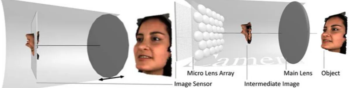
Figure 1 – Overview of the software development methodology used: Iterative mini-Waterfalls. ... 5 Figure 2 – Hercule Florence, around the age of 70 [25]. ... 10 Figure 3 – The oldest surviving photograph taken around 1826 by J. Niépce [30]. 11 Figure 4 – Photocopy of a Diploma made by H. Florence around 1839 [25]. ... 12 Figure 5 - Left: Colour triangle shown on Maxwell’s paper [34]. Right: A modern depiction of the colour triangle and colour disc envisioned by Maxwell using real colours [37]. ... 14 Figure 6 – Depiction of three colour filtered plates that allowed the reproduction of a colour image for the first time, using the trichromatic process (adapted from [38]). ... 14 Figure 7 – An 1877 photograph using Hauron’s method [39]. ... 15 Figure 8 – Colour photograph from the 1890s using the interference method [44]. ... 16 Figure 9 – Vase of Flowers: A Kromogram of 1897 [46]. ... 17 Figure 10 – A Kodachrome picture by Chalmers Butterfield [45]. ... 18 Figure 11 – Effects of horizontal disparity on binocular vision (original creation from parts of [4]). ... 22 Figure 12 – Light rays reflected off an apple [4]. ... 23 Figure 13 – Parameterization of the 5D Plenoptic function [62]. ... 24 Figure 14 – A light field represents the amount of energy across a tubular area [62]. ... 25 Figure 15 – Left: Conventional 2D camera (lens focuses directly onto image sensor). Right: Light field camera (lens generates intermediate image, which is then focused by the Microlens Array onto the image sensor) (adapted from [64] and [5]). ... 26
Figure 16 – A light field camera captures angular information (adapted from [4]).
... 27
Figure 17 – Parameterization of a light field using two planes (adapted from [66]). ... 27
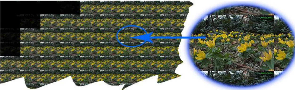
Figure 18 – An amplified slice of a raw light field image. ... 28
Figure 19 – A cut on a Views Map emphasising an amplified Viewpoint. ... 29
Figure 20 – Amplified sample of a White Image shown by LF Toolbox while decoding [13]. ... 30
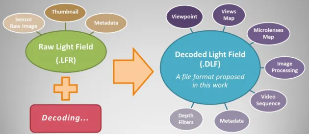
Figure 21 – Processing flow of the Light Field Processor application, emphasising its main functional purpose and outputs. ... 34
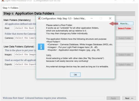
Figure 22 – Initial Configuration procedure - Step 1: Application Data Folders. ... 37
Figure 23 – Button Tooltips. ... 37
Figure 24 – Application folders structure showing the exported contents of the “Flowers” light field image. ... 38
Figure 25 – Crucial information before configuring LF Processor. ... 40
Figure 26 – Light Field Processor main screen, just after launch. ... 41
Figure 27 – Presentation of the Toolbar. ... 41
Figure 28 – Main screen and workspace after opening an LFR file. ... 42
Figure 29 – A Data Cursor tip... 43
Figure 30 – Main screen and workspace after opening a DLF file. ... 44
Figure 31 – The Viewpoint Navigator... 44
Figure 32 – Potentially problematic data shown in red. ... 45
Figure 33 – Open Light Field dialogue box and the File menu. ... 45
Figure 34 – Preferences: Image Processing options screen. ... 48
Figure 35 – Comparison of image processing tasks. Left: original DLF without any effects; Centre: applied CC (R=1.00, G=1.00, B=1.00); Right: applied CC+GC+HE+IB (all with default values). ... 49
Figure 36 – Example of the Improve Borders (IB) feature... 50
Figure 37 – Depth Filters submenu options... 51
Figure 38 – Preferences: Depth Filters options screen; (each operation’s initialism is highlighted with a red border). ... 51
Figure 39 – Depth Filters engine: running the Shift Sum filter (the front image is defocused as a direct consequence of the application of the filter). ... 52
Figure 40 – Depth Filters engine: generated folder structure and file naming scheme. ... 53
Figure 41 – Results of applying the Shift Sum filter to DLF file “Friends_1”, with a growth of +0.50 per iteration of the slope parameter. Left: [03] SS(slope=-0.50); Centre: [04] SS(slope=0.00); Right: [05] SS(slope=0.50). ... 54
Figure 42 – Preferences: File Input/Output options screen. ... 55
Figure 43 – Detailed software development methodology used: Iterative mini-Waterfalls. ... 58
Figure 44 – External architecture of LF Processor, using a simplified approach. .... 61
Figure 46 – Folder structure of the project’s files. ... 62 Figure 47 – Example of code from the Action Class, used mainly as a powerful data structure. ... 63 Figure 48 – Diagram of the application Configuration data structures (numbers are respective to the tab used in the Configuration screen). ... 64 Figure 49 – Application Configuration: Cameras Management screen. ... 64 Figure 50 – Diagram of the application Preferences data structure (numbers are respective to the tab used in the Preferences screen). ... 65 Figure 51 – Using GUIDE to visually design the DLF data panel. ... 66 Figure 52 – Workspace panel (left): Top level of the internal data structure of a DLF file. Command Window (right): contents of some DLF fields. ... 67 Figure 53 – Matlab’s console showing a DLF file ipTasks variable and its contents. ... 68 Figure 54 – List of the 30 files used for Class definitions. ... 69 Figure 55 – Step 3 of Application Configuration: White Images Database update. . 88
L
I S T O F
A
CRONYMS
2D Two-dimensional; or regarding two dimensions 3D Three-dimensional; or regarding three dimensions 4D Four-dimensional; or regarding four dimensions 5D Five-dimensional; or regarding five dimensions 6D Six-dimensional; or regarding six dimensions
6DoF Six Degrees of Freedom (in the context of Virtual Reality) CC Colour Correction
CCM Colour Correction Matrix
DLF Decoded Light Field image
.DLF/.dlf DLF file name extension; or regarding the data contained in such file
DoF Depth of Field
GC Gamma Correction
GUI Graphical User Interface
HE Histogram Equalisation (also Histogram Equalization)
HVS Human Visual System
IB Improve Borders
IDE Integrated Development Environment
IT Information Technology
LF Light Field
LFR Light Field Raw image: standard output file of a Lytro Illum camera .LFR/.lfr LFR file name extension; or regarding the data contained in such file MLA Microlens Array (also Micro Lens Array)
VR Virtual Reality
WID White Images Database
NOTE: The abbreviation LF Processor is used extensively throughout this work to refer to the Light Field Processor software application. We do not use the acronym LFP simply because it could be confused with the file type LFP (Light Field Picture) that Lytro defined as the raw light field image file type for its first generation cameras (F1) and also as a container file type for the Lytro Illum camera, which is the main focus of this work.
C
H A P T E R
1
1.
I
NTRODUCTION
Writing an introduction is like filling a bottle of water through a funnel.
No matter how much content you have or how good it may be, it will always have to be small enough to fit in the bottle and flexible enough to pass through the funnel.
While funnelling my thoughts…
1.1. Context and Motivation
The trend towards automated systems (e.g. auto-driven vehicles) has led to the increased demand for ways to automatically interpret images and extract information like positioning and target detection, amongst other things.
3D reconstruction from 2D images has long been a well-known problem in the scientific community and new and better ways to achieve it have been developed. One of the main inputs required is the knowledge about the depth of objects in the scene. In traditional photography, a single (mono) image may be sufficient to infer depth but it requires more complex algorithms than the ones required by stereo methods using a pair of images [1].
However, this apparently simple requirement of extraction of depth information from the visual scene poses a problem when capturing scenes with camera or object motion, because all images must be taken at the exact same time, so that only the angle of view is changed and not the positioning of objects on the scene. Moreover, having more than two perspectives may provide even more reliable results and simpler algorithms but requires further data to process and more complex capture devices. Still, that seemed like the right path to go and some systems were created that allow the capture of such still images.
Stanford University, in the USA, has been pioneering the development of light field image capture systems. Two examples are the Multi-Camera Array [2] and the Spherical Gantry [3]. Unfortunately, those systems are not portable, so they cannot be easily carried around to capture nature scenes, for instance. Besides that, setting those systems up requires a lot of expertise and resources, which also makes them unaffordable for a common user, contrary to any conventional photographic camera [4].
A silent revolution began when a new approach was used to create an array, not of cameras, but of tiny lenses that could allow the capture of hundreds of tiny images at the same time, from the same scene, with slight changes of perspective. This is the architecture of current portable light field cameras from Raytrix [5] and Lytro [6], [7] which is setting the standards for this technology.
Light field imaging technology is at the intersection of three main research areas:
Computer Graphics;
Computational Photography;
Computer Vision.
Implicitly, this also includes knowledge on a variety of other fields of study such as human vision, software development and geometry, to name just a few. Therefore, this is clearly a multi-disciplinary technology and that fact makes it difficult to understand at first. However, it has the potential to allow functionalities that would otherwise not be possible (or at least would be much more complicated to build), like refocusing photographic images after the capture (post focusing) [8], [7]; or seeing around 360° in virtual scenes using systems like “Moon”, a 6DoF VR system developed by Lytro [9] which promises a revolution in the field.
Perhaps the one single characteristic of this technology that makes it harder to absorb by a casual user is the fact that it requires post-processing in order to extract useful information like 2D images, and that means having to use a specialised software application. Since this technology is still in its infancy, these applications are scarce.
We interpreted this context as a good opportunity to develop such an application and this work is the outcome of such effort.
1.2. Goals
1.2.1. Application requirements and features
Since Lytro was the first company to launch a Light Field camera geared towards the consumer market, a few free software packages to process its images soon appeared. However, the launch of its second generation on July 2014, named Lytro Illum [10], improved and changed several aspects of how the technology was used. The change in file format and its bit packing scheme (12-bit for version 1 and 10-bit for version 2) made the output from both cameras incompatible and, with it, all the software developed for the first generation. The image resolution and aspect ratio are also different. Such major changes made developers cautious about investing more resources on future developments which lead to most of that software [11] not being updated to the latest format. Some of the few free packages that were updated included Lytro Desktop, which is the proprietary software package that Lytro developed to process the light field images from its cameras [12] and a library of functions written for Matlab, called Light Field Toolbox, developed by Donald Dansereau [13]. The latter, although having some very useful functions, requires the user to have some technical expertise and programming skills. It also requires that resources and workflow be managed manually by the user because it is not an application and it does not have a Graphical User Interface (GUI).
Therefore, we identified an opportunity and momentum to:
Develop a free application with a GUI that could automate some tasks in the light field image processing workflow (e.g. cameras management);
Integrate features that could be useful to both technicians and end users;
Move the focus towards the scientific side of the technology, which is more appealing to researchers and students of this technology.
Those tasks became the main goals of this work and that led to the design and implementation of the Light Field Processor (LF Processor) software application.
1.2.2. Target users
The target group of users for the LF Processor software application is primarily constituted by researchers and students interested in light field photography and related technologies, but it may also include any user of a Lytro Illum light field camera. The dissertation may be of interest to even more user profiles, such as project managers and software architects or developers, due to Chapter 5 which is more oriented towards the IT field.
In practice this may encompass people from a wide range of areas of expertise, which represented a huge challenge in the development of this work and required special caution in the way to interact with and convey information to this target
audience, through the application and the dissertation respectively, as will be explained throughout this document whenever needed.
1.3. Methodologies
1.3.1. Application development
Considering that some of the target audience of this work may not have had formal training in software engineering and its theory, a few technical remarks are due for the sake of clarity.
It is important to notice that a software application should not be misinterpreted as an algorithm or a process; usually, at least in terms of scope, an application is much more than that. It ought to be understood as a whole functional unit, which may be constituted by many modules or components, which are themselves built with algorithms used to process data towards achieving predetermined goals. An application is driven by the user, whilst a process is driven by the developer who programmed it, which implies that only the latter may be expressed in terms of a work flow diagram, simply because user actions, such as deciding which process to execute through menu options, are made in application running time, not in development time when any diagram is built.
The author of this work follows the definition of Software Architecture presented by Bass, Clements and Kazman in [14] and hereby reproduced: “The software architecture of a program or computing system is the structure or structures of the system, which comprise software elements, the externally visible properties of those elements, and the relationships among them. Architecture is concerned with the public side of interfaces; private details of elements—details having to do solely with internal implementation—are not architectural.”
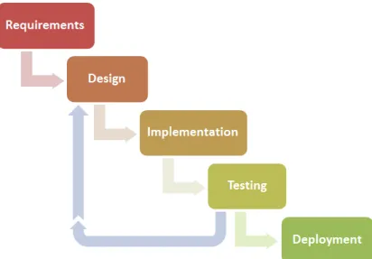
This definition and others may also be found on the online Microsoft Application Architecture Guide [15] along with other useful information regarding this matter. This project was developed within the context of a Masters dissertation and thus individually, in clear contrast with a full-blown corporate application. Therefore, due to its nature, most of the techniques for enterprise development were not adequate (e.g. group collaboration), so we opted for a downscaled and simplified model of Iterative and Incremental Development ( [16], [17]) that best fits the modest requirements of this work. Actually, our model could be even better described as an Iterative mini-Waterfalls [16] as shown in Figure 1.
Preparation for this work started with learning the fundamentals about light field image processing and computational photography (for a brief overview on the matter, see Chapter 3). It was followed by a brief study of the current existing tools and applications for light field processing of Lytro cameras. This enabled the
definition of Requirements, which included what type of application and which main features to develop.
Figure 1 – Overview of the software development methodology used: Iterative mini-Waterfalls.
We then initiated the iterative process of Design, Implementation and Testing, which started with a simple prototype developed under a Rapid Development method using the standard scripting language of Matlab and its default Graphical Interface architecture. This initial first stage was very important because it immediately underpinned some limitations of this development system.
Consequently a few critical decisions, such as changing to an Object Oriented Paradigm (OOP), were made sooner than if we had used the more “classic” non-iterative version of the Waterfalls model, which saved time, in the long run.
For details regarding the iterative part of the development process, see Chapter 5. After finishing the development, final testing and deployment were performed on Windows 7, 8 and 10, using the two latest versions of Matlab (R2015b and R2016a).
1.3.2. Dissertation
There are many ways to tell a story or explain an idea. The method used to present the Light Field Processor application, through this very document, is based on my own formal training on pedagogical techniques and professional experience as both a trainer and a teacher for many years.
The Association principle is a neuroscience theory that explains how the human brain learns through the association of ideas and lived experiences [18], [19]. Practice confirms that people learn more easily when they associate new knowledge with previous knowledge or with other experiences of the senses, which happen naturally when practicing the new knowledge.
Considering the wide diversity of expertise of our targeted group of users (as mentioned in Section 1.2.2 above) a Top-Down approach will be used, starting with less technical subjects, to reach a wider audience (Top), and then gradually progressing to the more technologically challenging information on the later chapters, oriented towards a more specialised group of people (Down).
By merging the Top-Down approach and the Association principle, it makes sense to start presenting the Light Field Processor application by its main features and how they can be reached through the graphical user interface; first in a broader way, then in practical terms.
As this process of learning unfolds, a user, whether a light field photographer, a multimedia student, a researcher on light field technologies or a software developer specialising in digital image processing, will gradually and effortlessly become aware of what a light field image is and how its data may be manipulated by experimenting the various outputs provided by the application.
If a reader of this work has some technical background on software engineering, or pursuits it, and wants to get a more technically oriented perspective regarding the development of the application, then it will be easier to understand the diagrams shown, as well as how and why some technical decisions were made and what was their purpose, when reading the subsequent chapters (in particular, Chapter 5).
1.3.3. This document’s readability
The elaboration of this document followed the rules of:
British English spelling;
The IEEE Editorial Style Manual for bibliographic sources, available at [20]. This document was produced with Microsoft Word 2010, which unfortunately does not include an updated template for the style rules imposed by IEEE in [20]. In order to comply with these rules and still have an automated mechanism of managing bibliographic sources within Microsoft Word, a new XSL template had to be developed. For that task we used BibWord [21] as a model. In the process we also took the opportunity to add some rules regarding online sources (that were not defined by IEEE) and create a consistent and hopefully more visually appealing formatting scheme.
Since this document will only be publicly distributed in static text formats (printed on paper or digital PDF file), there is no need to go into details on how to install the bibliography template.
1.4. Main Contributions of This Work
On a broader perspective, the main contribution of this work is obviously the development of the Light Field Processor computer application. However, such a project comprises different modules and features which require varied types of knowledge and skills. Therefore, dividing this global contribution into its constituent parts can certainly help in better understand its merits.
Nevertheless, in this introductory chapter we will do just an overview of some of those contributions. For details about them, see Chapter 4 and Chapter 5.
1.4.1. Application features perspective
Light Field Processor is a software application built to run on a Windows PC. It has a Graphical User Interface that aims to integrate its features into a whole functional unit, that:
Automates repetitive tasks;
Performs validation of data and inputs up to a certain level;
Provides interactive information;
Allows visualisation of a light field image in innovative ways (e.g. Viewpoint Navigator);
Does basic image processing (e.g. Colour Correction);
Adds an innovative way of systematically running and testing algorithms (e.g. Depth Filters engine);
Proposes the creation of a new file format (DLF) for storing decoded light field data;
Keeps user preferences and configuration options between different sessions.
1.4.2. Application development perspective
Matlab’s original purpose was essentially that of a powerful, practical and scalable calculator machine. Although currently it is much more than that, trying to develop a full graphical computer application with such a tool was certainly a very risky decision. Even more so when we consider that it was also developed using the new dot notation architecture (which only became available in Matlab R2014b) and was still unknown by most of its users during this work’s development. This notation is perhaps the most visible part of an attempt to construct a true Object Oriented Programming (OOP) paradigm, with classes and objects, in order to update Matlab’s development engine to modern techniques, standards and industry requirements.
It now seems obvious, after the development is finished, that building this application was only possible thanks to the use of OOP techniques which allowed the scalability and flexibility that such an application development required, especially in such a relatively short period of time.
As is often the case in scenarios like this, innovative solutions had to be developed to face the many yet unsolved problems faced with this new implementation. However, ultimately it was Matlab’s graphical interface engine that proved to be the most challenging for the developer. Details about this and other software developments will be discussed in Chapter 5.
1.5. Quick Overview of Contents
This dissertation is structured around three main parts (as explained in the methodology section):
1. Introduction to the work and its technologies (chapters 1-3); 2. Detailed presentation of the application (chapters 4-5);
3. Conclusions about the work: main contributions and suggestions for future work (chapter 6).
Part one is divided in three chapters: the first, and current chapter, does the formal introduction to this work; the second chapter goes through a brief history of photography because, amongst other reasons, knowing the past helps in predicting the future; the third chapter explains the most relevant concepts required to understand the remaining work.
The second part presents the software application from two different perspectives: (1) the user perspective or light field image researcher perspective, which encompasses the interface and all the application’s features; (2) the software developer perspective, which comprises aspects such as development methodologies used, application architecture and data structures implemented. Finally, the third part closes this work, including some of its major contributions and suggestions for future work.
C
H A P T E R
2
2.
H
OW
P
HOTOGRAPHY
W
AS
B
ORN
“And you, Divine sun, lend me your rays.” [Originally written in French, on a glass surface prepared with silver nitrate, this phrase actually shone when exposed to the sun!]
Hercule Florence, 1833
Humankind has gone a long way since the first forms of rock art, some dating back around 30000 years. Since then there has been a trend to make depictions ever more realistic.
On ancient civilisations, like the Greeks and the Egyptians, engravings in pottery and home walls reflected daily life on flat one-sided views.
Many centuries later, in the Western culture, the importance of images grew throughout the medieval period. First as a means to celebrate and “imprint” historic events in people’s minds (like the “Bayeux Tapestry” did for the conquest of England by the Normans [22]). Secondly, with the spread of religion, as a solution for the need to convey spiritual messages of things that people would otherwise only be able to imagine (e.g. demons). On a time when about 90% of the population in Europe was illiterate, images were much more efficient than words
to convey those ideas. This trend led to the wonderful works of art of the Renaissance and the importance of ever more realistic depictions.
2.1. The Birth of a New Technology
A word of caution is required before we start this brief journey into history. The evolution of photography had many contributors and sometimes simultaneous discoveries, some of them only recently became known. Therefore it is not easy to establish a definitive and clear chronological timeline of all great achievements. This brief study was conducted using several different sources, which are all shown. Although it may seem excessive, it is only a means to provide the tools so that a more inspective reader may confirm our findings. Having that into consideration we start by the beginning: how the term itself appeared.
2.1.1. The term
The word photograph had more than one independent author because it was a natural choice for anyone who knew Greek and had the knowledge about the technology. It is formed by the combination of the Greek words photo (light [23]) and grapho (to write, to draw up in writing [23], [24]) and it literally means “light drawing” or “drawing with light”.
Figure 2 – Hercule Florence, around the age of 70 [25].
Only relatively recently (1976) the world learned that the term was first used by a French-Brazilian painter and inventor, called Antoine Hercule Romuald Florence (Figure 2), who went to Brazil in 1824, with just 20 years of age. There he developed a technique to capture images which he used for the first time in 1832. We know that because he recorded it, in 1834, as “photographie” (French word for photography) in the set of notebooks he kept about his experiments (covered in Section 2.2) [26], [25], [27], [28], [29, p. 27].
John Herschel, an Englishman considered to be the first photo chemist [29, p. 79], made several contributions to the early development of photography and he used the terms photograph and photography in England, a few years later, in 1839, to describe both the product and the process [29, p. 27]. Curiously, because he was already a reputed scientist in the field, he is usually credited as being the one who coined the terms. Although he certainly did a lot to the establishment of those terms, the records of Antoine Florence provide proof that he, in fact, was the one who first used that term and should get proper credit for it.
2.1.2. How photography came into existence
By the XIX century, the optics required to produce photographic cameras already existed, but it was being used only for the production of telescopes because a method to capture a permanent image on a solid surface was not yet discovered. Around 1816, Joseph Nicéphore Niépce, a Frenchman who had been involved with etching and lithography, discovered a method to temporarily fix negative images on paper. Not satisfied with the results though, he continued experimenting with other materials and by 1822 he was able to permanently capture an image of an engraving of Pope Pius VII, in what is thought to be the first ever photographic image [30].
He called his technique heliography (Greek for “sun drawing”) and the plates in which the images were captured permanently he called heliographs. This process would serve as the conceptual model for the photoengraving industry. Using a camera obscura and applying his method, between 1826 and 1827 he produced the oldest surviving photograph of nature entitled “View from the Window at Le Gras”. A 1952 reproduction of that photograph is shown in Figure 3.
From the window of Niépce’s working room in Nice, photography would become a window to the World. For the discovery of this method Joseph Nicéphore Niépce is usually considered the inventor of photography [30], [29, pp. 27-28].
In 1826, Louis Daguerre, another inventor who was also pursuing a method to fix images obtained from light, contacted Niépce to propose a partnership. The two inventors started working towards a common goal in 1829, by improving on the heliograph, but Niépce died in 1833 leaving his method unpublished. His son, Isadore Niépce, would continue the work with Daguerre. Two years later, in 1835, Daguerre is credited to have discovered a method that shortened the exposure from hours to just around 20 minutes and still allowed an image to be stabilized, in what he called a daguerreotype [29, p. 28].
In September 1839 the French government announced the process to the world after agreeing to offer both inventors a pension for the technology behind it. The Daguerreotype became an instant success and lead to the birth of what we know today as the photographic industry [29, p. 28].
It is important to mention that there were other inventors who made important contributions to the development of photographic techniques. William Talbot, an Englishman, discovered a method to create engravings, although with an inferior quality to the Daguerreotype. However, in 1841 he developed a process, called
calotype, which yielded good quality and required only a fraction of the time
needed to produce a printed image on paper, but it was technically demanding and the license he imposed was very expensive, which confined its appeal only to the educated upper class, so it never became popular [29, pp. 28-30].
2.2. The First Photocopy Office
Another important pioneer in the development of photography was Hercule Florence, as mentioned earlier. The recorded details of his technique were confirmed to be valid, in 1976, by the Rochester Institute of Technology [31, p. 18].
Figure 4 – Photocopy of a Diploma made by H. Florence around 1839 [25].
His technique would yield superior results to the one developed later by Daguerre based on Niépce’s work, which would become the model worldwide. However, being isolated from the centre of technological development in Europe, his
discoveries went unknown outside of Brazil for more than a century [26], [25], [27], [28], [29, p. 27].
As an illustrator, painter and calligrapher, he was initially motivated by the need to reproduce his own documents as easily and as faithfully as possible. For that he created his own printing office, in the city of Campinas, Brazil, where he immediately started using his copying techniques commercially, as is shown by a photocopy of a diploma made by him around 1839 (Figure 4).
Since no other discovery of this kind is known earlier than this, it seems therefore fair to say that Florence was the first person to create a photocopy of a document and to use such technique commercially, which would constitute an industry in itself, in parallel with that of photography.
2.3. Adding Colour to Images
2.3.1. Maxwell: Validation of the trichromatic theory
The appearance of the theory of trichromatic colour vision [32, pp. 207-211] by Thomas Young in 1801 [33], which was further developed by Hermann von Helmholtz in 1850, motivated James Clerk Maxwell to prove it by using the branch of mathematics called Linear Algebra that had been recently developed. In his classic paper of 1855 [34], concerning experiments on colour, he demonstrated that a monochromatic light affecting three receptors should be able to be equally stimulated by a set of three different monochromatic lights.
He had a colour disc made especially to allow a visual demonstration of the results and conceived a colour triangle using his three primary colours (red, green and blue) which he claimed would allow anyone to determine, with mathematical precision, which amount of any of the primary colours was needed to synthesize a specific colour. It is important to notice though that colour triangles were already widely known after Tobias Mayer, a German astronomer and mapmaker [35], created one in 1758 to visually show the different gradients of colour that humans were able to distinguish.
Maxwell didn’t actually create a colour triangle, contrary to what some sources say [36]. He did however create a new method to use one with mathematical accuracy which was very important at a time when most theories derived from direct observation or experimentation and not by means of mathematical calculation. His principles would later be used to create colour spaces and laid the foundations for a new branch of science that researches the quantitative description of colour mixture and is used to quantify and describe human colour perception, nowadays known as colourimetry.
Figure 5 shows the original triangle envisioned by Maxwell and its modern implementation with real colours, including some example intensity values of the
three basic colours used to prepare the colour disc depicted to show that specific colour.
Figure 5 - Left: Colour triangle shown on Maxwell’s paper [34]. Right: A modern depiction of the colour triangle and colour disc envisioned by Maxwell using real colours [37].
In 1861, James Maxwell was invited to the Royal Institution in London to give a lecture on colour vision. By that time Thomas Sutton was perhaps the most prominent inventor in the field of photography in England, having created the first single lens reflex camera that very same year. It was therefore no surprise that Maxwell asked Sutton for help. The latter created three negatives of the same picture (a ribbon) but through three colour filters: red, green and blue. These were then used to create lantern slides which Maxwell used to make a projection of the images, as shown in Figure 6.
When the first slide was projected the image was seen on red, but when all three monochromatic images were projected overlapped at the same spot, a colour image of the ribbon was seen. Although by modern standards the virtual image certainly lacked in the spectrum of “reds” and “greens” (we now know that the materials used were not sensitive to red light and were only marginally sensitive to green), the projection was convincing enough for a XIX century audience unprepared to evaluate something that had never been attempted before.
Figure 6 – Depiction of three colour filtered plates that allowed the reproduction of a colour image for the first time, using the trichromatic process (adapted from [38]).
Camera Obscura
In 1020 AD, Ibn al-Haytham, an Arab physicist, published a Book of Optics in which he described a pinhole camera and a camera obscura.
Some sources, like Wikipedia [39] and BBC (in both news [40] and video documentary [36]), affirm that this is the first photograph ever taken. Perhaps some caution before making such a bold statement would have helped understand that what was captured were three independent monochromatic photographs of the same subject (a colour ribbon) that were later projected overlapped at the same spot on a wall or blackboard. No single plate captured all the colours, and so no permanent colour image was captured with this
process, and therefore such a statement cannot be considered to be true. Moreover, if some sort of image projection were to be considered a photograph then one might as well consider any projection of a camera obscura, invented around 1000 years ago, to be a colour photograph too.
2.3.2. Hauron: First implementation of the three-colour method
In 1868 Louis Ducos du Hauron patented a process that allowed three-colour prints on paper using the subtractive method, which instead of adding intensities of red, green and blue colours to black (additive colour system), subtracts their respective opposite colours: cyan, magenta and yellow, from white. For a detailed explanation of colour systems please consult [41] at The American WideScreen Museum Web site.
The “negatives” he developed used materials that were a bit more sensitive to the red and green spectrums of light than the ones used by Maxwell and Sutton seven years before, but were still incapable of capturing a satisfyingly range of intensities of these colours and it also required long exposure times.
Although this technology was far from yielding the best results, to the best of my knowledge, it was the first to produce a true colour printed photograph (not just a projected combination of three monochromatic images, as was the case of the Maxwell/Sutton solution). In Figure 7 the three coloured layers are clearly visible.
Figure 8 – Colour photograph from the 1890s using the interference method [44].
2.3.3. Lippmann: A different approach to colour
Gabriel Lippmann was a physicist and inventor who played a fundamental role in the development of light field photography. But before that, he would become worldwide known for proposing a method to solve the problem of colour photography that was completely different from the previous ones.
Around 1886 he started searching for a method of fixing colour on a photographic plate and by 1891 he announced a solution by using a phenomenon called interference which physics explains as the outcome of the collision and resulting interference of two waves and applies to almost any kind of wave, be it radio, light or surface water.
In 1892 he produced the first photographs using his method: one is shown in Figure 8. This invention would later earn him the Nobel Prize in Physics for 1908. His Nobel lecture is available online and explains the details of the process [42], [43], [44].
However the search for the ideal colour method did not end here because the interference process was too complex, had problems with reflections of waves and required the use of mercury which is highly toxic, so it was never adopted by the industry [45], [39].
2.3.4. Ives: Avoiding printed paper
Although Maxwell proved the trichromatic theory to be valid and useful for the purpose of showing colour images, the photographic emulsions were only sensitive to ultraviolet, violet and blue wavelengths, which only allowed what were essentially monochromatic images. Therefore, further development in colour photography required a development in chemistry and that took many years of new experiments and improvements.
Meanwhile, a way to avoid this problem was to not use paper to print the images. Frederic Eugene Ives, a North American photography pioneer, did just that with his “Kromskop” system which was commercially available in England in late 1897 [45].
Using the previous work of Maxwell, he created a system in which three black and white “positive” images were taken through special red, green and blue filters. Then, instead of printing those images on paper, they were printed on transparencies (called Kromograms — an example is shown in Figure 9) which would then be viewed on a specific device with special colour filters: the
between a microscope and a slide projector. There were monocular and stereoscopic versions, the latter being the most popular for allowing visualisations in full colour and 3D, through its pair of lenses, which at the time certainly must have stunned viewers.
Figure 9 – Vase of Flowers: A Kromogram of 1897 [46].
Although it delivered very good results, the fact that it required special equipment and three pictures to be made of each object with extreme accuracy made it unattractive for most people and it was not a commercial success being discontinued a decade later [45], [46].
2.3.5. And the winners are: the Leopold musicians!
In 1903, in France, the famous Lumière brothers patented the Autochrome which would become the major colour photographic process after it was commercially available in 1907. It was an additive colour process which used a glass plate coated with tiny grains of potato starch of red-orange, green and blue-violet colours that served as filters [47].
Nevertheless, the true hero of the colour processes arrived in the 1920s, through the unexpected discoveries of two American musicians: Leopold Godowsky Jr. and Leopold Mannes. They started experimenting with colour in 1917 after watching a movie that was supposed to be in colour but failed their expectations. They refined their process during the 1920s with the backing of an investor.
In 1930 the system impressed Eastman Kodak so much that both men were hired to work in the Eastman Kodak laboratories. The outcome was launched in 1935. Named Kodachrome, being commercially viable and backed by the marketing power of a company like Kodak, it would become the base for all further developments in this field.
As seen in Figure 10, the Kodachrome yielded very good quality colours thanks to a subtractive colour film coated with three layers each of them only sensitive to one third of the visible colour spectrum, usually represented by the colours: red, green and blue. Other chemical processes were required to extract the final slides, but Kodak made it simple for their target home cinema users, by simply allowing them to send in their negatives and Kodak would send them back the slides already processed. This greatly helped the system become a success commercially.
Figure 10 – A Kodachrome picture by Chalmers Butterfield [45].
Further developments followed. An important one was done the next year by Agfa, which found a way to develop the three colour layers at the same time and thus greatly simplify the process.
In 1942 Kodak launched the Kodacolor which was a negative film used specifically for still photography and allowed colour prints on paper. Together, these processes were adopted by the cinema and photography industries as a standard until the appearance of digital cameras in the 1990s [39], [45], [48], [49].
2.4. The Modern Era
Knowing about the past helps anyone to better preview the future, which is something important for fast-paced technological areas like digital photography and imaging. We think that task is already accomplished with what was mentioned so far in this chapter, and it is out of the scope of this work to proceed on further historical details.
However, some technologies that relate more closely to the ones used in this work, although much more recent, still need a few more words.
2.4.1. Developments leading to light field photography
Although not important for printed photography, stereoscopy played an important role in photography and image in the XIX century. The stereoscope was invented in 1838 by Charles Wheatstone and remained hugely popular throughout the century.
In 1846, Michael Faraday, a brilliant English experimentalist, was the first to propose that light should be interpreted as a field, just like magnetic fields on which he had been working for many years.
In 1908, Gabriel Lippmann introduced what he then called “integral photography”, to describe a plane array of closely spaced small lenses that is used to capture a scene, from several slightly different perspectives (horizontal and vertical). This principle was the basis to develop what is now known as light field photography, the key technology upon which this work was built.
2.4.2. Current light field cameras
Light field photography (sometimes also known as plenoptic photography) only became a reality thanks to the digital revolution and the integration of many of the previous major inventions such as colour, stereoscopy and autofocus. This was a principle that guided this work as well: integration.
It even expands technologies from stereoscopy (two views) to multiscopy (multiple views) and pre-single-focus, meaning one single focus chosen at the time of capture, to post-multi-focus, meaning selection of one single focus with control over depth of field or all-in-focus, after capture. See Chapter 3 for definitions on some of these concepts.
Light field photography is not new as a concept, as mentioned above, but only relatively recently has been made a reality by companies like Raytrix (Germany) and Lytro (USA).
On July 2010 Raytrix launched its first models R5 and R11 geared towards the industrial and scientific markets [50], with effective resolutions of up to 1 and 3 megapixels respectively.
On October 2011 Lytro launched its first generation light field camera called F1, oriented towards the consumer market, with an effective resolution of roughly 1.1 megapixels [51].
In 2014, Lytro upgraded its cameras range to the second generation with the Lytro Illum, which served as reference to this work [10]. The camera offers a 40-megaray light field sensor, 8x optical zoom range and a constant f/2.0 aperture. For more technical details about this camera, see [52].
C
H A P T E R
3
3.
L
IGHT
F
IELD
I
MAGING
C
ONCEPTS
If we present a painting, we speak of Art. If we present technology, we speak of Science. Why should we then say “State of the Art” to present the current development status of Technology or Science?
My enquiring mind
The target audience of this work is constituted mainly by students and researchers interested in light field photography and related technologies, which may encompass a wide range of areas of expertise, as stated before. So it seemed wiser to use a language that would be understandable by a wider audience and not just by scientists of the field. Besides that, some concepts require previous knowledge of other concepts.
In order not to make this a step by step mechanical reading experience, the approach used in this work is to first introduce the concepts in a more general way, and then, gradually, go into more technical details, as needed.
The concepts explained here are not supposed to be an exhaustive review of the technology but rather a practical and oriented overview geared towards providing a better understanding of the computer application developed within this work. To those who want to deepen their knowledge, several sources are provided.
3.1. Human Vision
3.1.1. Binocular vision
Some animals, in particular humans, are equipped with a pair of frontal eyes which are aligned horizontally. That configuration allows the eyes to capture images from two slightly different viewing angles simultaneously. The great advantage of having two such images is allowing stereopsis, which is a very powerful process of depth perception. These are the defining features of binocular vision [32, pp. 44-51], [53].
3.1.2. Stereoscopy
Stereoscopy is a technique used to simulate the effects of binocular vision, especially depth perception, in man made products.
A stereoscopic method or system requires that two images, with slightly different horizontal perspectives, be presented to the eyes simultaneously (or almost) in a convincingly manner so that the Human Visual System (HVS) uses them, instead of the real world, in the stereopsis process from which depth is perceived [54].
3.1.3. Binocular disparity and stereopsis
Binocular Disparity explores the differences in geometry obtained from binocular
vision. Since human eyes are levelled on the same horizontal plane they only provide horizontal disparity. Therefore, in the context of human vision, Disparity usually relates only to horizontal distances, although the concept itself can be equally applied to both vertical and horizontal distances, so it is a good practice to explicitly mention the direction of disparity [55], [56], [53].
Figure 11 – Effects of horizontal disparity on binocular vision (original creation from parts of [4]).
In Figure 11 we can see the effects of horizontal disparity in binocular vision. Notice the slight shift of the apple, relative to the orange behind it, in the three depictions. This happens because the apple is nearer than the orange. Since depth is inversely proportional to disparity (i.e. the closer an object is to the camera or the eye, the greater the disparity is) [57] it may be used to determine the depth of objects in a scene [8], [58]. This is the underlying principle of stereopsis.
Figure 12 – Light rays reflected off an apple [4].
In the context of photography, Disparity may be understood as the distance between a specific point of the world, represented in two images of the same scene but taken from different perspectives.
3.1.4. Sensing light
Each eye behaves much like a visual sensor by collecting rays of light from one single direction, which is controlled by the movement of the head and the eyeball. More detailed data is collected on the retina of the eye coming from a specific spot of the world where the image is focused with the help of the lens.
Although the dynamic range of wavelengths of light is, in practice, virtually unlimited, the resources of any biological system, such as the HVS, are not. So, in order to make the process of interpreting light more “manageable” and possible to occur in real time, the HVS processes only a narrow band of the full light spectrum, between about 400nm to 700nm, which is commonly known as the spectrum of visible light [32, pp. 44-51], [59, p. 5].
3.1.5. Interpreting light
We live in a world of light. The sun is our major source of natural light during daytime and in its absence we may use artificial light, like that produced by a lamp. One fact that may not appear immediately obvious though, is that most of the light rays processed by our eyes do not come directly from its source (be it natural or artificial); instead, they come from some sort of reflection on other objects and structures of the world around us. This constant process of bouncing off other surfaces makes the light rays lose energy until they become so faint that we cannot perceive them.
To interpret the apple of Figure 12, the eyes capture all the rays that are reflected from the apple in their direction and process those with enough energy to be detected by their retinas. Since we have binocular vision, our brain gets two images of the apple from two slightly different perspectives (as shown in Figure 11) and, mainly through stereopsis, it is able to infer depth and therefore we are able to perceive the apple in 3D space with its appearance [4], [8, pp. 6-8], [32, pp. 44-51].
Figure 13 – Parameterization of the 5D Plenoptic function [62].
3.2. Light Field Theory Overview
3.2.1. The plenoptic function
An image is formed from the light rays that hit the capturing device sensor. If we were to fully reconstruct, in space-time, the scene represented by that image from those light rays, we would need to store seven parameters for each light ray, relating to time, frequency (or wavelength), space and direction.
These parameters were formally described by Adelson and Bergen, in 1991, through what they called the Plenoptic function [60], which was an improvement on the work done by the Russian physicist Andrey A. Gershun, in 1936, regarding light fields [61].
The Plenoptic function has been used as a modelling function in computer graphics related fields to express the image of a scene, viewed from any possible position and angle, at any moment in time; or, paraphrasing Carl Sagan, as a description to the omnipresent image of everything that ever existed or will ever exist, on a specific scene. It serves as the basis for much of the light field imaging theory and for that reason a more detailed explanation of its parameters follows.
3.2.1.1. Time
In a metaphorical language, one could say that a photograph is like a moment frozen in time. The literal meaning of this sentence is not far from reality though, because each picture is truly unique! Even if we retake that picture, it will be done in a different moment in time and therefore it will use different light rays, even though their properties might be very similar to the ones captured originally. Nevertheless, since time does not vary in a photograph it is not important for our present work and will consequently be ignored, for the sake of simplicity.
3.2.1.2. Wavelength
In the process of image formation, this is the value that will later be translated into the colour that we see on every picture element.
Wavelength (λ) is measured in nanometres (nm). Since Frequency (f) is inversely proportional to wavelength, it may also be used to
describe this property of light.
3.2.1.3. Space and Direction
To complete the representation of a light ray we need to know a point in space where the ray passes, as well as its direction. The former requires three parameters, usually x, y and z, whilst the latter needs two angles, commonly represented by the Greek letters θ and φ. If we restrict the Plenoptic
Figure 14 – A light field represents the amount of energy across a tubular
area [62].
function to these five geometric parameters, it then becomes a 5D function that expresses the flow of light in 3D space and can be represented as seen in Figure 13 [58], [62], [60].
3.2.2. Radiance
For this work, perhaps the most important aspect to comprehend about Radiance (L), along a light ray, is that it may be understood as the amount of energy given by light particles (photons) flowing through all possible straight lines in a constrained tubular area.
This work does not require any formal measurement of radiance because that is done
by the optics and electronics systems of any light field camera. Yet, this is an important concept to grasp since it is the final “piece of the puzzle” in the process of understanding what a light field really is, and for the sake of completeness it should be noticed that Radiance is measured in watts (W) per steradian (sr) per meter squared (m2). The two variables that define the actual tubular area in which
light is measured are the steradian, which measures a solid angle, and the meter squared, which measures the cross-sectional area, as Figure 14 visually expresses [62], [58].
3.2.3. Light field
Considering the information conveyed in the previous sections and using a more formal approach, it is now possible to affirm that a Light Field represents the total amount of energy (radiance) moving in all directions (to which we called light rays), throughout all points in space, in a given area [58], [62], [4], [63].
3.3. Light Field Image Formation
3.3.1. Brief overview of a light field camera
It is out of the scope of this work to discuss technical details about the optics or the electronics systems of a light field camera. However, learning a few things about those may help in better understanding certain concepts that are important for this work, so a brief overview follows.
3.3.1.1. Microlens Array
A conventional 2D camera captures light with the lens and sends it directly to the sensor where the image is formed, as shown on the left side of Figure 15. However, a light field camera has an intermediary between both: the Microlens Array (also written as Micro Lens Array and abbreviated as MLA).
![Figure 5 - Left: Colour triangle shown on Maxwell’s paper [34]. Right: A modern depiction of the colour triangle and colour disc envisioned by Maxwell using real colours [37]](https://thumb-eu.123doks.com/thumbv2/123dok_br/19174247.942497/30.892.145.705.184.465/figure-colour-triangle-maxwell-depiction-triangle-envisioned-maxwell.webp)
![Figure 7 – An 1877 photograph using Hauron’s method [39].](https://thumb-eu.123doks.com/thumbv2/123dok_br/19174247.942497/31.892.283.652.853.1112/figure-photograph-using-hauron-s-method.webp)
![Figure 9 – Vase of Flowers: A Kromogram of 1897 [46].](https://thumb-eu.123doks.com/thumbv2/123dok_br/19174247.942497/33.892.291.638.221.528/figure-vase-of-flowers-a-kromogram-of.webp)
![Figure 10 – A Kodachrome picture by Chalmers Butterfield [45].](https://thumb-eu.123doks.com/thumbv2/123dok_br/19174247.942497/34.892.121.728.289.653/figure-kodachrome-picture-by-chalmers-butterfield.webp)
![Figure 11 – Effects of horizontal disparity on binocular vision (original creation from parts of [4])](https://thumb-eu.123doks.com/thumbv2/123dok_br/19174247.942497/38.892.146.705.749.922/figure-effects-horizontal-disparity-binocular-vision-original-creation.webp)