Gonçalo Nuno Afonso Azevedo
Licenciado em Ciências da EngenhariaElectrotécnica e de Computadores
Wireless Triple Play System
Dissertação para obtenção do Grau de Mestre em Engenharia Electrotécnica e Computadores
Orientador :
Prof. Doutor Luís Bernardo, Professor Auxiliar
com Agregação, FCT-UNL
Co-orientador :
Engenheiro Tiago Duarte, Partner, Softconcept
Júri:
Presidente: Prof. Doutor Pedro Amaral
iii
Wireless Triple Play System
Copyright cGonçalo Nuno Afonso Azevedo, Faculdade de Ciências e Tecnologia, Uni-versidade Nova de Lisboa
Acknowledgements
I would like to acknowledge several people that helped me through the development and writing of my thesis.
First I would like to show my gratitude towards both my supervisors Prof. Luís Bernardo and Eng. Tiago Duarte for their insightful guidance and support when it was most needed.
I would like to thank Nuno Malaguerra and Maurice Dini from Meru Networks for bor-rowing the testing equipments and for their endless availability during the development of my dissertation.
Bruno Lima from 2007com was a valuable help during the development of my thesis. I would like to thank him for his knowledge and method as also with the exemption of the Alcatel-Lucent testing equipments.
I would like to thank Tim June and Chunlei Yi from OpenVox for their value help during the development of my thesis. Their great knowledge on installation and configuration process of SIP interfaces were a great help for the developing of this work.
Eng. Hugo Azevedo for its constant guiding, patience and companionship throughout my dissertation. I would like to thank him for his thorough knowledge and method, otherwise I would not accomplish this lengthy milestone.
Duarte, Marcelo Rodrigues, José Manuel, Fabio Oliveira, Bruno Caixinha, Pedro Antunes and to Filipa Pacheco for all of comprehension, support and encouragement that she al-ways transmitted me.
Finally, I would like to show the most kind and special gratitude to my family: my Mother and Father. They have always supported me during the most difficult times of my life.
A special thanks to Softconcept and all of their collaborators by the technical, financial and logistic support through the development of this project.
To all of you, thank you!
Almada, February2014
Abstract
Triple play is a service that combines three types of services: voice, data and multimedia over a single communication channel for a price that is less than the total price of the individual services. However there is no standard for provisioning the Triple play ser-vices, rather they are provisioned individually, since the requirements are quite different for each service. The digital revolution helped to create and deliver a high quality media solutions. One of the most demanding services is the Video on Demand (VoD). This im-plicates a dedicated streaming channel for each user in order to provide normal media player commands (as pause, fast forward).
Most of the multimedia companies that develops personalized products does not always fulfil the users needs and are far from being cheap solutions. The goal of the project was to create a reliable and scalable triple play solution that works via Wireless Local Area Network (WLAN), fully capable of dealing with the existing state of the art multimedia technologies only resorting to open-source tools.
This project was design to be a transparent web environment using only web technolo-gies to maximize the potential of the services. HyperText Markup Language (HTML), Cascading Style Sheets (CSS) and JavaScript were the used technologies for the develop-ment of the applications. Both a administration and user interfaces were developed to fully manage all video contents and properly view it in a rich and appealing application, providing the proof of concept.
The developed prototype was tested in a WLAN with up to four clients and the Quality of Service (QoS) and Quality of Experience (QoE) was measured for several combinations of active services. In the end it is possible to acknowledge that the developed prototype was capable of dealing with all the problems of WLAN technologies and successfully delivery all the proposed services with high QoE.
Resumo
Triple play é um serviço que combina diferentes tipos de serviços: voz, dados e multimé-dia num único canal de comunicação, por um valor monetário inferior ao total de cada um dos serviços. No entanto, não existe nenhum protocolo que defina na totalidade os serviços de Triple play, devido às diferenças de requisitos de cada um dos serviços. Cada um dos serviços tem que ser distribuído individualmente. A evolução digital ajudou na criação de várias soluções multimédia de alta qualidade. Uma das mais promissoras é o VoD, que implica um canal dedicado para cada utilizador, de forma a possibilitar comandos de utilização normais como, por exemplo, a pausa ou o avançar rápido. As empresas oferecem produtos personalizados que nem sempre viabilizam todas as ca-pacidades e necessidades que os clientes procuram. Estas ofertas estão longe de serem soluções viáveis ao nível monetário. O objectivo desta dissertação foi criar um sistema Triple play escalável e fidedigno, com capacidade de operar através de redes sem fios. Este sistema deve ser capaz de funcionar com o atual estado da arte das tecnologias mul-timédia e com recurso apenas a sistemas de código aberto.
Este projeto foi desenhado para ser um ambiente transparente e utilizar apenas tecnolo-gias web de forma a maximizar o potencial dos serviços Triple play. Foram utilizadas tecnologias como o HTML, CSS e o JavaScript para o desenvolvimento das aplicações. Mostrou-se necessária a criação de uma interface de administração, bem como uma inter-face para o utilizador, de forma a possibilitar a manutenção dos conteúdos de multimédia e visualizá-los num ambiente apelativo para o utilizador.
O protótipo desenvolvido foi testado numa rede sem fios com até quatro clientes e a qualidade de serviço e a qualidade de experiência dos clientes foram medidas para vá-rias combinações de serviços ativos. Em conclusão, foi possível verificar que o protótipo desenvolvido, ainda que longe de ser uma solução profissional, se apresentou capaz de lidar com todos os problemas das redes sem fios e fornecer todos os serviços propostos com elevada qualidade de experiência.
Contents
1 Introduction 1
1.1 Thesis focus and scope . . . 1
1.2 Problem statement and goals of the research . . . 1
1.3 Dissertation’s Structure . . . 3
2 Background and Related work 5 2.1 Network standards for multimedia . . . 6
Transport layer protocols . . . 7
Application layer protocols . . . 8
2.2 Multimedia services . . . 12
Video . . . 13
Voice . . . 24
2.3 Quality measurement . . . 27
User experience . . . 27
Multimedia services . . . 29
Standards and models for video quality assessment . . . 31
3 Triple-play Model 41 3.1 Introduction . . . 41
3.2 System Model . . . 41
3.3 Triple-play architecture . . . 42
3.4 Architecture module specification . . . 44
IPTV . . . 44
VoD . . . 49
Open source software streaming solutions . . . 53
VoIP . . . 54
4 Implementation 61
4.1 Introduction . . . 61
4.2 Development stages . . . 61
4.3 Solution requirements . . . 62
4.4 Client . . . 63
Requirements . . . 63
Set-top box prototype . . . 64
User interface . . . 68
4.5 Multimedia Server . . . 74
IPTV . . . 75
VoD . . . 81
VoIP . . . 84
4.6 Solution limitations . . . 85
5 Experimental results and discussion 89 5.1 Introduction . . . 89
5.2 Environment and testing methodology . . . 89
Equipments . . . 90
Used tools . . . 92
Configuration . . . 93
Testing scenarios . . . 95
5.3 Testing results . . . 97
Network Metrics . . . 98
PSNR Metric . . . 103
MSE Metric . . . 105
VQM Metric . . . 108
6 Conclusions and Future Work 111 6.1 Conclusions . . . 111
6.2 Future Work . . . 112
A Appendix 127 A.1 Video coding standards . . . 127
MPEG-2 . . . 129
MPEG-4 . . . 131
H.264/AVC . . . 132
A.2 H.323 . . . 133
CONTENTS xv
C Appendix 139
C.1 LIRC . . . 139
C.2 User interface . . . 147
C.3 VLC plugin . . . 147
C.4 Remote Navigation . . . 149
C.5 IPTV module application . . . 151
C.6 VoD module interfaces . . . 153
C.7 VoD module application . . . 153
C.8 Asterisk installation and configuration . . . 153
Asterisk . . . 153
PHP . . . 156
Apache . . . 157
FreePBX . . . 157
C.9 FreePBX interface . . . 161
C.10 Asterisk files . . . 162
D Appendix 167 D.1 Testing results . . . 168
Scenario 1 . . . 168
Scenario 2 . . . 173
List of Acronyms
3GPP 3rd Generation Partnership Project
ACL Access Control List
ADC Analogue to Digital Converter
AGC Automatic Gain Controller
AP Access Points
API Application Programming Interface
ARM Adaptive Radio Management
ATIS Alliance for Telecommunications Industry Solutions
AVC Advanced Video Coding
CA Conditional Access
CAT Conditional Access Table
COFDM Coded Orthogonal Frequency Division Multiplexing
CP Cyclic Prefix
CSCF Call Session Control Function
CSS Cascading Style Sheets
DAHDI Digium Asterisk Hardware Driver Interface
DB Data Base
DCCP Datagram Congestion Control Protocol
DE-MUX Demultiplexer
DHCP Dynamic Host Configuration Protocol
DMO Dynamic Multicast Optimization
DNS Domain Name System
DRM Digital Rights Management
DVB Digital Video Broadcasting
DVB-T Digital Video Broadcasting - Terrestrial
EPG Electronic Program Guide
ES Elementary Streams
ETSI European Telecommunications Standards Institute
FEC Forward Error Correction
FFT Fast Fourier Transform
fps Frames Per Second
FR Full-Reference
FXO Foreign Exchange Office
FXS Foreign Exchange Station
GI Guard Interval
GNOME GNU Network Object Model Environment
GOP Group Of Pictures
GPL General Public License
GUI Graphical User Interface
HDTV High-Definition Television
HTB Hierarchical Token Bucket
HTML HyperText Markup Language
HTTP Hypertext Transfer Protocol
HVS Human Visual System
xix
IASF IPTV Application Service Functions
ICT Information and Communication Technologies
IETF Internet Engineering Task Force IF Intermediate Frequency
IGMP Internet Group Management Protocol
IIF IPTV Interoperability Forum IMS IP Multimedia Subsystem
IP Internet Protocol
IPTV Internet Protocol Television IR Infrared
ITF IPTV Terminal Functions
ITU International Telecommunications Union
ITU-R International Telecommunications Union Radiocommunication Standardization
Sector
ITU-T International Telecommunications Union Telecommunications Standardization
Sec-tor
IVR Iteractive Voice Response
LIRC Linux Infrared Remote Control MC Multipoint Controller
MCE Media Center Edition
MCF Media Control Functions MCU Multipoint Control Units
MDF Media Delivery Functions
MGCP Media Gateway Control Protocol MOS Mean Option Score
MP Multipoint Processors
MPEG Motion Pictures Experts Group
MPL Mozilla Public Licensing
MRO Multicast Rate Optimization
MSE Mean Square Error
MUX Multiplexer
NAFC Network Attachment Control Functions
NAL Network Abstraction Layer
NASS Network Attachment Subsystem
NGN Next Generation Network
NIT Network Information Table
NPAPI Netscape Plugin Application Programming Interface
NR No-Reference
OFDM Orthogonal Frequency Division Multiplexing
OIF Open IPTV Forum
OS Operation System
PAT Program Association Table
PBX Private Branch Exchange
PES Packetized Elementary Streams
PESQ Perceptual Evaluation of Speech Quality
PHP PHP Hypertext Preprocessor
PID Packet Identifier
PMT Program Map Table
POE Power over Ethernet
PSI Program Specific Information
PSNR Peak-to-peak Signal-to-Noise Ratio
PSTN Public Switched Telephone Networks
QoE Quality of Experience
xxi
RACF Resource and Admission Control Functions
RACS Resource and Admission Control Subsystem
RF Radio Frequency
RMS Root Mean Square
RR Reduced-Reference
RTP Real-Time Transport Protocol
RTCP Real-Time Control Protocol
RTMP Real-Time Messaging Protocol
RTSP Real-Time Streaming Protocol
SCF Service Control Functions
SCCP Skinny Call Control Protocol
SCTP Stream Control Transmission Protocol
SDF Service Discovery Function
SDK Software Development Kit
SDP Session Description Protocol
SE Standard Edition
SER SIP Express Router
SIP Session Initiation Protocol
SSF Service Selection Function
SSH Secure Shell
STB Set-Top Box
TCP Transmission Control Protocol
TIF Transport Information Filter
TISPAN Telecommunications and Internet converged Services and Protocols for
Ad-vanced Networking
TOS Type of Service
TTY Teletype write
TV Television
UAC User Agent Client
UAS User Agent Server
UE User Equipment
UDP User Datagram Protocol
URI Uniform Resource Identifier
USB Universal Serial Bus
VCL Video Coding Layer
VLAN Virtual LAN
VLM VideoLAN Manager
VoD Video on Demand
VoIP Voice over Internet Protocol
VQM Video Quality Metric
VQEG Video Quality Experts Group
WLAN Wireless Local Area Network
List of Figures
2.1 Video transmission over an IP network (based on [88]). . . 6 2.2 RTSP Message flow example. . . 10 2.3 SIP Message flow example. . . 11 2.4 IPTV domain model [93]. . . 19 2.5 ITU-T NGN-IMS-based IPTV Architecture [73]. . . 21 2.6 TISPAN NGN-IMS-based IPTV Architecture [16]. . . 23 2.7 Generalized model of VoIP architecture [104] . . . 25 2.8 QoE relationship with QoS [1]. . . 30 2.9 Classification of media-layer objective and subjective video quality models
[49]. . . 32 2.10 Reduced Reference method. . . 36 2.11 No Reference method. . . 37 2.12 Full Reference method. . . 37
3.8 SIP register message flow client-server. . . 57 3.9 SIP session establishment message flow client-server. . . 58
4.1 Developing stages of the implementation process. . . 62 4.2 User interface components. . . 69 4.3 IPTV and VoD user interface block architecture. . . 71 4.4 VoIP user interface block architecture. . . 73 4.5 Multimedia server components. . . 75 4.6 IPTV Java application. . . 79 4.7 Design of the DB where the channels info are stored. . . 80 4.8 Class diagram of Java application. . . 80 4.9 Conceptual diagram of the IPTV working process. . . 81 4.10 Design of the DB table where the video information is stored. . . 83 4.11 Conceptual diagram of the VOD working process. . . 83
5.1 Testing scenario used. . . 90 5.2 Video sample conversion diagram. . . 97 5.3 Video sample conversion codec data. . . 97 5.4 Network usage in scenario 1 from the multimedia server. . . 100 5.5 Network usage in scenario 2 from the multimedia server. . . 100 5.6 Network usage in scenario 3 from the multimedia server. . . 103 5.7 PSNR Metric for 100Kbps of DATA traffic in scenario 1. . . 104 5.8 Frame comparison with N=2 clients in PSNR Metric for 100Kbps of DATA
traffic in scenario 1. . . 104 5.9 Frame comparison with N=4 clients in PSNR Metric for 1000Kbps of DATA
LIST OF FIGURES xxv
5.16 VQM Metric for 100Kbps of DATA traffic in scenario 2. . . 108 5.17 VQM Metric for 100Kbps of DATA traffic in scenario 3. . . 109
A.1 GOP structure and dependencies between I,P and B frames [46]. . . 128 A.2 Evolution of video coding standards [29]. . . 129 A.3 MPEG-2 transport stream structure with PSI table sequence (Based on [3]). 130 A.4 Construction and encapsulation of MPEG-2 TS by RTP (Based on [88]). . . 131 A.5 Construction and encapsulation of MPEG-4 by RTP (Based on [88]). . . 132 A.6 Difference in compression rates between MPEG2 and H264 [4]. . . 133 A.7 H.323 network architecture [95]. . . 134
B.1 Functional DVB-T receiver block diagram . . . 135
C.1 User interface - IPTV. . . 147 C.2 User interface - VoD. . . 147 C.3 User interface - thumbnail selection. . . 148 C.4 User interface - movie description. . . 148 C.5 User interface - VoIP. . . 149 C.6 User interface - VoIP client. . . 150 C.7 IPTV java application - list of channels tab . . . 151 C.8 IPTV java application - channels.cfg selection . . . 151 C.9 IPTV java application - Log console selected . . . 152 C.10 VLM - Telnet interface . . . 153 C.11 VLM - HTTP interface . . . 154 C.12 VOD java application - vod_config.vlm selection . . . 154 C.13 IPTV java application - Log console . . . 155 C.14 FreePBX interface - home page . . . 161 C.15 FreePBX interface - extensions . . . 161
List of Tables
2.1 A comparison of IPTV and Internet TV services. . . 14 2.2 IPTV Standardization overview [62]. . . 17 2.3 SIP and H.323 components [85]. . . 25 2.4 Protocols used by H.323 and SIP [85]. . . 25 2.5 Impairments to video and audio services (Based on [88]). . . 31 2.6 Quality and Impairment scale with MOS conversion [88]. . . 33 2.7 MOS scale for the comparison between samples [88]. . . 33 2.8 Categories of objective quality assessment models (Based on [111]). . . 35 2.9 ITU-T Recommendations for objective assessment methods. . . 35 2.10 Mapping of MOS and VQM [88]. . . 39
5.1 Testing scenarios parameters. . . 96 5.2 Network metrics for 100Kbps of data traffic in scenario 1. The channel
capacity measures the AP’s estimation for the total datarate available, the utilization measures the channel utilization. . . 99 5.3 Network metrics for 100Kbps of data traffic in scenario 2. . . 101 5.4 Network metrics for 100Kbps of data traffic in scenario 3. . . 102
1
Introduction
1.1
Thesis focus and scope
The main propose of this thesis is to study the feasibility of using Wireless Local Area Net-work (WLAN) technology to deliver an integrated web based triple-play solution (video, voice and data), which has high Quality of Service (QoS) and Quality of Experience (QoE) requirements.
The work comprises the study of video coding and transmission, QoS mechanisms for wireless networks and assessment of methodologies to be used for the implementation of the system model. It includes the implementation of a full architecture including the client and the servers. It also includes the assessment of the QoE and QoS achieved. It was early decided that all the system would be implemented using adequate existing open-source resources, and the other necessary applications would be developed.
1.2
Problem statement and goals of the research
this enormous increase triple-play services started to appear. Triple-play means to merge radio transmission, communications transmission and computer transmission in the in-formation transmission. It does not mean the telecommunication network, computer network and cable television network will be converged in a physical way, but it refers to the integration of high-level business application. Triple-play service is a concept that means delivering video, voice and data through a single broadband connection, in this case WLAN. However, there is no standard for provisioning the triple-play services. Rather they are provisioned individually, since the requirements are quite different for each of the services. Such integration of network, communications and broadcasting technology gathers a variety of media onto a single platform and thus it will change the way the system actually works. Within the development of multimedia applications, the main problem faced by triple-play is the integration between the telecommunication net-work, which functions as the promotion of information transmission channel, and radio and television network, which possesses the advantages of disseminating information. Triple-play puts an end to the times when radio and television network monopolized information transmission while telecommunications monopolized the broadband opera-tion [89].
Another challenge are the WLAN characteristics. WLAN are more sensitive to interfer-ence and therefore more lossy and unreliable. Indeed, it is a challenging task to provide a guaranteed level of QoS for real-time applications in WLANs. Future WLAN stan-dards, like 802.11ad [18], promise to respond to this challenge, but this thesis considers the current 802.11n standard. The potential of using WLAN technology in this way is promising as it can significantly reduce infrastructure and maintenance costs of cabled architectures. The streaming of media (both video and audio) to one or many wireless displays is becoming more common. If bandwidth was unlimited, and the bit error rate negligible, then reliable streaming would be relatively easy to implement. However, as the bit rate increases with higher definition video formats such as High-Definition Tele-vision (HDTV), maintaining high QoS becomes more difficult [92].
1. INTRODUCTION 1.3. Dissertation’s Structure
objective quality measurements may not be known exactly, losses and delays in networks will most certainly impact with a service. Multimedia, and particularly video and audio traffic, generally have strict requirements on delay, jitter, and losses [88].
The goal of this thesis is to answer the aforementioned question by extending existing mechanisms and creating new ones to increase the performance of triple-play systems in today’s WLAN. We also evaluate the usage of simple statistics from multimedia trans-missions as a metric that approximates sufficiently the estimation of user satisfaction done by more complex means. The validity and applicability of these mechanisms are proven through assessment and prototype implementation, which in combination lead to the final results of this thesis. A prototype for the triple-play service client is imple-mented, which is the final link with the user. This thesis also incorporates the develop-ment of a streaming server that is responsible for delivering content to the customers.
1.3
Dissertation’s Structure
2
Background and Related work
In recent years there has been an explosive growth in the use of multimedia traffic. One consequence of this huge growth is the improvement on all aspects of video distribution services, and the growing importance of the user experience quality metrics. Neverthe-less multimedia traffic evaluation considers both objective and subjective quality meters, which are very complex to estimate due to a multiplicity of factors that have to be taken into account.
2.1
Network standards for multimedia
Figure 2.1 shows the main standards and protocols that can be used for multimedia trans-mission. The upper part of the figure shows commonly used coding standards, which are
Figure 2.1: Video transmission over an IP network (based on [88]).
2. BACKGROUND ANDRELATED WORK 2.1. Network standards for multimedia
are the lightest User Datagram Protocol (UDP) [100] and the popular Transmission Con-trol Protocol (TCP) [101]. The next subsections deepen the analysis of the most relevant options.
Transport layer protocols
The following subsection discusses the four main transmission protocols in the Internet Protocol (IP) stack used for multimedia data transportation that have been deployed by the Internet Engineering Task Force (IETF) [34]. The transport layer protocols are respon-sible for end-to-end transport of data. They have no knowledge of the network topology. They take an amount of data, which we call a packet if we use UDP or a segment if we use TCP, and transmit it. The most important of the transmission layer protocols are the UDP [100], TCP [101], Datagram Congestion Control Protocol (DCCP) [91] and Stream Control Transmission Protocol (SCTP) [109].
its throughput is at least twice the media bit-rate and a few seconds of playback starting delay are allowed [88].
The DCCP [91] is a rarely implemented transport protocol. It is a message-oriented pro-tocol that offers bidirectional unicast connections of congestion-control unreliable data-grams. DCCP is suitable for applications that may benefit from controlling the trade-off between delay and reliability in the transfer of large amounts of data. It is believed that compelling advantages will be given if DCCP is the chosen transport layer for the RTP streams [88].
The SCTP [109] is a connection-oriented protocol with congestion control that was ini-tially meant to transport telephony signalling over IP networks. The SCTP places mes-sages and control information into separate chunks (data chunks and control chunks), each identified by a chunk header. For performance and efficiency, SCTP transmits sev-eral independent streams of chunks in parallel, which some may be multimedia friendly and others may have error recovery features. Security features include a 4-way hand-shake to avoid SYN attacks and identity certifications using cookies. The SCTP packet is composed by a header and a payload that consists of control and data chunks. SCTP has been tested as an alternative to UDP for transporting multimedia streams [99], however it is not widely implemented yet [88].
Application layer protocols
2. BACKGROUND ANDRELATED WORK 2.1. Network standards for multimedia
conjunction with the auxiliary control protocol RTCP [105] to get feedback on quality of data transmission and information about participants in the on-going session. RTCP also provides quality feedback reports with statistics on network status; these statistics may include performance data as packet loss, number of sent packets, jitter and delay.
Other entities generally present when RTP is used are the signalling protocols, which may include Session Description Protocol (SDP) [61] and Session Initiation Protocol (SIP) [103] or the Real-Time Streaming Protocol (RTSP) [106].
Three coding standards were focused in the scope of this thesis: MPEG-2, MPEG-4 and H.264. Information about these video coding standards can be seen in appendix A.1.
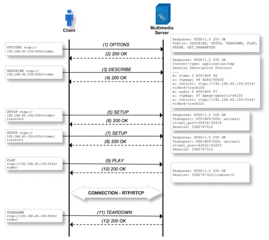
RTSP
The RTSP protocol is an application level protocol as RTP, which is used for control-ling the delivery of data with real-time properties. It provides an extensible framework that enables controlled, on-demand delivery of real-time data, such as audio and video. This protocol is intended to control multiple data delivery sessions and provide means for choosing what is the best transport protocol stack to use. This protocol stack usu-ally specifies two different protocols to use, the lower transport protocol TCP/UDP or the high level protocol RTP. RTSP consists of an exchange of text messages between the client and the server, similar to Hypertext Transfer Protocol (HTTP) [56]: the clients sends request messages, and the server answers to each request. The protocol defines several commands for the communications between the client and the server. The most important commands are the OPTIONS, DESCRIBE, SETUP, PLAY, PAUSE and TEAR-DOWN. Figure 2.2 illustrates a message flow example between the RTSP client and the RTSP server. Later on section 3.4 more RTSP flow messages examples will be discussed.
• OPTIONS This request method inquires the method supported by the server.
Figure 2.2: RTSP Message flow example.
• SETUP This method executes the request for individual media streams (audio and video media stream). The most important field in this method is the transport field, because it contains the information about the data transport possibilities on the client side. The answer from the server also contains a transport field that actually choose one of the transport methods proposed by the client. If everything is all-right, the server generates a session identifier in response to SETUP requests.
• The PLAY command is sent to the server so that it can start sending the media stream data.
• The PAUSE request causes the stream delivery to be halted temporarily.
• A TEARDOWN request is used to stop all the media streams and freeing all session related data on the server’s side.
SIP
2. BACKGROUND ANDRELATED WORK 2.1. Network standards for multimedia
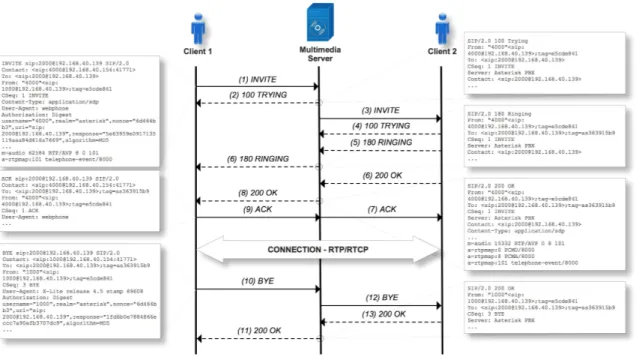
for carrying multimedia data in real time, while the SDP protocol is used for negoti-ating the capabilities of participants. SIP was adopted by 3rd Generation Partnership Project (3GPP) as a signalling protocol in IP Multimedia Subsystem (IMS) [47] control architecture. The target applications of this protocol architecture are the signalling and call control for Voice over Internet Protocol (VoIP) [87], with the possibility of integrating other services, such as Internet Protocol Television (IPTV) [98]. As before, this protocol defines a set of specific methods: INVITE, BYE, OPTIONS, REGISTER, CANCEL, ACK. Figure 2.3 illustrates the use of these messages. More detailed information about SIP messages is given in section 3.4.
Figure 2.3 shows an example of SIP operation, where a client is inviting another client for a call. SIP client A sends an INVITE message for client B, which normally is sent via a proxy server. The server finds out that client A and client B are in the same network so it forwards this message directly to client B. Client B receives this message and returns an OK message to client A via the proxy server. The call between client A and B is estab-lished after client B receive the ACK message.
Figure 2.3: SIP Message flow example.
• REGISTER Gives information about the location of user to the SIP registration server.
• The INVITE request is used to invite the End User to join in a VoIP call. The header field usually consists of the addresses of the person calling, and the intended re-ceiver, it gives information such as, the subject of the call, features to be used, pref-erences and routing information. The body field contains an object that gives infor-mation of the media content of the session. It gives inforinfor-mation on what ports and what protocols are used to send media.
• The BYE message is used to disconnect a connection between two users in a VoIP call.
• ACK is used to maintain reliable message exchanges and it is used in response to invitations.
• CANCEL is used to terminate a particular request.
SDP
The SDP specifies a format for describing multimedia sessions, aimed at the announce-ment and the call session, the session description of attributes, among others. Its syntax is text-based. It is used together with other protocols as SIP and RTSP. The SDP includes information on streams (like audio or video), the formats used, the source and destina-tion addresses, ports (to send and receive), the start and end times of the session, the originator, the level of quality, the number of video pictures per second, among others. In section 3.4 is showed an example of an SDP message.
2.2
Multimedia services
2. BACKGROUND ANDRELATED WORK 2.2. Multimedia services
three multimedia services and their delivery over an IP network to end users: IPTV, Video on Demand (VoD) and VoIP.
Video
Internet Protocol Television (IPTV)
Internet Protocol Television (IPTV) has a lot of different definitions in literature and also in practice, resulting in ambiguous interpretations of the concept. In this thesis the ref-erence from International Telecommunications Union Telecommunications Standardiza-tion Sector (ITU-T) is used as definiStandardiza-tion for IPTV [74].
"IPTV is defined as multimedia services such as television/video/audio/text/graphics/data deliv-ered over IP-based networks managed to support the required level of QoS/QoE, security,
interac-tivity and reliability."
The main features of IPTV service are: the distribution of IPTV content over an private IP network; the delivery of standardized video formats; the delivery of multiple tents/channels; and the continuous streaming of content. To deliver these features con-tinuously, the IPTV distribution network has to be carefully planned and designed. This is only possible using a private network managed by the provider and the use of multi-cast technology. Multimulti-cast reduces the use of network resources between the video server and the customer, by sending only a single copy of the media packets into the network. The network will replicate the stream to individual subscribers closer to the edge, saving this way bandwidth in the main core and also all traffic will be controlled by ensuring adequate levels of QoS [108].
services are:
• IPTV services use an end-to-end or semi-closed network
IPTV services are provided by one service provider, who is also responsible for cre-ating the means of making the IPTV available. In other words the service provider is responsible for creating/providing the network infrastructure, the access to the content and the decoder to access, receive and display the IPTV content.
• IPTV services availability are geographically bound
The IPTV services are only deployed at locations where the service provider has full control of the infrastructure and also where the network offers enough bandwidth for the complete delivery of IPTV services.
• IPTV services are service provider driven
Normally the IPTV subscriber uses services offered by the service provider, the user himself does not offer any kind of services.
• IPTV services make use of access and admission control
Before a user can use IPTV service, the user has to be authenticated, in order to have full access rights over the content. Furthermore the service will only be available when the infrastructure has sufficient bandwidth to correctly deliver the service.
The main differences between IPTV and Internet TV are summarized in Table 2.1:
Table 2.1: A comparison of IPTV and Internet TV services.
IPTV Internet TV
Users Requires IPTV infrastructure Anyone with Internet access
QoS Guarantees Yes No
Security Yes No
Distribution Network Closed Open, Internet
Video Formats MPEG-2/MPEG-4 H.264 Windows Media/Flash Video/H.264
Mobility Yes No
Content access Subscription Free
Typical IPTV services can be divided into three main groups [75]:
2. BACKGROUND ANDRELATED WORK 2.2. Multimedia services
view the program that the television station is currently broadcasting. IPTV broad-cast television is similar to television broadbroad-cast, the difference lies in the distribu-tion method: IPTV broadcast television uses IP multicast transport. The subscriber can select from numerous live television broadcasts, which are being transmitted using multicast delivery.
• Video on Demand: VoD services are described in the section bellow.
• Time-shifted TV: Time-shifted TV is a combination of linear broadcast TV and VoD. It provides a flexible viewing window for television broadcasts, allowing users to watch the beginning of a program, when the broadcast has actually already started.
Video on Demand (VoD)
VoD is a relatively well-known concept. The term of VoD is widely used for systems that allow watching video content via communications systems like Internet or cable TV. VoD allows video contents to be available on previous request from users, that is, the user can select the exact program that he wishes to see at any given time. Typically, the contents are available as pre-recorded files located in streaming servers [112]. This method of delivering video contents has several advantages such as [46]:
• The video contents are available in the transport network, only when the user asks to consume them, saving this way resources for another tasks.
• The security of this type of service - when the user asks for a service, the application system can easily identify if the client is valid, and when to allow the access to the content.
• It allows the use of video control commands, such as pause, volume up and down or fast-forward.
VoD services are segmented into several categories, classified by the allowing level of interactivity [94]:
• Live Broadcast (No-VoD):
The user is a passive participant and has no control over the session. One example of this type of VoD is the traditional TV broadcast channels.
• Pay-per-view (PPV):
Viewers sign up and pay for a specific program but still cannot make any influence on the way, when or how the content is shown.
• Quasi Video on Demand (Q-VoD):
Viewers can be grouped, based on a threshold of interest. The users have rudi-mentary level of temporal control activities by the ability of changing to a different group. For example, viewers interested in sport events are joined in a group where soccer games are broadcast.
• Near Video on Demand (N-VoD):
Services where functions like forward and reverse are simulated by transitions in discrete intervals of time (on the order of 5 minutes). This capability can be pro-vided by multiple channels with the same programming skewed on time.
• True Video on Demand (T-VoD):
Viewer has complete control over the session presentation. The user can jump to any position and perform operations like forward and reverse, play, freeze and random positioning. This service has one unique streaming for each client who is granted access to the media content. This means that several customers can start watching the media content whenever they want.
From now on, in this thesis VoD is synonymously referred to a T-VoD system.
IPTV Standards and Architectures
2. BACKGROUND ANDRELATED WORK 2.2. Multimedia services
such as ITU-T, ETSI Telecommunications and Internet converged Services and Protocols for Advanced Networking (TISPAN), Open IPTV Forum (OIF) and Alliance for Telecom-munications Industry Solutions (ATIS). A brief overview of the IPTV standards is made in table 2.2 .
Table 2.2: IPTV Standardization overview [62].
Name Focus
DVB Over IP Networks IPTV and interactive television, primarily for broadcast-ers
ITU-T Focus Group IPTV Definition of IPTV standard
ETSI TISPAN IPTV IPTV based on IMS and referencing relevant standards for
the transport layer
ATIS IPTV Interoperability Forum IPTV for cable-TV providers
IETF Defines protocols for IPTV (e.g. SIP, RTSP, RTP)
Open IPTV Forum End-to-end IPTV service, including interaction and qual-ity of service
• DVB Over IP Networks:
Digital Video Broadcasting over Internet Protocol (DVB over IP), provides a set of technical specifications that cover the delivery of Digital Video Broadcasting (DVB) MPEG-2-Based services over bi-direction IP networks, including specifications of the transport encapsulation of MPEG-2 services over IP and the protocols to access such services [7].
• ATIS IPTV Interoperability Forum:
• IETF:
The Internet Engineering Task Force (IETF) is responsible for the definition of proto-cols that IPTV standards use such as SIP for session control, RTSP for media control of VoD services, Internet Group Management Protocol (IGMP) for IPv4 multicast-based services and RTP for media delivery.
• Open IPTV Forum:
The Open IPTV Forum (OIF) is an initiative with the objective of working with other standardization bodies to define a common and open end-to-end solution for supplying a variety of IPTV services across a wide variety of different network architectures [62].
• ITU-T Focus Group IPTV:
ITU-T Focus Group IPTV has been created with the mission of coordinating and developing the global IPTV standard architecture based on a client-server architec-ture with the addition of a service delivery platform while considering the flowing key areas: DRM, QoS/QoE, meta-data and interoperability [76].
• ETSI TISPAN IPTV:
The ETSI/TISPAN emerged with the mission of developing specifications for the next generation wireless and fixed networking infrastructures, defining IPTV as a NGN service and using the IMS. This architecture can connect to legacy networks via gateways that make part of the IMS or any other SIP-based architecture [62].
Two main architectures have been approved for IPTV delivery: they are the ITU-T Focus Group IPTV Architecture and the ETSI TISPAN IPTV Architecture.
ITU-T Focus Group IPTV Architecture
2. BACKGROUND ANDRELATED WORK 2.2. Multimedia services
consumers with services; and finally the content provider domain that owns the content or has a license to sell contents or content assets. Figure 2.4 shows the domains responsi-ble for the provision of IPTV services over a NGN [107].
Figure 2.4: IPTV domain model [93].
The ITU-T identifies three IPTV architecture approaches that enable the service providers to deliver IPTV services, they are: the NGN IPTV architecture, the NGN-based non-IMS IPTV architecture and the NGN non-IMS-based IPTV architecture [73].
• Non-NGN IPTV Functional Architecture (Non-NGN IPTV): The Non-NGN IPTV architecture is based on the existing network components and protocols/interfaces. The use of this approach generally requires a separate service control and an appli-cation layer developed specially for the IPTV services.
• NGN-based non-IMS IPTV Functional Architecture (NGN-Non-IMS IPTV): The NGN-Non-IMS IPTV architecture uses components of the NGN framework refer-ence architecture as defined in [ITU-T Y.2012 [81]] to support the provision of IPTV services, in conjunction with other NGN services. This approach uses a dedicated IPTV subsystem within the NGN to provide the necessary IPTV functionalities.
Service User Profile Function Block are defined in [ITU-T Y.2021 [72]] to provide service control functions.
The IMS-based and the non-IMS-based approaches only differ in terms of the inclusion of the core IMSService Control Functions (SCF)in the IMS-based IPTV solution. TheIMS Coreprovides a SIP-based session management for all types of application, and a common charging mechanism for all applications.
2. BACKGROUND ANDRELATED WORK 2.2. Multimedia services
Figure 2.5: ITU-T NGN-IMS-based IPTV Architecture [73].
ETSI TISPAN IPTV Architecture
The ETSI/TISPAN follows a parallel approach to ITU-T classifying IPTV architecture into the NGN-based non-IMS IPTV architecture and the NGN IMS-based IPTV architecture. In addiction, it considers two subsystems that are responsible for the Transport Control Functions: theResource and Admission Control Subsystem (RACS)and theNetwork Attach-ment Subsystem (NASS). The first one is responsible for the police manageAttach-ment and
im-plementation, ensuring that the user is allowed to access the services being requested. It also reserves and allocates the required and subscribed amount of bandwidth for the service. The second one (NASS) is responsible for provisioning the IP address and other configurations of the terminal, as well as authentication and authorization of the sub-scriber. Both NASS and RACS form an integral part of the NGN [16].
IMS-based functional architecture for IPTV services
The main functions and reference points defined in ETSI/TISPAN NGN IMS IPTV con-cept are, the SCF, the Media Control Functions (MCF) and the Media Delivery Functions (MDF)[16].
As showed in figure 2.6, the User Equipment (UE) can communicate with the IPTV ap-plication servers (includingSCF) over various interfaces for different proposes, namely, over Gminterface via theIMS Corefor session management propose, directly over aUt interface for the service profile configuration purpose, or over theXainterface to interact with service selection functionalities. EachUEhas at least four interfaces for media con-trol overXcand media delivery overXd, as well as theGminterface to theIMS Coreand theUtinterface toIPTV Application Service Functions (IASF). MCFcan controlMDFover Xp interface, that also allows building a really scalable and distributed media delivery infrastructure.
IMS Core elements
The IMS Core specification comprises two main nodes: the Call Session Control Func-tion (CSCF)and theHome Subscriber Server (HSS). TheCSCFis the heart of the IMS archi-tecture and is used to process SIP signalling. The main function of theCSCFis to provide session control for terminals and applications using the IMS network. Three types of CSCFare defined:
• TheProxy-CSCFthat is the first contact point for the IMS users. The main goals of the P-CSCF are to guarantee the signalling messages between the networks and subscribers and the resource allocation for media flows by interaction with the RACS.
• The Serving-CSCFis the main control entity within the IMS. It processes registra-tions from subscribers and stores their current location and also is responsible for subscriber authentication and session management. Subscriber policies stored in theHSScontrol the operations performed by theS-CSCFfor a particular subscriber.
2. BACKGROUND ANDRELATED WORK 2.2. Multimedia services
user and subscriber information to support the network entities handling calls and sessions.
Service Discovery and Selection
TheService Discovery Function (SDF)andService Selection Function (SSF)provide the nec-essary information that is required for anUEto select an IPTV service. TheSDFis re-sponsible for providing service attachment information about accessible IPTV services (personalized service discovery). TheSSF is used to provide service selection informa-tion, as well as personalized user preference information.
IPTV Service Control Functions
IPTVSCFis responsible for handling the IPTV related requests and execute service and session control of all IPTV services. These functions are also responsible for interworking with theIMS Coreon the service layer.
Voice
Voice over Internet Protocol (VoIP)
Voice Over Internet Protocol (VoIP) may be defined as a set of technologies and compo-nents that together, offer the user the possibility of establishing voice calls through an IP network[52].
Traditional phone networks, known as Public Switched Telephone Networks (PSTN) use circuit-switching technology. In circuit-switch, resources are reserved along with the entire communication channel for the duration of the call. On the other hand, IP uses packet-switching, where the information is digitally transmitted using individual pack-ets. Packets know their destination and may be able to arrive via different paths.
VoIP allows users to make voice calls to other VoIP users but also to traditional users (PSTN users). Through VoIP these users will obtain various additional services beyond voice calls, including voice mail, fax, Iteractive Voice Response (IVR), conferencing call and instant message[50].
VoIP has very strict network delay requirements, so for guaranteed QoS VoIP we should use private IP networks intended for voice traffic or use VoIP service providers (in this case an internet connection with traffic differentiation is preferable).
VoIP Architectures
Figure 2.7 presents a generalized model of a VoIP network. While the details of various protocols differ, all major VoIP architectures are sufficiently similar so that their major features can be described uniformly.
2. BACKGROUND ANDRELATED WORK 2.2. Multimedia services
Figure 2.7: Generalized model of VoIP architecture [104] .
server or end system to which the request should be sent.
The two VoIP architectures, SIP and H.323, are based on similar concepts. The tables 2.3 and 2.4 show the components and protocols of the two approaches. Both architectures comprise a lot of analogies with respect to function split and service location. In SIP as well as in H.323, basic call and feature control are performed in the terminals. For fea-tures requiring network support, servers are foreseen in the networks [85].
Table 2.3: SIP and H.323 components [85].
Client Network Servers
SIP (IETF) User Agent Proxy Server Registration Server Redirect Server
H.323 (ITU-T) Terminal Gatekeeper MCU Gateway
Table 2.4: Protocols used by H.323 and SIP [85].
Real-Time Data Transmission Call Control
SIP (IETF) RTP/RTCP SIP and SDP
H.323 (ITU-T) RTP/RTCP H.225 and H.245
Information about H.323 can be found in appendix A.2.
SIP
The basic elements that compose a SIP architecture are: the User Agents and the Network Servers. There are tree types of servers within a network: A Proxy Server, a Registration Server and a Redirect Server [104].
and negotiate the characteristics to establish a session. Each User Agent is com-posed of two parts: a client and a server. the client portion is called the User Agent Client (UAC) and it is the part that sends requests and receives responses. The server portion is called the User Agent Server (UAS) and it is the part that receives requests and sends responses. For example, when an entity is initiating a call, the User Agent behaves like UAC when sending the INVITE request and receive re-sponses to the request. For anyone who receives a call, the User Agent behaves like UAS when receiving an INVITE request and sends responses.
• Proxy Server: The proxy servers act as an intermediary program, receiving requests, forwarding them to the next server. A proxy server also provides mechanisms for authentication and accounting.
• Registration Server: The Registration Server is a SIP entity that receives user records, extracts information about their current location and stores them into a location database. The propose of the database is to map sip:[email protected] to some-thing like sip:[email protected]:5060 latter used by the Proxy Server.
When the proxy receives an INVITE to sip:[email protected] the address transla-tion will search in the locatransla-tion database by the real address (sip:[email protected]:5060), the INVITE will be then redirect to there.
2. BACKGROUND ANDRELATED WORK 2.3. Quality measurement
2.3
Quality measurement
User experience
The delivery of multimedia services requires different levels of quality like limited jitter or delay, or a significant amount of bandwidth in order to operate properly. Although, independently of the specific requirements that this services can have, QoS is just a com-ponent of the overall QoE; a significant part of it is dictated by psychological effects [88]. ETSI identifies the main components of the user experience as: the technical mea-sures related to QoS and the subjective and objective psychological meamea-sures. Objective psychological measures can be, for example, measurements on user effectiveness and efficiency. On other hand, subjective psychological measurements are related to the sub-jective evaluation given by the user and are expressed in terms of degrees of satisfaction [12].
QoE has a lot of different definitions, however the standardization groups recognized the need for contextualizing the meaning of it:
• ETSI defines QoE as a measure of user performance based on both objective and subjective psychological measures when using service or product within the do-main of Information and Communication Technologies (ICT). ETSI says that QoE is a measure of both the process and the outcomes of communications, and that technical parameters like QoS should be taken into account along with specific con-text variables [12].
• ITU-T defines QoE as being the overall acceptability of an application or service, as perceived subjectively by the user in an end-to-end context. Although ITU-T makes a remark that the user expectations and circumstances may influence the judgement [78].
To show the effect of different kinds of impairment, it is necessary to have a brief descrip-tion of the major common impairments in multimedia services [88][66]:
is often caused by an excessive data loss during the execution of the compression algorithm. Recent codec methods like H.264 have a deblocking filter in order to reduce the visibility of this kind of artefact.
• Blurring: Global distortion of the entire image, characterized by reduced sharpness of edges and spatial detail. The image appears unfocused. It is due to the suppres-sion of higher frequency coefficients by the quantization process.
• Busyness: Spatial edge noise, is a variable distortion occurring on the image edges.
• Noise: There are two types of noise: Mosquito noise that is a form of edge busy-ness distortion usually associated with movement and characterized by moving artefacts and/or blotchy noise patterns superimposed over the objects, and Quan-tization noise that looks like snow effect, similar to a random noise process but not uniform over the image.
• Jerkiness: Motion that was originally smooth and continuous perceived as a series of distinct snapshots.
• Loss of information: In video the loss of reference will cause the appearance of black spots in the image, in audio it will result in an interruption of sound for a certain period of time.
• Echo: When part of the data sent in a bidirection channel return to the sender. This happens when a proper echo cancellation mechanism is not in use or if the delay is too big.
• Double Talking: When the delay its too big, data may be sent in two different direc-tions at the same time.
• Time shifting: when a content is moved ahead in time.
• Packet discard at reception: When packets delay is too big, the packets are useless for a correctly stream decoding, so they are discarded.
2. BACKGROUND ANDRELATED WORK 2.3. Quality measurement
• Wrong synchronization between video and audio: This occurs because of different propagation delays for audio and video channels. Another reason is the error in the coding/decoding process.
Multimedia services
Quality of Service
QoS is a key requirement in IP-based multimedia applications. Its fundamental objective is to ensure predictable behaviour and high level of performance of the IP network. Dif-ferent applications have difDif-ferent requirements regarding the handling of their traffic in the network. Applications generate traffic at various rates and this generally requires the network to be able to carry this traffic at the same rates that it is generated. In addition, applications are more or less tolerant to traffic delays in the network and to variation in traffic delay. Certain applications can tolerate some degree of traffic loss while others cannot. These requirements are expressed using the following QoS-related parameters: bandwidth, losses, jitter and delay [115].
The required bandwidth is related to the rate in which an application must be carried by the network. This calculation is complex because it is inherent to the content variation. However it is possible, if requested, for the video coder to generate different types of Bit Rates, in order to achieve a more adequate traffic variation. Requirements on losses and delays must be strictly obeyed because these regard to the period of time that an application can tolerate in delivering a packet of data. Small drops in packets can impair a significant number of video frames. On most cases, jitter is satisfactory when an adequate buffer size is established [88].
Quality of Experience
The QoE is defined as the overall acceptability of an application or service, perceived sub-jectively by users. QoE is a measure of end-to-end performance at the services level from the user perspective and an indication of how well the system meets the user’s needs. The recommendation of the ITU-T defines QoE requirements from the user’s perspective, in order to be agnostic to the transport network and the protocols used [78].
There is a nonlinear relation between the QoE subjective measurement as measured by the perceptual impact of forms of service degradation and the QoS objective parame-ters. Typically, when the QoS disturbance parameter increases, the QoE metric and user perception of quality decreases. 2.8.
Figure 2.8: QoE relationship with QoS [1].
2. BACKGROUND ANDRELATED WORK 2.3. Quality measurement
Table 2.5: Impairments to video and audio services (Based on [88]).
Service Coding and
Compression Transcoding Delay Jitter
Losses and Transmission Errors VOIP Loss of information, Jerkiness, Block distortion Loss of information, Noise Echo, Double talking Time shifting, Packet discard at reception Jerkiness IPTV Loss of information, Jerkiness, Block distortion, Busyness Loss of information, Noise, Blurring Time shifting, Slow channel navigation, Impaired video/au-dio sync. Time shifting, Packet discard at reception Blank spots, Jerkiness VOD Loss of information, Jerkiness, Block distortion, Busyness Loss of information, Noise, Blurring Time shifting, Impaired video/au-dio sync. Time shifting, Packet discard at reception Blank spots, Jerkiness
Standards and models for video quality assessment
The QoE can be assessed in several ways, in the particular case of video, image quality can be assessed in three ways[1]:
• Subjective measurements: Using an experimental evaluation method where a num-ber of participants assign a rating on a predefined scale of values.
• Objective measurements: Analysing parameters of the video signal (eg, Peak-to-peak Signal-to-Noise Ratio (PSNR), Mean Square Error (MSE)) using specialized measuring equipment. Compare the video signal that is transmitted over the net-work with the source video signal.
• Indirect measurements: Performing measurements of various network parameters (delay, jitter, packet loss) for the purpose of estimating the impact of these parame-ters on the visual quality using the relationship between QoS and QoE.
overview of the main quality assessment methodologies.
Subjective quality assessment involves human participation subjects and controlled view-ing experiments, with standardized equipment in order to achieve results. Due to the high level of complexity of the subjective assessment process, an electronic approach is often used, where a software measures various aspects of video signal and predicts the user satisfaction using objective measurements [88].
Figure 2.9: Classification of media-layer objective and subjective video quality models [49].
Subjective quality assessment
2. BACKGROUND ANDRELATED WORK 2.3. Quality measurement
using training and controlled environments. Yet it is important to remember that a qual-ity score is a noisy measurement that is defined by a statistical distribution rather than an exact number. The most used subjective assessment technique is the Mean Option Score (MOS).
MOS is a subjective measurement indication, which ranks the video quality based on the user feedback. In MOS users determinate the quality by rating the quality of the video displayed on a scale of 1 (very bad) to 5 (very good) as showed in Table 2.6. This scale is used when users are rating videos with single sequences without comparing them with a video reference.
On the other hand, table 2.7 shows a scale to establish a relative judgement between a pair of video sequences to evaluate degradation of the image[117].
Table 2.6: Quality and Impairment scale with MOS conversion [88].
MOS Perceived Quality Impairment
5 Excellent Imperceptible
4 Good Perceptible, but not annoying 3 Fair Slightly annoying
2 Poor Annoying
1 Bad Very annoying
Table 2.7: MOS scale for the comparison between samples [88].
Score Impairment
-3 Much worse -2 Worse
-1 Slightly worse 0 The same +1 Slightly better +2 Better
+3 Much better
The main drawbacks of this approach are: it is expensive in cost, time consuming, cannot be used in real time and lacks repeatability. These limitations motivated the development of objective tools that predict subjective quality solely from physical characteristics.
Objective quality assessment
Video objective assessment methods can be mapped into five different models depend-ing on the type of input information that is bedepend-ing used for quality assessment, as listed in Table 2.8 [111].
• Media layer model: This model uses video signals to approach human quality
benchmarking, focusing on the emulation of Human Visual System (HVS). It does not require any information about the system under testing, such as codec type or packet loss rate, so it can be applied to the evaluation of unknown systems such as codec comparison and/or optimization. However if media signals are not avail-able, this model cannot be used.
• Parametric packet layer: Predicts QoE only from the packet header information,
and is not adequate to judge content-related features like distortion or to monitor individual user flows. It does a lightweight measurement solution for predicting QoE that does not include inspecting the media signals. This type of model is aimed for real-time non-intrusive monitoring at the network layer. Possible examples for the use of this model are the evaluation of services as VoD or IPTV.
• Parametric planning model:This model makes use of quality planning parameters
for networks and terminals in order to predict the QoE. However this type of model requires a priori information about the system under testing. A good example for the use of this model is the ITU-T Recommendation G.107, the E-Model [79], which has been used as a network planning tool for the PSTN, but recently it was adopted to the planning of VoIP and IPTV networks [111].
• Bitstream layer model: This model is a recent concept; it occupies a position
be-tween the Media layer model and the Packet layer model. This model obtains the QoE by extracting and analysing content characteristics from the encoded bitstream and from the packet layer informations that is used in the packet layer model. This model is a useful non-intrusive monitoring with the advantage of allowing QoE monitoring for individual users.
• Hybrid Layer: It is a combination of the previously mentioned models. It is
2. BACKGROUND ANDRELATED WORK 2.3. Quality measurement
the QoE. This model is also aimed at non-intrusive monitoring, however accepts a combination of different types of inputs.
Table 2.8: Categories of objective quality assessment models (Based on [111]).
MODELS
Media Layer Parametric
Packet Layer Parametric Planning Bitstream Layer Hybrid Input
in-formation Media signal
Packet header information Quality design parameters Packet header and payload in-formation Combination of any Application scenario Quality benchmark-ing In Service non-intrusive monitoring (e.g. Network probe) Network planning terminal/ application designing In Service non-intrusive monitoring In Service non-intrusive monitoring
In the scope of this thesis, our attention was focused on the media layer model because the media layer quality model approximates the human subjective evaluation, which al-lows us to access the contribution of objective QoS in the overall perceived quality of video.
Media Layer Model
Media Layer Model estimates the audio and/or visual QoE by using media signals such as the speech waveform and video pixel data. Table 2.9 shows the ITU-T recommenda-tions for media layer model[111].
Table 2.9: ITU-T Recommendations for objective assessment methods.
Service Type Media layer model
Voice ITU-T P.862 Audio (general) ITU-R BS.1387
Video ITU-T J.341 (HD)ITU-T J.144 (SD) ITU-T J.247 (PC) Multimedia ITU-T J.148
cannot be used to evaluate the effects of packet loss, which is one of the most important quality factors in recent applications. For video ITU-T standardized recommendations J.144 [70], J.341 [82] and J.247 [77]. The first standard describes techniques for objec-tive estimation of the perceptual video quality for digital cable television when Full-Reference (FR) is available. Recommendation J.247 does the same for general multimedia video and J.341 for HDTV. Last but not least, recommendation J.148 defines the require-ments for multimedia perceptual model for audio-visual services [88].
Objective measurements compare the output video signal with the source video signal in order to find the differences. These differences are used to define how the decoded stream derives from the original. Greater differences between the original and the de-coded stream are associated to lower quality of the received stream. The Media layer objective quality assessment methods can be further categorized to three different ap-proaches: FR, No-Reference (NR) or Reduced-Reference (RR) depending on the quantity of information about the reference that is used to assess the quality [70].
• Reduced Reference (RR): RR method evaluates the video quality by comparing processed video, subjected to distortion by coding and transmission losses, with a small amount of information extracted from a source video (Figure 2.10). Since RR method uses features from the source video and degraded video signal, this evaluation is fairly accurate. RR model assumes that a side channel is available to transmit the reference signal parameter data.
Figure 2.10: Reduced Reference method.
2. BACKGROUND ANDRELATED WORK 2.3. Quality measurement
the source video, it can be used in environments where the source stream is not available, which typically is the case of IPTV or broadcast TV. This method is less accurate because it does not use information from the source.
Figure 2.11: No Reference method.
• Full Reference (FR): The FR method compares the information of the source video (before any distortion has occurred), with the processed video after distortion caused by the coding and transmission losses, in order to objectively evaluate the degraded video (figure 2.12). Since the FR model compares source video with processed video, it provides a highly accurate objective assessment of the quality, reflecting its basic characteristics. The FR method is best suited for video quality metrics for VoD networks. However, it needs a large amount of resources in order to obtain data from the original video and to make a valid comparison.
Figure 2.12: Full Reference method.
Some examples of metrics for FR assessment are showed below:
Mean Square Error (MSE)is computed by averaging the squared intensity of the
the original and the distorted image in a pixel basis as showed in equation 2.1.
M SE= 1
M.N M X i=1 N X j=1
[f(i, j)−F(i, j)]2
(2.1)
WhereM.N is the number of pixels in the image or video signal, f(i, j)is the original signal at pixel(i, j)andF(i, j)its the reconstructed signal.
The Peak-to-peak Signal-to-Noise Ratio (PSNR)is a mathematical measure that is
com-puted by taking the Root Mean Square (RMS) value from the differences (errors) of the original and the received video frames, often normalized to be expressed in dB. The value of PSNR can be calculated using equation 2.2,
P SN R= 10.log10
s2
M SE
[dB], (2.2)
where s is maximum possible pixel of the image, when the pixels are represented using 8 bits per sample,s= 255(28
−1 = 255).
Video Quality Metric (VQM) is an HVS metric and measures the perceptual effects of
different kinds of video impairments such as blurring, jerky motion, block distortion, global noise and combines them into a single metric. VQM has a high correlation with subjective quality assessment.
![Figure 2.5: ITU-T NGN-IMS-based IPTV Architecture [73].](https://thumb-eu.123doks.com/thumbv2/123dok_br/16576160.738279/49.892.156.778.132.547/figure-itu-t-ngn-ims-based-iptv-architecture.webp)
![Figure 2.6: TISPAN NGN-IMS-based IPTV Architecture [16].](https://thumb-eu.123doks.com/thumbv2/123dok_br/16576160.738279/51.892.187.742.628.1060/figure-tispan-ngn-ims-based-iptv-architecture.webp)
![Figure 2.9: Classification of media-layer objective and subjective video quality models [49].](https://thumb-eu.123doks.com/thumbv2/123dok_br/16576160.738279/60.892.130.735.348.647/figure-classification-media-layer-objective-subjective-quality-models.webp)
![Figure 3.7: VOIP Module (based on [13]).](https://thumb-eu.123doks.com/thumbv2/123dok_br/16576160.738279/84.892.101.738.130.628/figure-voip-module-based-on.webp)