MAI Suppression with joint
Pre-distortion filtering and Transmit Diversity
Mário Marques da Silva, Américo M. C. Correia Institute for Telecommunications
IST, Torre Norte 11.10, Av. Rovisco Pais, 1049-001 Lisboa, Portugal [marquesilva@mail.telepac.pt]
Abstract – It is intended to specify a new pre -distortion (PD) filtering technique to be used with a RAKE
Receiver, which can be used to combat the Multiple Access Interference (MAI), combined with two kinds of Transmit Diversity (TD), namely the Selective Transmit Diversity (STD) and the Space-Time Transmit Diversity (STTD) for high data rate transmissions over frequency selective Rayleigh fading channels. By pre -distorting the signals to be transmitted by the Base Station (BS) with a Minimum Variance (MV) algorithm, the orthogonality between the desired signal and all interfering signals can be improved. We combine the PD with STD and with STTD, allowing a reduction in the MAI and combating the fading. The increase in performance is achieved with a small increase in power processing in the BS, avoiding any need to increase complexity in the Mobile Station (MS).
Keywords – W-CDMA, MAI Cancellation, Pre -distortion filtering, Selective Transmit Diversity,
Space-Time Transmit Diversity.
I. INTRODUCTION
Much research has been undertaken in the area of the Multi-User Detectors [1,2] for Direct Sequence Code Division Multiple Access (DS-CDMA) technology. It can be mainly used by Base Stations (BS) where there is enough power processing capability and where it is easier to know/estimate the uplink Channel State Informations (CSI) and the spreading sequences of interfering users. However, the trend of the telecommunications is to become more and more asynchronous and with higher data rates in the downlink than in the uplink. This is necessary for services like Web browsing, Data Base Access, Multimedia, etc. To obtain this, it is important to transfer the complexity as much as possible to the BS, where the power processing and electrical power available is higher, so as to combat the several sources of interference.
With the aid of pre-distorting the signals to be transmitted by the BS, the orthogonality between the signals seen by the different users can be improved [3]. The proposed PD filtering is done taking into account the spreading sequences and the Channel Impulse Responses (CIR) of the users present in the cell. The current approach considers a RAKE receiver in the MS. The proposed system can be seen as a simple alternative to beamforming, presenting a much lower complexity, without any increase in physical dimensions and, hence, with an easier practical implementation.
This paper is structured as follows. Section II presents the system models for the PD filtering, STD and STTD. Section III presents the performance results and analysis for the proposed schemes. The key findings of this paper are then summarized in Section IV.
II. SYSTEM MODELS FOR THE PRE-DISTORTION FILTER, STD AND STTD
A. System Model for the Pre-distortion filter
With the proposed scheme, the loss of orthogonality in the MS due to different spreading sequences and CIRs can be reduced. These are the cross-correlations that we intend to estimate and to minimize by pre-distorting the signals, before transmission, in the BS.
The PD is done taking into account the spreading sequences and CIRs of the different users present in the cell considering that the MS has a RAKE receiver to mitigate the effects of the channel and to provide multipath diversity. Advanced W-CDMA networks consider the need to have knowledge about CIRs also to provide power control.
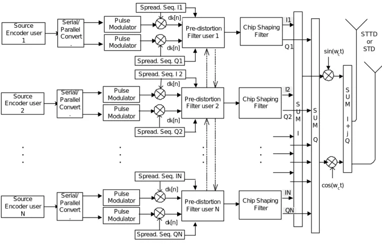
The proposed system is shown in Figure 1, where the PD filter is included in the CDMA-QPSK modulator of the BS, jointly with TD technique (STD or STTD).
The PD filter is implemented based on the Finite Impulse Response (FIR) philosophy. The proposed transmitter filter is:
[ ] [ ]
0 1 1 Tq q q q g
g =g g ⋅⋅⋅g L − (1)
Source Encoder user 1 Pulse Modulator Pulse Modulator Serial/ Parallel Convert . Pre-distortion Filter user 1 cos(wct) sin(wct) Spread. Seq. Q1 Chip Shaping Filter I1 Q1 Source Encoder user 2 Pulse Modulator Pulse Modulator Serial/ Parallel Convert . Pre-distortion Filter user 2 Chip Shaping Filter Spread. Seq. I1 Spread. Seq. I 2 Spread. Seq. Q2 Source Encoder user N Pulse Modulator Pulse Modulator Serial/ Parallel Convert . Pre-distortion Filter user N Chip Shaping Filter Spread. Seq. IN Spread. Seq. QN S U M I . . . . . . . . . . . . I2 Q2 IN QN S U M Q S U M I + j Q STTD or STD dk[n] dk[n] dk[n] dk[n] dk[n] dk[n]
Figure 1 - Scheme of a CDMA-QPSK modulator with combined pre-distortion filter and TD
We introduce Hq as a L0×Lg channel Toeplitz matrix, denobed by t (h Lq; g), where hq is the CIR of the user q. A Toeplitz matrix ( ; )
g
x L
t , where x=[x x1 2⋅⋅⋅xr], is defined as:
( )
1 1 1 1 . . . . . . ; . . . . . . r L r r L r x x x L x x + − + − = 0 0 t (2)being 0r the r×1 column vector of all zero elements. We define the received signal sq k, [ ]n at the qth MS due to the kth transmission as [3]:
[ ]
[ ] [
]
(
)
, , , 1 , 1 0 2 T q k q k q k q k s m =s mN s mN + ⋅⋅⋅s m+ N+L − (3)being L0=M +Lg−1, being Lg the length of the FIR filter and being M the maximum delay spread expressed in chip intervals. Assuming that the maximum delay spread is smaller that the symbol period the vector sq k, [ ]m can be
expressed as [3]:
[ ]
(0) (0)[ ]
( ) ( )[ ]
( ) ( )[ ]
, 1 1 L L l IPI l IPI q k k q k k k q k k k q k k l l s m b m b m − b m = = =C H g +∑
C H g +∑
C H g (4)where the Toeplitz matrix Ck[ ]m of size (N+L0− ×1) L0 is written as:
[ ]
(
)
[ ]
[ ]
[
]
[
]
[ ]
[
]
[ ]
[
]
[ ]
[
]
[ ]
[ ]
[
]
[ ]
[ ]
[ ]
[ ]
[ ]
[ ]
[ ]
[ ]
0 0 1 (0) 0 1 ( ) 1 ( ) ; 1 2 0 0 1 1 0 1 1 0 0 0 0 0 0 0 0 0 0 0 0 0 0 0 0 0 0 [1] 0 0 [ l l l l k k k l k l k l k L k l k l k l k k l k l k k l l k k k k k L k l k k k k k m c c c c c c c c c c c N c m c N c N c N c N c m c c c c N τ τ τ τ τ τ τ τ τ τ τ τ τ τ − − − − − = − − + − + + = = C c L C C L L M L M L M M M L L L L L M L L L L M L t[
]
0 1 ] 0 [ ] l L− −τ c Nk ck N τl − M M M L L (5)[ ] [ ]
0 1[
1]
T k =ck ck ⋅⋅⋅ck N− c(6)
and where τ in (5) means the l delay expressed in chip intervals. l
The received signal at the input of the qth MS, from all K transmissions, is defined as [3]:
[ ]
,[ ]
[ ]
1 K q q k q k s m s m η m = =∑
+ (7)being ηq the background noise seen by the MS. The received signal at the output of the qth MS (RAKE Receiver)
is:
[ ]
( )[ ]
[ ]
( )
[ ]
( )
[ ]
[ ]
, , 1 (0) (0) ( ) ( ) , , 1 0 K H q q q k q k K L H l H IPI q k q k k q k q k k q k l L l y m s m m b m b m m χ η η = = =− ≠ = + = + + ∑
∑
∑
C v H g v H g (8)being the filter vector for the receiver filter Cq,( )χ the th
χ column (reference delay which affects the performance) of
the vector C(0)q and being [ ]m c ( ) q[ ]m H q q η η = ,χ . We define ( )l q,k
v as the covariance between the spreading sequence of the
reference qth user (with path delay l ) and the spreading sequence of some kth interfering user:
( )
( )( )
( ) (0) ( ) ( ) , , 1 ( ) ( ) , , L H l l q k k q q l H l l q k k q χ χ α = = ⋅ =∑
v C C v C C (9) χ should be 0/ 2 L for the calculation of ( ) , l q k v and ( ( )) 0 / 2 l L τ +
for the calculation of v( 0 )q k, in order to achieve the better
performance. The operation ⋅ stands for the integer part of operand. Additionally, we define Wq k, as the covariance
matrix:
( )
(
)
(0) (0) (0) , , ( ) ( ) ( ) , , H q k q q k H l IPI l q k q q k = = W H v W H v (10)In the calculation of Hq (both as (0) q H and (IPI) q H ) it is considered ( )2
(
( ) ( )) (
( ) ( ))
2 l l q q L j j l l l q q q l eθ e θ α α α − = = ⋅ ⋅ ⋅∑ , instead of the several path
coefficients, because a RAKE is employed in the receiver side, which originates an increase in the interferences. The received signal can be rewritten as:
[ ]
(
(0))
[ ]
( )
( )[ ]
[ ]
, , 1 1 0 K H K L H l q q k k k q k k k q k k l L l y m b m b m η m = = =− ≠ =∑
W g +∑ ∑
W g + (11)At the kth MS, the interfering signals due to the qth signals are given as
( )
( ) [ ] , L H l k q q q l L b m =−∑ W g . The total sum of interfering
signals to other MS, due to the qth signals comes:
[ ]
(
(0))
[ ]
( )
( )[ ]
, , 1 1 0 Q Q L H l H q k q q q k q q q q q l L q k l m b m b m = = =− ≠ ≠ = + ∑
∑ ∑
? W g W g (12)Where the second parcel of the second member corresponds to the Inter-path Interference (IPI) vectors of the proper user (k=q). In order to mitigate the interference, the filtering vector gq should be calculated to
minimizeE?k[ ]m 2, while providing distortionless response to the qth MS (reference user). The optimization based
on the Minimum Variance of Interfering Signals to Others (MVISO) algorithm is to find gq such as:
[ ]
2 min 1 q q g H q q E m subject to = ? W g (13)where Wq=Wq q(0), . There is a closed-form solution for the optimal filtering vector under the MVISO criterion in (13).
From (12) it comes [3]:
[ ]
2 (0)(
(0))
( )( )
( ) , , , , 1 1 0 Q H Q L H H l l k q k q k q k q k q q q q l L q k l E m = = =− ≠ ≠ = ⋅ + ⋅ ∑
∑ ∑
? g W W W W g (14) Considering( )
( )
(0) (0) ( ) ( ) , , , , 1 1 0 Q Q L H l l H q k q k q k q k q q q l L q k=≠ = =−l≠ = ⋅ + ⋅ ∑
∑ ∑
W W W W W (15)and using the method of Lagrange multiplier, the optimal vector under the MVISO criterion comes:
1 1 , 1, 2, ..., q q q H q q q g q K − − = W W = W W W (16)
The pre-distortion weight vector should always have unit norm, i.e., 2
1
q
g = , because of power constraints, since the
transmit power at the BS is always limited.
Because the FIR filter introduces a delay in the signal corresponding to Lg-1 samples, this delay has to be removed
after passing the signals through the pre-distortion filter.
B. System Model for STD
In typical frequency or time diversity the same signal is transmitted over different carrier frequencies or time slots. This results in a decrease in the number of bits per Hertz and a consequent loss in spectral efficiency. To maintain a high spectral efficiency, frequency or time diversity should be based on the transmission of different information symbols over the different frequencies or time slots. When the antennas are spaced sufficiently far apart, the transmission from each antenna undergoes independent fading, and thus, providing transmit diversity without reducing the spectral efficiency.
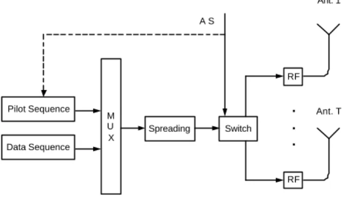
Pilot Sequence Data Sequence M U X Spreading Switch RF RF Ant. 1 Ant. T A S . . .
Figure 2 - Scheme of a Selective Transmit Diversity with FBI
The STD scheme has a low rate (750 Hz-3 kHz) feedback link from the receiver (MS) telling the transmitter (BS) which antenna should be used in transmission. There is a common or dedicated pilot sequence, which is transmitted. Different antennas with specific pilot patterns/codes enable antenna selection. Then, the transmitter has a link quality information about the T (number of antennas) links and it transmits a single symbol stream over the best antenna. The receiver is supposed to re-acquire the carrier phase after every switch between antennas. The Antenna Switch (AS) has the capability to switch every slot duration, i.e., 0.667 ms (rate 1.5 kHz).
After using STD from T antennas over the M-paths, each with equal average energy, then we have changed the probability density function for each link. The corresponding BER analytical expression is described in [5].
The decision for the antenna selection of the STD combined with the RAKE receiver (maximize multipath diversity) is done in order to select the channel which maximizes the sum of the square of the absolute values of the paths gains, i.e., to maximize the expression 2
1 max M m m α = ∑ .
C. System Model for STTD
This kind of TD scheme is spectral efficient and resistant to fading, where the base station uses T=2 transmitting antennas and the mobile only has one receiving antenna. As long as the antennas are spaced sufficiently far apart, the
transmission from each antenna undergoes independent fading. In opposition to the previously described STD, the STTD scheme belongs to the open loop class. Between the receiver antenna and each transmitting antenna there are M multipath, where each one has equal average energy. The corresponding probability density function for each link is given by [6] 1 ( ) exp( / ) , 0 ( 1)! K i i K i i f M γ γ = − −γ Γ γ > − Γ (17)
where Γ is the average signal to noise ratio of each path. The assumption of independent fading is valid if the transmitter antennas or time slots are spaced sufficiently far apart.
With the proposed STTD there are T=2 transmitting antennas and the symbols sent to them in two consecutive symbol intervals are s1 s2 in antenna 1 and -s2
*
s1 *
in the second antenna. So the received symbols in two consecutive symbol intervals are respectively:
2 * 1 2 2 1 2 1 * 2 2 1 1 1 n s s r n s s r + + = + − = α α α α (18)
r1 is the symbol arrived in the first symbol interval and r2 is the symbol arrived in the second interval. α1α2 are
complex random variables, characteristic of the single path fading channel, where the amplitude has a Rayleigh distribution and the phase is uniformly distributed in [0,2π], n1 and n2 are gaussian random variables. Note that the
mobile receiver only has a single antenna. The receiver to demodulate the signals does the following processing:
* 1 2 2 2 2 2 1 2 * 1 * 1 2 * 2 1 1 2 2 2 1 2 * 2 * 1 1 ) | | | (| ) | | | (| η α α α α η α α α α + + = − + + = + s r r s r r (19)
We see that each transmitted signal after demodulation is multiplied by the square of the channel coefficients. So, if the channel has M multipaths between each transmitting antenna and the receiver antenna then the system is able to
get a diversity order of 2M (2 is the number of transmitting antennas). When we consider a STTD order higher than two, it was shown in [7,8] that there is Intersymbol Interference (IIS) from only one symbol in the decoding of any other symbol, for a modulation scheme higher than BPSK. This means that the full diversity of order 4M is not directly achievable.
It is expected that STD should perform better than STTD for the single-path channel profile, while it is expected that STTD should outperform STD for a channel profile closer to the uniform power profile [4].
III. NUMERICAL RESULTS
The Monte Carlo approach is taken for the simulations, i.e., drawing a random independent sequence of channel parameters, in accordance with the distribution of these parameters. For each set of drawn parameters the BER (bit error rate) is evaluated and after a sufficiently large number of parameter states (in our case 217) the estimate of the BER distribution is constructed (we restrict ourselves to the signal to noise ratio interval Eb/N0=[ ]3,12 (dB)).
All the simulation results in this section considered the QPSK modulation in a frequency selective Rayleigh fading channel, namely the Pedestrian A propagation model of 3GPP. However, different simulations were implemented with different propagation models, where similar performance improvements were achieved. Due to size constraints these results with different propagation models are not shown in the current paper. The number of antennas considered in both STD and STTD was always two. The simulations considered always the PD filter implemented as a FIR with a dimension two hundred (Lg=200). The processing gain (N) considered was 16, always with four
samples per chip, and considering a root raised cosine chip shaping filter with roloff excess factor of 0.22.
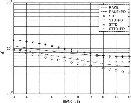
In figure 3 it is shown the performance results for 12 interfering users. As can be seen the use of PD filter, alone or combined with any of the proposed TD techniques reaches a performance improvement over the corresponding schemes without PD. This is done without any complexity cost at the MS and even the complexity at the BS is very
low. This happens because the proposed pre-distortion filter only takes into account the spreading sequences of the different active users, being calculated only once, kept in memory, and used the same impulse response of the filter as long as the active users present are kept unchanged. The scheme that achieves the best overall performance is the combination of STD with the PD filter. While the PD avoids the MAI with a reduction in the cross-correlation seen by the reference MS, the STD provides an additional gain due to the transmit diversity, thus, allowing the receiver to select the antenna that presents lower fading. When we compare the performances achieved with STD and STTD, for the considered propagation environment, we find two opposite conclusions: on the one side, when we consider the scheme without PD, the STTD reaches better performance. On the other side, if we consider the PD together, the STD is the TD technique that reaches better performance. This situation can be inverted depending on the propagation environment considered because the STD should outperform STTD for the single-path channel profile, while STTD should outperform STD for a channel profile closer to the uniform power profile [4]. As the considered propagation environment is closer to one or the other limit models the TD that must be chosen varies. When we compare the use of the STTD+PD with the RAKE+PD we find out that the latter reaches the best results. This can happen because RAKE receiver already takes advantage of the multipath environment to provide a kind of diversity, being this performance improvement higher than the one achieved with the use of the Space Time Codes, i.e., with the space-time transmit diversity.
In figure 4 it is shown that, for 6 interfering users, the PD filter tends to introduce a gain only for higher levels of
0
/
b
E N.
Additionally, when we compare the two kinds of TD diversities, we can observe that the STD achieves, in both cases (with and without PD) the best performance.
3 4 5 6 7 8 9 10 11 12 10-2 10-1 100 Eb/N0 (dB) Pe RAKE RAKE+PD STD STD+PD STTD STTD+PD
3 4 5 6 7 8 9 10 11 12 10-3 10-2 10-1 100 Eb/N0 (dB) Pe RAKE RAKE+PD STD STD+PD STTD STTD+PD
Figure 4 - BER performance for QPSK with 6 interfering users
Figure 5 presents the results with 3 interfering users. The results obtained are similar to those obtained for 6 interfering users.
3 4 5 6 7 8 9 10 11 12 10-3 10-2 10-1 100 Eb/N0 (dB) Pe RAKE RAKE+PD STD STD+PD STTD STTD+PD
Figure 5 - BER performance for QPSK with 3 interfering users
When we compare the gain achieved with the PD filter, for different number of users, we find out that this gain increases as the number of interfering users increase. It makes sense because the proposed PD filter considers the MV algorithm and therefore it is not precise, increasing the performance as the number of interfering users increase. For lower number of users the predominant kind of interference is the fading, while for higher number of users the system becomes MAI dependent. For lower number of users the RAKE receiver takes advantage of the multipath environment to provide a kind of diversity, combating the fading effectively. When the number of users is higher, the best approach to improve the performance consists in combating the MAI, and hence, the PD seems to provide best results. For all that has been exposed, with the use of the proposed PD filter the performance of the network becomes less dependent of the number of users active in the cell.
IV. CONCLUSIONS
In this document we have presented a combined scheme to combat MAI and fading, which is a power and bandwidth-efficient technique for the Rayleigh fading channel. Two specific schemes, namely, the PD scheme and two different types of TD (STD and STTD) were introduced and combined. The BER was taken as a figure of merit.
It was shown that the use of the proposed PD filter, alone or combined with any of the proposed TD techniques tends to reach a performance improvement over the corresponding schemes without PD. This is done without any complexity cost at the MS and even the complexity at the BS is very low because this pre-distortion filter only takes into account the spreading sequences of the different active users, being calculated only once, kept in memory, and used always the same impulse response of the filter as long as the active users present are kept unchanged.
In the current paper it was shown that the performance improvements of the PD filter increases as the number of interfering users increase. This happens because for lower number of users the predominant kind of interference is the fading, while for higher number of users the system becomes MAI dependent, being, in this situation, the PD filter the determinant tool to increase the performance.
With the use of the proposed PD filter, the decrease of performance observed with the increase in the number of users is lower than the decrease of performance achieved when the PD filter is not considered. For this reason, with the use of the PD filter the performance of the network becomes less dependent of the number of active users present in the cell.
When we consider the use of TD we can see that, for the Pedestrian A propagation environment of 3GPP the STD achieves the best performance.
For higher number of users, the best performance is achieved with a combination of the PD filter with a specified TD technique. This happens because with the combination of both schemes, on the one side, the system is cleaner of MAI, once the orthogonality between the signals seen by the different users can be improved (PD filter) and, on the other side, the TD combats the fading.
V. REFERENCES
[1] Mário M. Silva, Américo Correia, “Joint Multi-User Detection and Intersymbol Interference Cancellation for WCDMA Satellite UMTS”, Internation Jounal of Satellite Communications and Networking – Special Issue on Interference Cancellation – John Willey and Sons, Ltd, n.º 21/2003, pp. 93-117;
[2] Mário M. Silva., Américo Correia, “MAI Cancellation with Commutation Signaling”, Proc. of IEEE VTC’00, Tokyo, Japan, Spring 2000;
[3] Jinho Choi, “Interference Mitigation Using Transmitter Filters in CDMA Systems”, IEEE Transactions on Vehicular Technology, nº4-Vol.51, July 2002, pp. 657-666;
[4] Mário M. Silva, Américo Correia, “Combined Transmit Diversity and Beamforming for WCDMA”, Proc. of IEEE EPMCC’03, Glasgow, Scotland, April 2003;
[5] Américo Correia, “Optimised Complex Constellations for Transmission Diversity”, Wireless Personal Communications 20, March 2002, Journal of Kluwer Academic Pub, pp. 267-284;
[6] Mário M. Silva, Américo Correia, “Space Time Diversity for the Downlink of WCDMA”, Proc. of IEEE WPMC’01, Aalborg, Denmark, September 2001;
[7] Mário M. Silva, Américo Correia, “Space Time Block Coding for 4 antennas with coding rate 1”, Proc. of IEEE ISSSTA’02, Prague, Check Republic, Sep. 2002, pp. 318-322;
[8] Mário M. Silva, Américo Correia, “Space Time Coding Schemes for 4 or more Antennas”, Proc. of IEEE PIMRC’02, Lisbon, Portugal, Sep. 2002;