IB-DFE Receiver Techniques for CP-Assisted Block
Transmission within DS-CDMA and MC-CDMA
Systems
Rui Dinis, Paulo Silva and Ant´onio Gusm˜ao
CAPS-IST, Tech. Univ. of Lisbon, Av. Rovisco Pais, 1049-001 Lisboa, Portugal,
Phone: +351 218419358; Fax: +351 218465303; email: [email protected]
Abstract - MC-CDMA (MultiCarrier Code Division Multiple Access), currently regarded as a promissing multiple access scheme for broadband communications, is known to combine the advantages of an OFDM-based (Or-thogonal Frequency Division Multiplexing), CP-assisted (Cyclic Prefix) block transmission with those of CDMA systems. Recently, it was recognised that DS-CDMA (Di-rect Sequence) implementations can also take advantage of the beneficts of the CP-assisted block transmission approach, therefore enabling an efficient use of FFT-based (Fast Fourier Transform), chip level FDE (Frequency-Domain Equalisation) techniques.
In this paper we consider the use of IB-DFE (Iter-ative Block Decision Feedback Equalisation) FDE tech-niques within both CP-assisted MC-CDMA systems with frequency-domain spreading and DS-CDMA systems. Our simulation results show that an IB-DFE receiver with moderate complexity is suitable in both cases, with ex-cellent performances that can be close to the single-code matched filter bound (especially for the CP-assisted DS-CDMA alternative), even with full code usage.
I. Introduction
It is widely known that a CP-assisted block transmission approach, allowing low-complexity FDE receiver techniques, is suitable for high data rate transmission over severely time-dispersive channels. This approach can be employed with ei-ther MC (MultiCarrier) or SC (Single-Carrier) modulations [1], [2]. When adopted in CDMA systems, it leads to MC-CDMA implementations [3], [4], [5], and also, as recently recognized, quite efficient DS-CDMA implementations [6]. These CP-assisted schemes are especially interesting for multicode and/or downlink transmission, since all codes are synchronised, which simplifies the receiver implementation.
Conventional, linear FDE techniques are known to lead to a significant noise enhancement when a ZF (Zero Forcing) criterion is adopted in channels with deep in-band notches, which can lead to significant performance degradation. For this reason, an MMSE (Minimum Mean-Squared Error) FDE equaliser is usually preferable [7]. However, an MMSE FDE does not perform an ideal channel inversion. Therefore, when this type of equaliser is employed within CP-assisted CDMA
systems, we are not able to fully orthogonalise the different spreading codes. This means severe interference levels, espe-cially when different powers are assigned to different codes.
It is well-known that nonlinear equalisers can significantly outperform linear equalisers. For this reason, a promising IB-DFE (Iterative Block Decision Feedback Equalisation) ap-proach proposed for CP-assisted SC schemes [8], with both the feedforward and the feedback parts implemented in the frequency domain (a similar concept was also proposed in [9]). Since the feedback loop takes into account not just the hard-decisions for each block, but also the overall block reliability, the error propagation problem is significantly re-duced. Consequently, the IB-DFE receivers offer much better performances than the linear, non-iterative FDE receivers [8], [10]; moreover, their implementation is much less complex than that of frequency-domain turbo-equalisation [11].
In this paper, we consider the use of IB-DFE techniques for CP-assisted block transmission within MC-CDMA systems with frequency-domain spreading and DS-CDMA systems.
This paper is organized as follows: Sec. II describes the CP-assisted CDMA schemes. The IB-DFE receiver is described in sec. III. A set of performance results is presented in sec. IV, and sec. V is concerned with the conclusions and complementary remarks of this paper.
II. CP-Assisted CDMA Schemes
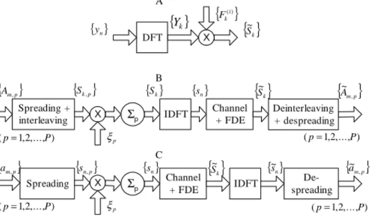
In this section we describe the CP-assisted DS-CDMA and MC-CDMA schemes to be considered, involving a multicode transmission with constant spreading factor (the extension to VSF schemes (Variable Spreading Factor) is straightforward). In both cases, the receiver can be based on a linear FDE, as depicted in fig. 1A. As with other CP-assisted techniques, after removing the cyclic extension, the received time-domain block fyn; n = 0; 1; : : : ; N ¡ 1g is passed to the frequency domain, leading to the blockfYk; k = 0; 1; : : : ; N ¡ 1g. When the cyclic extension is longer than the overall channel impulse response, the samplesYk can be written as
Yk= HkSk+ Nk; (1)
where Hk and Nk denote the channel frequency response and the noise term for the kth frequency, respectively, and fSk; k = 0; 1; : : : ; N ¡ 1g = DFT fsn; n = 0; 1; : : : ; N ¡ 1g,
withfsn; n = 0; 1; : : : ; N ¡ 1g denoting the transmitted time-domain block. For a linear FDE, fhe frequency-time-domain samples at its output are given by
~
Sk = FkYk; (2)
wherefFk; k = 0; 1; : : : ; N ¡ 1g denote the FDE coefficients. If these coefficients are optimised under the MMSE criterion (Minimum Mean Squared Error), then
Fk= H
¤ k
® + jHkj2; (3)
where® = ¾2n=¾2s, with ¾n2 and¾s2 denoting the variance of the noise and data symbols, respectively.
A. MC-CDMA
The frequency-domain block to be transmitted is fSk; k = 0; 1; : : : ; N ¡ 1g, where N = KM, with K denoting the spreading factor and M the number of data symbols per spreading code. The frequency-domain symbols are given by Sk = PPp=1»pSk;p, where »p is an appropriate weighting coefficient for power control purposes (the power associated to the pth spreading code is proportional to »p2). fSk;p; k = 0; 1; : : : ; N ¡ 1g is an interleaved version of fS0
k;p; k = 0; 1; : : : ; N ¡ 1g (rectangular K £ M interleaver, so that different chips associated with a given data symbol are spaced byM subcarriers).
S0
k;p= Ck;pAbk=Kc;p (4)
is thekth chip for the pth spreading code (bxc denotes ’larger integer not higher that x’). fAm;p; m = 0; 1; : : : ; M ¡ 1g denotes the block of data symbols associated to the pth spreading code and fCk;p; k = 0; 1; : : : ; N ¡ 1g is the corresponding spreading sequence. An orthogonal spreading is assumed throughout this paper, with Ck;p belonging to a QPSK constellation (Quaternary Phase Shift Keying). Without loss of generality, it is assumed thatjCk;pj = 1. At the receiver side, theAk;p coefficients are estimated from
~ Am;p = X k02ªm ~ Sk0Ck¤0;p; (5)
withªm = fm; m + M; : : : ; m + (K ¡ 1)Mg denoting the set of frequencies employed to transmit the mth data symbol of each spreading code and ~Sk given by (2).
B. DS-CDMA
Let us consider now a DS-CDMA scheme. The transmitted block of chips isfsn; n = 0; 1; : : : ; N ¡1g, where N = KM, with K denoting the spreading factor and M denoting the number of data symbols for each user. The overall ”chip” symbolssn are given by sn =Pp=1P »psn;p, where »p is an weighting coefficient, proportional to the transmitted power for thepth user, and
sn;p= cn;pabn=Kc;p (6)
is the nth chip for the pth user. fam; m = 0; 1; : : : ; M ¡ 1g denotes the block of data symbols associated to thepth user and fcn;p; n = 0; 1; : : : ; N ¡ 1g denotes the corresponding spread-ing sequence. As with MC-CDMA, an orthogonal spreadspread-ing andjcn;pj = 1 are also assumed.
In this case, the FDE receiver could estimate the data symbols from ~am;p = mK+K¡1X n0=mK ~sn0c¤n0;p; (7) withf~sn; n = 0; 1; : : : ; N ¡1g = IDFT f ~Sk; k = 0; 1; : : : ; N ¡ 1g (see fig. 1C). X { }Yk
{ }
) (i k F DFT{ }
sn,p{ }
Sk ~{ }
am,p Channel + FDE{ }
Sk ~ IDFT{ }
a~m,p De-spreading { }s~n { }sn Spreading + interleaving{ }
Am,p Channel + FDE{ }
Sk ~ IDFT{ }
Am,p ~ Deinterleaving + despreading{ }
Sk,p { }yn A B C { }Sk X p ξ Σp ) ,..., 2 , 1 (p= P (p=1,2,...,P) Spreading X p ξ Σp ) ,..., 2 , 1 (p= P (p=1,2,...,P) { }snFig. 1. FDE structure (A) and transmission models for MC-CDMA (B) and
DS-CDMA (C).
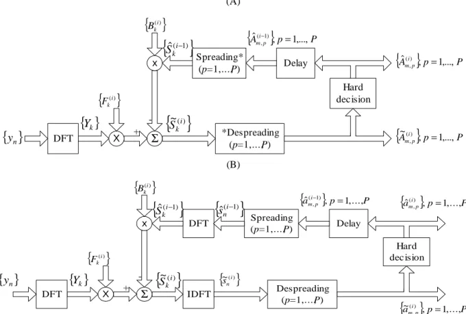
III. Iterative Block Decision Feedback Equalization for Prefix-Assisted CDMA
Fig. 2 presents the receiver structures that we are considering in this paper, where the linear FDE is replaced by an IB-DFE. In both cases, for a given iteration i, the output samples are given by
~
Sk(i)= Fk(i)Yk¡ Bk(i)S^k(i¡1) (8) where fFk(l;i); k = 0; 1; : : : ; N ¡ 1g (l = 1; 2; : : : ; L) and fBk(i); k = 0; 1; : : : ; N ¡ 1g denote the feedforward and the feedback coefficients, respectively. The block f ^Sk(i¡1); k = 0; 1; : : : ; N ¡ 1g is an etimate of the transmitted block fSk(i¡1); k = 0; 1; : : : ; N¡1g, obtained form the data estimates of the(i ¡ 1)th iteration.
It can be shown that the optimum feedback and feedforward coefficients are given by
Bk(i)= ½(i¡1)³F(i)
k Hk¡ °(i) ´ (9) and Fk(i)= Hk¤ ® + (1 ¡ (½(i¡1))2)jHkj2; (10) respectively, where °(i)= 1 N N¡1X k=0 Fk(i)Hk: (11)
(A) X
{ }
Y
k{ }
(i) k F DFT{ }
y
n x{ }
(i) k BΣ
Hard decision{ }
Amip ,p 1,...,P ~() , ={ }
~
(i) kS
{ }
Ai p P p m , 1,..., ˆ() , ={ }
ˆ
(i−1) kS
+ Delay{ }
Ai p P p m , 1,..., ˆ( 1) , = − Spreading* (p=1,...,P) *Despreading (p=1,...,P) (B) X{ }
Y
k{ }
(i) k F DFT{ }
y
n x{ }
(i) k BΣ
Hard dec ision{ }
a i p P p m , 1,..., ~() , = IDFT{ }
~
(i) kS
DFT{ }
ai p P p m , 1,..., ˆ() , ={ }
ˆ
(i−1) kS
+ Delay{ }
ai p P p m , 1,..., ˆ( 1) , = − Spreading (p=1,...,P){ }
( 1)ˆ
ni−s
Despreading (p=1,...,P){ }
~(i) n sFig. 2. IB-DFE receiver for MC-CDMA (A) (* denotes the complementary interleaving/deinterleaving) and DS-CDMA (B).
The coefficient½(i¡1), which can be regarded as the block-wise reliability of the decisions used in the feedback loop (from the previous iteration), is given by
½(i¡1)= E[ ^S(i¡1)
k Sk¤]=E[jSkj2]: (12) This correlation factor is crucial for the good performance of the proposed receivers. Assuming uncorrelated data blocks, it can be easily shown that
½(i¡1)=XP p=1 »2 p½(i¡1)p ; (13) with ½(i¡1) p = E[ ^Ak;pA¤k;p] E[jAk;pj2] = E[^an;pa¤n;p] E[jan;pj2] : (14) Clearly, for the first iteration (i = 0), no information exists about Sk and the correlation coefficient is zero; therefore, Bk(0) = 0 and Fk(0) equals the right-hand side of (3). After that first iteration, and if the residual BER is not too high (at least for the spreading codes with higher transmit power), we can use the feedback coefficients to eliminate a significant part of the residual interference. When ½ ¼ 1 (after several iterations and/or moderate-to-high SNRs), we have an almost full cancellation of the ”inter-code” interference through these coefficients, while the feedforward coefficients perform an approximate matched filtering.
IV. Performance Results
In this section we present a set of performance results concerning the proposed receiver structure. We consider the downlink transmission, with each spreading code intended to a given user. It is assumed thatN = K = 256 (similar results could be obtained for other values ofN) and the data symbols are selected from a QPSK constellation under a Gray mapping rule. For both DS-CDMA and MC-CDMA, we considered an orthogonal spreading (Hadamard-Walsh sequences plus pseudo-random scrambling sequences with the same chip rate) and the power amplifier at the transmitter is assumed to be linear. We consider a channel characterized by the power delay profile type C for the HIPERLAN/2 (HIgh PERformance Local Area Network) [13], with uncorrelated Rayleigh fading on the different paths. The subcarrier separation is 0.2MHz. Perfect synchronisation and channel estimation are assumed in all cases. The number of users isK, i.e., we are assuming a fully loaded system. For the sake of comparisons, we included the MFB performance (Matched Filter Bound).
Figs. 3 and 4 concern MC-CDMA and DS-CDMA schemes, respectively. Clearly, the iterative procedure allows a signifi-cant improvement relatively to the conventional linear FDE (first iteration). Moreover, the achievable performances are close to the MFB after three iterations. It was also observed that the performances are very similar, slightly better for DS-CDMA.
0 5 10 15 10−4 10−3 10−2 10−1 E b/N0(dB) BER _____ : Iter 1 − − − − : Iter. 2 − ⋅ − ⋅ : Iter. 3 ⋅⋅⋅⋅ : MFB
Fig. 3. MC-CDMA BER performance whenK = 256 (M = 1) and
P = 256 users, with the same assigned power.
0 5 10 15 10−4 10−3 10−2 10−1 100 Eb/N0(dB) BER ____ : Iter. 1 − − − : Iter. 2 − ⋅ − : Iter. 3 ⋅⋅⋅ : MFB
Fig. 4. DS-CDMA BER performance whenK = 256 (M = 1) and P =
256 users, with the same assigned power.
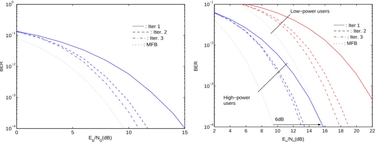
Let us consider now that the power assigned toK=2 = 128 users is 6dB below the power assigned to the otherK=2 = 128 users. Clearly, the low-power users face strong interference levels. Figs. 5 and 6 present the BER performances, expressed as a function of the Eb=N0 of high-power users, 6dB below the Eb=N0 of low-power users). Once again, the iterative receiver allows significant performance improvements. From these figures, it is clear that gains associated to the performance of the iterative procedure are higher for low-power users and the BERs are closer to the MFB than for the high-power users. Moreover, the performances of high-power users are still a few dB from the MFB after three iterations, especially for the MC-CDMA schemes. This is explained as follows: the BER is much lower for high-power users, allowing an
2 4 6 8 10 12 14 16 18 20 22 10−4 10−3 10−2 Eb/N0(dB) BER _____ : Iter 1 − − − − : Iter. 2 − ⋅ − ⋅ : Iter. 3 ⋅⋅⋅⋅ : MFB Low−power users High−power users 6dB
Fig. 5. MC-CDMA BER performance withK=2 = 128 low-power users
andK=2 = 128 high-power users.
0 5 10 15 20 25 10−4 10−3 10−2 10−1 100 Eb/N0(dB) BER ____ : Iter. 1 − − − : Iter. 2 − ⋅ − : Iter. 3 ⋅⋅⋅ : MFB High−power users Low−power users 6dB
Fig. 6. DS-CDMA BER performance with K=2 = 128 low-power users
andK=2 = 128 high-power users.
almost perfect interference cancelation of their effects on low-power users; the higher BERs for the low-low-power users preclude an appropriate interference cancelation when we detect high-power users, where the BERs are expressed as a function of theEb=N0of high-power users, 6dB below theEb=N0of low-power users). Once again, the MC-CDMA schemes have worse performances than the DS-CDMA schemes.
V. Conclusions and Complementary Remarks In this paper we considered the use of IB-DFE techniques for multicode CP-assisted DS-CDMA and MC-CDMA systems. The proposed receiver has excellent performance, that can be close to the MFB performance, especially for DS-CDMA schemes.
0 5 10 15 10−4 10−3 10−2 10−1 100 Eb/N0(dB) BER − − − : DS−CDMA ____ : MC−CDMA ⋅⋅⋅ : MFB Iter. 1 2 3
Fig. 7. BER performances for a Fourier spreading (with no scrambling),
whenN = K = 256 and P = 256 spreading codes, with the same assigned
power.
It should be noted that the type of spreading adopted can have a significant impact on the performance of CP-assisted CDMA schemes. As an extreme example (see Fig. 7), forM = 1, full code usage under equal power conditions and a Fourier spreading/despreading with no complementary scrambling, the MC-CDMA scheme considered in this paper is equivalent to a CP-assisted SC scheme [12], and our receiver reduces to the IB-DFE receiver described in [8], [10]. On the other hand, for M = 1, full code usage under equal power conditions and a Fourier spreading/despreading with no complementary scrambling, the DS-CDMA scheme considered in this paper is equivalent to an OFDM scheme (then there is no advantage in using the IB-DFE receiver).
It should also be noted that, for K < N, the performances of MC-CDMA schemes are worse since just a fraction 1=M of the frequencies is used for the transmission of a given data symbol. This is not the case of DS-CDMA, where all frequencies can be used for transmitting each data symbol, regardless of the spreading factor. However, it should be noted that this does not mean necessarily an weakness of the MC-CDMA schemes with small spreading factors (smallK). The comparison between DS-CDMA and MC-CDMA schemes should take into account other aspects, such as the envelope fluctuations of the transmitted signals and the impact of the channel coding (one might expect larger coding gains for MC-CDMA schemes, especially when a smallK is combined with interburst interleaving).
Acknowledgment
This work was partially supported by the FCT project POSI/CPS/46701/2002 - MC-CDMA.
References
[1] L.Cimini Jr., “Analysis and Simulation of a Digital Mobile Channel using Orthogonal Frequency Division Multiplexing”,
IEEE Trans. on Comm., Vol. 33, No. 7, July 1985.
[2] H.Sari, G.Karam and I.Jeanclaude, ”An Analysis of Orthogonal Frequency-division Multiplexing for Mobile Radio Applications”,
In Proc. IEEE Vehic. Tech. Conf., VTC’94, pp. 1635–1639,
Stockholm, June 1994.
[3] S. Hara and R. Prasad, “Overview of Multicarrier CDMA”, IEEE
Comm. Magazine, Dec. 1997.
[4] S. Hara and R. Prasad, “Design and Performance of Multicarrier CDMA System in Frequency-Selective Rayleigh Fading Chan-nels”, IEEE Trans. on Vehicular Technology, Vol. 48, No. 5, Sep. 1999.
[5] H. Sari, “Orthogonal Multicarrier CDMA and its Detection on Frequency-Selective Channels”, European Trans. on Telecomm., Vol. 13, No. 5, pp. 439–445, Sep.–Oct. 2002.
[6] K. Baum, T. Thomas, F. Vook, V. Nangia, “Cyclic-Prefix CDMA: An Improved Transmission Method for Broadband DS-CDMA Cellular Systems”, IEEE WCNC, pp. 183–188, 2002.
[7] A.Gusm˜ao, R.Dinis and N.Esteves, “On Frequency-domain Equalization and Diversity Combining for Broadband Wireless Communications”, IEEE Trans. on Comm., Vol. 51, No. 7, pp. 1029–1033, July 2003.
[8] N. Benvenuto and S. Tomasin, “Block Iterative DFE for Single Carrier Modulation”, IEE Elec. Let., Vol. 39, No. 19, pp. 1144– 1145, Sep. 2002.
[9] M. Reinhardt and J. Lindner, “Transformation of a Rayleigh Fading Channel into a Set of Parallel AWGN Channels and its Advantage for Coded Transmission”, IEE Elect. Letters, Vol. 31, No. 25, pp. 2154–2155, Dec. 1995.
[10] R. Dinis, A. Gusm˜ao, and N. Esteves, “On Broadband Block Transmission over Strongly Frequency-Selective Fading Chan-nels”, Proc. Wireless 2003, Calgary, Canada, July 2003. [11] M. T ¨uchler, R. Koetter and A. Singer, “Turbo Equalization:
Principles and New Results”, IEEE Trans. on Comm., Vol. 50, May 2002.
[12] K. Br¨uninghaus and H. Rohling, “Multi-carrier Spread Spec-trum and its Relationship to Single-carrier Transmission”, IEEE
VTC’98, May 1998.
[13] ETSI, “Channel models for HIPERLAN/2 in Different Indoor Scenarios”, ETSI EP BRAN 3ERI085B, pp. 1-8, March 1998.