Universidade de Aveiro 2017
Departamento de Química
Daniel Martins
Cordeiro
Desenvolvimento de membranas compósitas à base
de celulose bacteriana para pilhas de combustível
microbianas
Universidade de Aveiro 2017
Departamento de Química
Daniel Martins
Cordeiro
Desenvolvimento de membranas compósitas à base
de celulose bacteriana para pilhas de combustível
microbianas
Tese apresentada à Universidade de Aveiro para cumprimento dos requisitos necessários à obtenção do grau de Mestre em Biotecnologia, ramo Industrial e Ambiental, realizada sob a orientação científica da Doutora Carla Andreia Cunha Vilela, Investigadora de Pós-Doutoramento do CICECO – Instituto de Materiais de Aveiro e do Departamento de Química da Universidade de Aveiro e da Doutora Carmen Sofia da Rocha Freire Barros, Investigadora Principal do CICECO – Instituto de Materiais de Aveiro e do Departamento de Química da Universidade de Aveiro.
Dedicar este trabalho à entidade, qualquer que ela seja, que permite que após 400 anos de método científico, e com milhões de cientistas a investigar nos entretantos, ainda existam temas novos nos quais trabalhar. E que assim continue!
E, como não podia deixar de ser, aos meus pais, investidores a fundo perdido por excelência.
o júri
Presidente Professora Doutora Luísa Alexandra Seuanes Serafim Martins Leal
Professora Auxiliar da Universidade de Aveiro
Doutor Filipe Miguel Henriques Lebre Ramos Figueiredo
Investigador Principal da Universidade de Aveiro
Doutora Carla Andreia Cunha Vilela
agradecimentos Agradecer às minhas orientadoras Carla Vilela e Carmen Freire pelo acompanhamento, paciência e estímulo à autonomia.
À Paula Barbosa pela ajuda com as medidas de condutividade protónica. Ao Ricardo Pinto pela ajuda com a microscopia eletrónica de varrimento. Ao CICECO – Instituto de Materiais do Departamento de Química e da Universidade de Aveiro pelo apoio material e disponibilização do laboratório. À professora Alexandra Rodrigues Pinto e à Joana Vila Boas do Departamento de Engenharia Química da FEUP – Faculdade de Engenharia da Universidade do Porto pela parceria e realização dos testes em pilhas de combustível microbianas.
palavras-chave Celulose bacteriana, ácido poli(estireno sulfónico), compósitos de matriz polimérica, membranas de permuta protónica, pilhas de combustível microbianas.
resumo As pilhas de combustível microbianas constituem uma tecnologia com a potencialidade de produção de energia elétrica com simultâneo tratamento de efluentes. Esta potencialidade assume particular relevância num mundo que cada vez mais procura soluções ecológicas e sustentáveis para a produção de eletricidade. Neste sentido, o desenvolvimento de membranas de permuta protónica com base em celulose bacteriana (BC) irá contribuir para aumentar o caráter ecológico das pilhas de combustível microbianas (MFCs). O presente trabalho tem por objetivo o desenvolvimento de membranas compósitas baseadas em BC e no ácido poli(4-estireno sulfónico) (PSSA) para aplicação em MFCs. Deste modo, a produção, caraterização e aplicação de membranas de PSSA/BC numa pilha de combustível microbiana é descrita como uma abordagem relevante à produção de eletricidade por microrganismos com recurso a materiais de base biológica. O polímero PSSA foi incorporado com sucesso na estrutura tridimensional da BC através da polimerização radicalar
in situ do monómero ácido 4-estirenosulfónico na presença de um agente reticulante. Estas membranas compósitas apresentam uma capacidade de troca iónica de 1,85 ± 0,83 mmol.g-1 e condutividades protónicas máximas de 17,3 mS.cm-1 (94 ºC, 98% humidade relativa, configuração através-do-plano) e 344 mS.cm-1 (80 ºC, 98% humidade relativa, configuração em-plano). Estes resultados demonstram um comportamento anisotrópico da condutividade protónica das membranas compósitas dependente da configuração em que é medida. A aplicação de uma membrana de PSSA/BC numa pilha de combustível microbiana originou uma potencia máxima de 2,42 mW.m-2, uma voltagem de circuito aberto de 0,436 V e uma resistência interna de 1,51×10⁴ Ω. Estes valores são superiores aos obtidos com uma membrana comercial de Nafion®.
keywords Bacterial cellulose, poly(styrene sulfonic acid), polymer matrix composites, proton exchange membranes, microbial fuel cells.
abstract Microbial fuel cells are a technology with the potentiality to be used on the production of electricity while simultaneously treating effluents. This potentiality is particularly relevant in a world that actively searches for ecological and sustainable solutions for electricity production. In this sense, the development of proton exchange membranes based on bacterial cellulose (BC) can contribute to increase the ecological character of microbial fuel cells (MFCs). The present work has the objective of developing nanocomposite membranes based on BC and poly(4-styrene sulfonic acid) (PSSA) for application on MFCs. As such, the production, characterization and application of PSSA/BC membranes in a MFC is described as a relevant approach on the production of electricity by microorganisms and with the resort to bio-based materials. The PSSA polymer was successfully incorporated into the BC three-dimensional structure by the in situ free radical polymerization of the 4-styrene sulfonic acid monomer in the presence of a cross-linking agent. This nanocomposite membrane shows an ionic exchange capacity of 1.85 ± 0.83 mmol.g-1 and maximum protonic conductivities of 17.3 mS.cm-1 (94 ºC, 98% relative humidity (RH), through-plane configuration) and 344 mS.cm-1 (80 ºC, 98% RH, in-plane configuration). These results show a nanocomposite membrane with anisotropic proton conductance behaviour dependant on the configuration in which the protonic conductivity is measured. The PSSA/BC application on a single-chamber MFC yielded a maximum power density of 2.42 mW.m-2, an open circuit voltage of 0.436 V and an internal resistance of 1.51×10⁴ Ω. These results are superior than those obtained with a commercial Nafion® membrane.
Outline
1. Introduction ... 1
1.1. The Context ... 1
1.2. Conventional fuel cells ... 2
1.2.1. Proton exchange fuel cells... 2
1.2.2. Alkaline fuel cells... 4
1.2.3. Direct methanol fuel cells ... 4
1.2.4. Phosphoric acid fuel cells ... 5
1.2.5. Molten carbonate fuel cells ... 5
1.2.6. Solid oxide fuel cells ... 6
1.3. Microbial fuel cells ... 7
1.3.2. Design and components ... 7
1.3.2.1. Anode ... 8
1.3.2.2. Cathode ... 8
1.3.2.3. Proton exchange membrane ... 9
1.3.3. Microorganisms used in MFC ... 10
1.3.3.1. Bioelectrogenesis ... 10
1.3.3.2. Anodic electron transfer ... 11
1.3.3.3. Microbial communities in MFC ... 13 1.3.4. Operational parameters ... 14 1.3.4.1. Temperature ... 14 1.3.4.2. pH ... 14 1.3.4.3. Organic substrate ... 15 1.3.5. MFC applications ... 15 1.3.6. Limitations of MFC performance ... 16
1.4. Proton exchange membranes ... 17
1.4.2. Proton conducting mechanisms ... 17
1.4.3. PEM matrix polymers ... 19
1.4.3.1. Fluorinated polymers ... 19 1.4.3.2. Non-fluorinated polymers ... 19 1.5. Bacterial cellulose ... 20 1.5.1. BC production ... 23 1.5.2. BC properties... 25 1.5.3. BC modification ... 25 1.5.4. BC applications ... 26
1.5.4.1. Food applications ... 26
1.5.4.2. Medical applications ... 27
1.5.4.3. Other applications ... 27
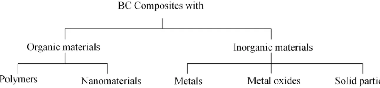
1.5.5. BC-based composites ... 27
1.5.5.1. BC-based composites for electronic/conductive purposes... 28
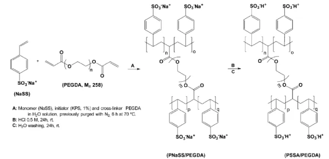
1.5.6. PSSA/BC nanocomposite membranes ... 31
1.6. Objectives ... 32
2. Experimental section ... 33
2.1. Materials and reagents ... 33
2.2. BC membrane production ... 33
2.3. PSSA/BC composite membrane preparation ... 34
2.4. PSSA/BC membrane characterization ... 34
2.4.1. FTIR-ATR spectroscopy ... 34
2.4.2. Scanning electronic microscopy... 35
2.4.3. Ionic exchange capacity (IEC) ... 35
2.4.4. Protonic conductivity ... 35
2.5 Membrane application on microbial fuel cell ... 36
3. Results and Discussion ... 39
3.1. PSSA/BC membrane characterization ... 39
3.1.1 FTIR-ATR spectroscopy ... 39
3.1.2. Scanning electronic microscopy... 42
3.1.3. Ionic exchange capacity ... 43
3.1.4. Protonic conductivity ... 44
3.2. PSSA/BC membrane application on microbial fuel cell ... 47
4. Conclusions ... 51
5. References... 52
Figures
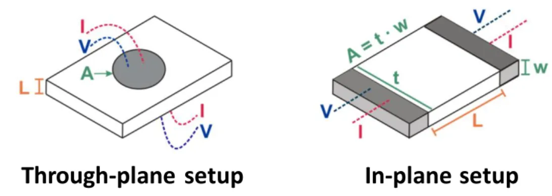
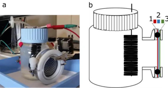
Figure 1 – General scheme of a PEMFC. Adapted from Larminie & Dicks, 2001……….3 Figure 2 – General configurations of a double-chamber MFC, and single-chamber MFC. Adapted from Leong et al., 2013……….……….…...……….……….8 Figure 3 – Transference of electrons from bacteria to the anode can be performed directly, by DET (through membrane proteins or nanowires), or indirectly, by MET (through chemical mediators). Adapted from Rahimnejad et al., 2015. ……….………...……….………...12 Figure 4 – Proton vehicular and hopping mechanisms in a hydrated PFSI membrane. Adapted from Kim et al., 2015. ……….……….………....……….19 Figure 5 – Cellulose polymer, highlighting the cellobiose unit between brackets, as well as the non-reducing and non-reducing end groups. Adapted from Nechyporchuk et al., 2015. ……….…….…….21 Figure 6 – Schematized process of BC production. Adapted from Cacicedo et al., 2015. ………..22 Figure 7 – Hydrated BC membrane grown under static conditions.……….………..24 Figure 8 – Classes of materials used in BC-based composites. Adapted from Shah et al., 2013.…28 Figure 9 – PSSA polymerization scheme with PEGDA as a crosslinking agent, followed by acidic ionic exchange. Adapted from Gadim et al., 2014. ………...……….………..31 Figure 10 – Schematic representation of the setups of the proton conductivity measured via through-plane and in-plane configuration. Adapted from Gadim et al., 2017. ………36 Figure 11 – Assembled MFC and respective schematic highlighting the MEA. ……….………37 Figure 12 – Native BC membrane and PSSA/BC composite membrane, both after acidic treatment
and dried.…….…………...…….……….……….………39
Figure 13- FTIR spectra of a BC membrane, hydrated PSSA (PSSA: PEGDA of 1:0.1), and a PSSA/BC membrane.…….……….……….…...……….………..41
Figure 14 – Surface SEM micrographs of acid treated BC and PSSA/BC membranes. .….………..42 Figure 15 – Cross-section SEM micrographs of acid treated BC, and PSSA/BC membranes. …...43 Figure 16 – Protonic conductivity of selected PSSA/BC membrane measured in through-plane and in-plane disposition. ……….…...……….………...45 Figure 17 – Through-plane protonic conductivity of acid treated BC. Adapted from the supporting information of Gadim et al., 2014. ………..……….………... 46
Figure 18 – First and second polarization curves, and first and second power density curves for membranes of BC, Nafion® and PSSA/BC……….………. 49
Tables
Table 1 – Single-chamber MFC components and description………...…….………37 Table 2 – Through-plane protonic conductivity. …………..…….…...………47 Table 3 – In-plane protonic conductivity. …………...……….……….47
Abbreviations
AEM Anion exchange membrane AFC Alkaline fuel cell
ATP Adenosine triphosphate BC Bacterial cellulose CFU Colony forming units COD Chemical oxygen demand DET Direct electron transfer DFFC Direct fuelled fuel cell DMFC Direct methanol fuel cell FAD+ Flavin adenine dinucleotide FMN+ Flavin mononucleotide
FTIR-ATR Fourier transform infrared-attenuated total reflectance GRAS Generally recognized as safe
Hap Hydroxyapatite HS Hestrin-Schramm KPS Potassium persulfate IEC Ionic exchange capacity IS Impedance spectroscopy MCFC Molten carbonate fuel cell MEA Membrane-electrode assembly
MET Mediated electron transfer MFC Microbial fuel cell
MOEP Methacryloyloxyethyl phosphate NAD+ Nicotinamide adenine dinucleotide NMMO N-methyl-morpholine N-oxide
NP Nanoparticles OCV Open-circuit voltage
OLED Organic light emitting diodes PAFC Phosphoric acid fuel cell
PAMPS Poly(2-acrylamido-2-methyl-1-propanesulphonic acid) PANI Polyaniline
PEM Proton exchange membrane
PEMFC Proton exchange membrane fuel cell PFSI Perfluorosulphonic ionomer
PHEMA Poly(2-hydroxyethyl methacrylate) PMOEP Poly(methacryloyloxyethyl phosphate) PPy Polypyrrole
PSSA Poly(4-styrene sulphonic acid) PTFE Poly(tetrafluoroethylene) PVA Poly(vinyl alcohol) RH Relative humidity
SEM Scanning electronic microscopy UV Ultra violet
1. Introduction
1.1. The Context
In a technological society with an ever-increasing demand for energy, the efficiency with which different forms of storing energy are converted between each other is as relevant as the abundance of the primary sources of that same energy. In this context, the fuel cell technology supplies a generally more efficient way to convert energy stored in chemical compounds into a directly consumable energy, electricity, when compared with the widespread traditional technologies.
The availability of large quantities of unharnessed energetic potential in organic compounds further increased the scope of the fuel cell technology with the development of microbial fuel cells. These are devices that take advantage of the biocatalytic abilities of microorganisms to produce electricity from the microorganism-mediated oxidation of organic substrates. Simultaneously, the ecological and sustainable nature of microbial fuel cell operation and electricity production further increased the interest and potential of microbial fuel cells application.
However, one of the microbial fuel cell key components, the proton exchange membrane, is remarkable for its high costs, namely when made of perfluorosulphonic ionomers. As a more ecological alternative for proton exchange membrane production, bacterial cellulose-based composites were developed, with focus on the proton conducting properties of these composite materials. In this sense, two groups of composite materials were used, bacterial celluloses functionalized with phosphoric acid, described in the works of Gaopeng Jiang et al., 2012 and Vilela et al., 2016, and compounds functionalized with sulphonic groups, developed in the works of Gadim et al., 2014, 2015 and 2017 Gaopeng Jiang et al., 2015 and Lin et al, 2013.
The purpose of this work is to continue the study of the membranes developed by Gadim et al., 2014 by applying them as proton exchange membranes in microbial fuel cells. As such, in this work a broad theoretical framework of the fuel cell technology and on the subject of bacterial cellulose is provided, followed by the description of the preparation, characterization and, finally, application of poly(4-styrene sulfonic acid)/bacterial cellulose composite membranes on a microbial fuel cell.
1.2. Conventional fuel cells
Fuel cells are devices that perform the conversion of energy stored in chemical compounds into electric energy. Batteries and combustion engines are two alternative technologies to perform this conversion (Sharaf & Orhan, 2014). Combustion engines produce energy as work through oxidation by means of fuel combustion (e.g., fossil fuels); this energy is afterwards converted into electric energy by an electrical power generator. This multi-step conversion has low efficiencies, which are further limited by the theoretical Carnot efficiency. In addition, combustion engines produce noise, vibrations and pollutant gases, including greenhouse effect gases. In batteries, electric energy is produced typically by the oxidation of metallic electrodes, in a mild acid electrolyte, upon which exhaustion, batteries must be discarded or recharged, considering that the battery focus is on energy storage rather than energy conversion. Moreover, batteries are susceptible to deterioration and variations in energy output in different phases of their life cycle. On the other hand, fuel cells show some of the highest efficiencies in energy conversion, which is performed without noise and vibration. Depending upon the class of fuel cell, this conversion has the potentiality to originate only water and heat as reaction products. This is done by electrochemically oxidising fuels, which are directly converted into electrical energy. On the down side, the components and the assembly of fuel cells are expensive and their life cycle is relatively short, which is associated with a loss of efficiency with time, due to the degradation of essential components, such as the catalyst or electrolyte (Sharaf & Orhan,
2014). In general terms, conventional fuel cells are made up of three essential components:
the electrolyte, the fuel electrode (anode) and the air electrode (cathode); depending on the fuel cell type, these basic components may differ in construction, materials and design.
Six different main fuel cell classes are described, based on the nature of the electrolyte, namely, proton exchange membrane fuel cells (PEMFC), alkaline fuel cells (AFC), direct methanol fuel cells (DMFC), phosphoric acid fuel cells (PAFC), molten carbonate fuel cells (MCFC) and solid oxide fuel cells (SOFC) (Larminie & Dicks, 2001).
1.2.1. Proton exchange fuel cells
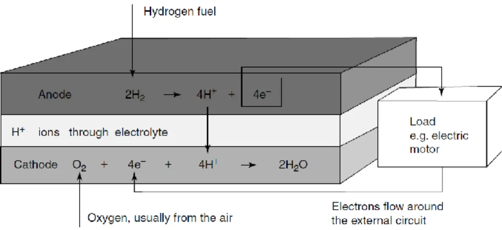
Proton exchange membranes fuel cells(PEMFC) are considered one of the most promising classes of fuel cells (Sharaf & Orhan, 2014; C. Wang, 2004). PEMFCs are characterized
by the presence of a polymer, often Nafion® (Haile, 2003), that guarantees permeability to protons, low electron conductivity and the physical separation between the fuel, hydrogen, present in the anode, and oxygen, present in the cathode; and a platinum (Pt)-based catalyst
(Y. Wang, Chen, Mishler, Cho, & Adroher, 2011). In PEMFCs hydrogen is supplied as
fuel to the anode chamber, where the platinum present in the anode splits hydrogen molecules into electrons, collected by the electrode, where they are conducted to the cathode chamber, originating energy as an electric flow; and protons, that permeate through the proton exchange membrane to the cathode chamber. In the cathode chamber, the electrons and the protons are combined with atmospheric O2, originating water and heat
as reaction products, and electricity (Haile, 2003; Sharaf & Orhan, 2014), as schematized in Figure 1. Due to its flexibility and scalability, PEMFCs are used in stationary, transportable and portable applications, meaning that PEMFC can function as large scale, hydrogen-based central power stations for electricity production, as powertrain for electric vehicles, such as buses, cars or motorcycles or as power supply to laptops and mobile phones (Y. Wang et al., 2011). Additionally, PEMFCs have low operating temperatures (60-80 ºC) (Sharaf & Orhan, 2014), high power densities, excellent dynamic characteristics, when compared with other fuel cells types (Y. Wang et al., 2011), are easy and safe to handle and have short start-up times (Sharaf & Orhan, 2014). On the down side, PEMFCs are expensive, mainly due to the platinum-based catalyst and to the proton exchange membrane-electrode assembly and have a low durability, due to a notable degradation and loss of efficiency of the proton exchange membrane (Sharaf & Orhan,
2014; Y. Wang et al., 2011).
1.2.2. Alkaline fuel cells
Alkaline fuel cells (AFC) are characterized by the use of alkaline electrolytes, often with solutions of potassium or sodium hydroxides. Unlike many other classes of fuel cells, AFC have OH- as mobile ions, hence the terminology of anion exchange membranes (AEM) is often applied to the electrolytes of this class of fuel cell. Also, AFCs typical catalyst is nickel (Ni) or nickel derived, whereas in other fuel cell they are usually based on precious metals, namely platinum. AFC are described as having some of the best fuel cell performances, with conversion efficiencies around 60 to 70%, which are achieved when operating with pure hydrogen and oxygen, as fuel and final oxidant, respectively. Also, AFCs are functional in a wide range of temperatures, from below zero to 230 ºC, and of pressures, from atmospheric pressures to the vacuum of space (Sharaf & Orhan, 2014). Despite this, AFCs are susceptible to the presence of impurities in both the fuel and oxidant, namely carbon oxides (COx) that react with the hydroxides of the electrolyte,
originating carbonates and impairing the fuel cell overall performance. Additionally, the corrosive nature of the electrolyte, and the high reactant purity required, made AFCs hard and even dangerous to build and maintain, which associated with a short life time has limited almost completely the use of AFCs to space applications, namely in powering spaceships (Larminie & Dicks, 2001; Sharaf & Orhan, 2014).
1.2.3. Direct methanol fuel cells
Direct methanol fuel cells (DMFC) differ from the previously discussed fuel cell classes in the way that methanol is directly used as fuel, and not hydrogen. Otherwise, some of DMFC features are similar of those of PEMFCs, including the type of proton exchange membrane, often Nafion®, and H+ as the mobile ion (Larminie & Dicks, 2001). To note that DMFC belong to a broader fuel cell class generally described as direct-fuelled fuel cells (DFFC) to which, as example, direct ethanol fuel cells, also belong (Waidhas,
Drenckhahn, Preidel, & Landes, 1996). DMFCs anode catalysts are made of
platinum-ruthenium composites, which are optimised for the complex kinetic nature of methanol conversion to CO2, in the anode, (Kamarudin, Achmad, & Daud, 2009); this kinetics are
slow and responsible for the DMFC low performances, current densities and voltages,
(Larminie & Dicks, 2001; Sharaf & Orhan, 2014). DMFC operational temperatures
(Sharaf & Orhan, 2014). Compared with the hydrogen-based fuel cell, DMFC have the
advantage of not requiring complex hydrogen production, storage and distribution systems, to which is added the fact that methanol is liquid at ambient temperatures, not only facilitating fuel management, but also increasing the potential of DMFCs for portable and mobile applications in a market traditionally dominated by lithium-based batteries
(Kamarudin et al., 2009). DMFCs show, nevertheless, many disadvantages, ranging from
technological lack of optimization, (e.g., high catalyst loading, high cost) to CO2 emissions
and to the corrosive and toxic nature of methanol and methanol vapours, respectively
(Sharaf & Orhan, 2014).
1.2.4. Phosphoric acid fuel cells
Phosphoric acid fuel cells (PAFC), the most commercially developed class of fuel cells are classified as so due to the nature of the proton exchange membrane, made of phosphoric acid (H3PO4) in a matrix of silicone carbonite (Sharaf & Orhan, 2014). As a liquid
electrolyte, phosphoric acid is permeable to protons, shows thermal, chemical and electrochemical stability, is resistant to CO2 contamination (unlike AFC’s liquid
electrolyte) and has low volatility (Larminie & Dicks, 2001). Hydrogen is the fuel for PAFCs and H+ the mobile ion and, as so, platinum is the catalyst used in both anode and cathode. PAFC operate at moderate temperatures, from 166 to 220 ºC, requiring an auxiliary cooling system that generally is used in cogeneration, thus increasing the fuel cell efficiency (Xiaohang Chen, Wang, Zhao, & Zhou, 2016; Sharaf & Orhan, 2014). PAFC are among the most developed, more reliable and mature fuel cell technologies. Despite this, PAFCs low power densities, large size, need for auxiliary systems and slow start-up times, limit their applications to stationary household power generators (Sharaf &
Orhan, 2014).
1.2.5. Molten carbonate fuel cells
Molten carbonate fuel cells (MCFC) are high temperature fuel cells that use a mixture of molten lithium, sodium and potassium carbonates (Li2CO3, Na2CO3 and K2CO3,
respectively), permeable to carbonate ions (CO32-), in a lithium aluminium oxide (LiAlO2)
ceramic matrix as electrolyte (Sharaf & Orhan, 2014). At the anode, the input of hydrogen reduces CO32−ions in the electrolyte, forming CO2 and releasing two electrons.
The produced CO2 is subsequently transported to the cathode. At the cathode, new CO32−
ions are formed by combining CO2 from the anode and atmospheric O2 with the two
electrons from the external circuit, thus closing the chemical and electrical cycles (Zhang,
Chen, Xu, & Ni, 2016). Unlike other classes of fuel cells, MCFC may operate with
different fuels, such as hydrogen and methane. Due to the high operating temperatures (600 to 700 ºC), MCFCs do not require precious metals (e.g., platinum) as catalysts, instead, nickel-based materials are used in both anode and cathode (Larminie & Dicks,
2001), also allowing for the use of MCFC in combined heat and power systems (Zhang et
al., 2016), thus achieving the highest reported efficiencies in methane-electric energy
conversion, 55 to 65% (Sharaf & Orhan, 2014). Nevertheless, MCFCs have some disadvantages, namely, slow start-up times, low power densities and a corrosive electrolyte that limits the fuel cell life cycle by degrading metallic parts and dissolving the catalyst. MCFCs are applied mainly in stationary electricity generating systems (Pachauri &
Chauhan, 2015; Sharaf & Orhan, 2014).
1.2.6. Solid oxide fuel cells
Solid oxide fuel cells (SOFC) use an oxide ion-conductor ceramic material as electrolyte. This electrolyte is of zirconia (ZrO2) stabilized by yttria (Y2O3) that conducts O2- ions. Due
to the high operating temperatures (600 to 1000 ºC), SOFC do not require expensive catalysts, indeed, the anode is made of a metallic nickel cement and the cathode of strontium-doped lanthanum manganite, a semi-conductor (Larminie & Dicks, 2001;
Mehmeti, McPhail, Pumiglia, & Carlini, 2016). The solid nature of SOFC, and the fact
that, due to the high temperatures, the fuels are in gas form, makes this fuel cell class the simplest (Larminie & Dicks, 2001; Minh, 2004) and highly reliable, if operating continuously (Haile, 2003). SOFCs have high fuel flexibility, and show energy conversion efficiencies around 55-65%, that can increase up to 90% when operating with combined heat and power cycles (Mehmeti et al., 2016; Sharaf & Orhan, 2014). SOFC are mainly applied in stationary and transportation systems and their limitations are associated with low power densities, slow start-up times and durability issues, originated by thermal stresses in structural components (Sharaf & Orhan, 2014).
1.3. Microbial fuel cells
Microbial fuel cells (MFC) are devices that use active microorganisms as biocatalyst to produce electricity from organic matter. Generically, MFCs are made of an anoxic anode chamber and a cathode chamber, physically separated by an ionic exchange membrane, plus the necessary operational wiring and piping. In the anode chamber, microorganisms oxidize an organic substrate, originating electrons, protons and carbon dioxide. Protons are conducted through the proton exchange membrane (PEM) to the cathode chamber, where they react with electrons, conducted through an external electric circuit, and reduce atmospheric oxygen to water. The external flow of electrons is responsible for the electric energy production (Rahimnejad et al., 2015) and is only generated due to the absence of a natural electron acceptor, such as oxygen or nitrogen, which is substituted by the MFC anode (Rabaey & Verstraete, 2005). In a MFC, the organic substrate must be continually or cyclically replenished, otherwise, the device is considered to be a bio-battery (Logan et
al., 2006).
1.3.2. Design and components
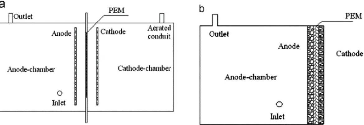
The dual-chamber design (Figure 2a), requires an anoxic anode chamber where anaerobic microorganisms oxidize an organic substrate, originating CO2, protons and electrons; a
PEM, that conducts protons and prevents the diffusion of O2 to the anode chamber; and a
cathode chamber, where atmospheric O2 is reduced, in the cathode, to water by the
presence of electrons and protons (Rahimnejad et al., 2015). Despite this, other configurations have been tested, such as the single-chamber MFC (Figure 2b) attempting to develop a simpler, cheaper and easier to scale-up system, where the cathode is directly exposed to air (Du, Li, & Gu, 2007; Liu Hong, 2004).
Figure 2 – General configurations of a double-chamber MFC, a, and single-chamber MFC, b. Adapted from Leong et al., 2013.
1.3.2.1. Anode
In a MFC, the anode function is to serve as physical support for the microorganisms to grow on, and to facilitate anodic microbial electron transfer; for this, the anode material must have good electric conductivity, low resistance, biocompatibility, chemical stability, high surface area and mechanical strength. Most anodes are made of carbon derived materials, namely graphite, in various geometrical arrangements, such as graphite rods, granules, cloth, fibres or carbon paper (Rahimnejad et al., 2015). In order to improve MFC output, nanomaterials, such as carbon nanotubes, and conducting composites of organic polymers, such as poly(tetrafluoroethylene) (PTFE) and polyaniline, and modified carbon or metals were used as base materials for the anode (Dutta & Kundu, 2014;
Rahimnejad et al., 2015).
1.3.2.2. Cathode
The cathode mediates the electron transfer from the external MFC electrical circuit to the cathodic chamber, where they reduce the final electron acceptor, which usually is O2, due
to its high oxidation potential, availability, and sustainability (Logan et al., 2006). Despite this, ferricyanide is also used, mainly at the experimental level, for its good performance when working with a carbon cathode. Ferricyanide needs, however, to be replaced when all ferricyanide is converted to ferrocyanide (oxidised form), and also impairs the MFC long term performance by diffusing into the anodic chamber (Logan et al., 2006; Rahimnejad
et al., 2015). As already referred, cathodes may be made of carbon (e.g. graphite), but this
platinum catalysts increases the fuel cell performance, as well as other compounds, such as ferric (Fe3+) and cobalt (Co) complexes and manganese oxide (Dutta & Kundu, 2014). Also, as an alternative to catalysis by oxygen oxidation, bio-cathodes have been tested, where the cathodic reactions are catalysed by microorganisms, without the need for abiotic catalysis or the addiction of artificial electron mediators. Bio-cathodes are generally described as enhancers of cathode performance and to improve MFC electrical production. Depending on the final electron acceptors, bio-cathodes can be anaerobic (e.g., nitrate and sulphate) or aerobic (O2) (Milner et al., 2016; Rahimnejad et al., 2015).
1.3.2.3. Proton exchange membrane
The PEM is one of the critical components of the MFC conventional design and has a significant impact in MFCs overall cost and performance (Leong et al., 2013;
Rahimnejad et al., 2015). In general terms, PEM function is to enable the transport of
protons from the anodic to the cathodic chamber, whilst preventing O2 diffusion to the
anodic chamber and substrate crossover to the cathodic chamber. PEM have negatively charged functional groups attached to the membrane matrix, thus allowing the transport of protons (as well as other positively charged ions) through the electrolyte, by diffusion, accordingly with the concentration differential (Rahimnejad et al., 2015). PEM resistance to proton crossover is one of the critical PEM characteristics, determining MFC power and current densities (Leong et al., 2013).
Nafion® is the most popular PEM for MFC applications, due to its high proton conductivity, originated by the negatively charged hydrophilic sulfonate groups. Nafion® is described as having some of MFCs best performances (Leong et al., 2013), notwithstanding, its high costs (about 38% of MFC total capital cost) (ElMekawy, Hegab,
Dominguez-Benetton, & Pant, 2013) lead to the application of several alternative PEMs
in MFCs, such as Ultrex®, Hyflon® or Zirfon®.
Some specific problems arise with the use of PEMs in MFC, namely biofouling, pH splitting or O2 diffusion. Biofouling, the growth of biofilms on the membrane surface is a
phenomenon that lowers both the transport rate of protons and the crossover of organic substrate to the cathodic chamber and which influence can be diminished by the development of anti-adhesion or anti-microbial techniques. pH splitting, a difference of pH on the anodic and cathodic chambers can drastically affect the MFC performance. This
occurs due to a competition for attachment with the PEM negatively charged sites with other cations present in solution (e.g. Na+, K+, Ca2+, Mg2+ and NH4+), reducing proton transport. pH splitting problems can be eliminated with the use of AEM that employ OH -as mobile ion. O2 diffusion to the anodic chamber impairs MFC performance, by
competing with the anode as a more favourable electron acceptor (Leong et al., 2013). The subject of the PEM for more generic fuel cell applications will be approached with more detail in the section 1.4 of this work.
1.3.3. Microorganisms used in MFC
Microorganisms have the ability to produce electrons from the metabolization of organic substrates. In a MFC, microorganisms are separated from the final electron acceptor so that electron transference to the MFCs anode is the only mean to restore intercellular electron mediators and complete respiration, hence originating electric current (Logan & Regan,
2006).
1.3.3.1. Bioelectrogenesis
The microorganism’s metabolic activities, either anabolism or catabolism, occur in the presence or absence of O2, thus describing the two major classes of microbial metabolism,
aerobic or anaerobic, respectively. Despite the class of microbial metabolism, microorganisms oxidise the available substrate, creating reducing equivalents, protons and electrons, in the form of redox carriers such as nicotinamide adenine dinucleotide (NAD+), flavin adenine dinucleotide (FAD+) or flavin mononucleotide (FMN+), among others. These carriers are essential in the generation of energy in the form of adenosine triphosphate (ATP) during respiration. In anaerobic conditions, reducing equivalents move through the electron transport chain until reaching a terminal electron acceptor. Concomitantly, a proton motive force is generated that assists in creating energy in the form of ATP. The terminal electron acceptor is determined upon the availability of the most thermodynamically suited compound, that is, the one with the higher reduction potential. In the presence of O2, that has the highest reduction potential in biological
systems, as well as being strongly electronegative, the reducing equivalents reduce O2 to
water. In the absence of O2, other compounds assume the function of terminal electron
the introduction of an artificial terminal electron acceptor (Mohan, Velvizhi, Modestra, &
Srikanth, 2014).
In a MFC, the anode artificially collects the produced electrons, assuming the terminal electron acceptor function in the anodic chamber and assuring the conditions for the microorganisms to maintain their biological functions by recuperating the redox potentials of intracellular mediators without a chemical terminal electron acceptor (e.g., O2, nitrates or sulphates) (Mohan et al., 2014). In a MFC, the anode potential has an
influence in the microorganism metabolism. With the decrease of the anode potential, the microorganisms are forced to deliver electrons through more reduced complexes, which will determine the redox potential of the final electron shuttle and, consequently, the microorganism’s metabolism. If the anode potential decreases in the presence of alternative terminal electron acceptors, such as sulphate or nitrate, microorganisms will transfer electrons to these compounds, lowering the MFC performance. Depending on the anode potential, microorganisms may assume high, medium or low redox oxidative metabolisms or fermentation (Rabaey & Verstraete, 2005).
1.3.3.2. Anodic electron transfer
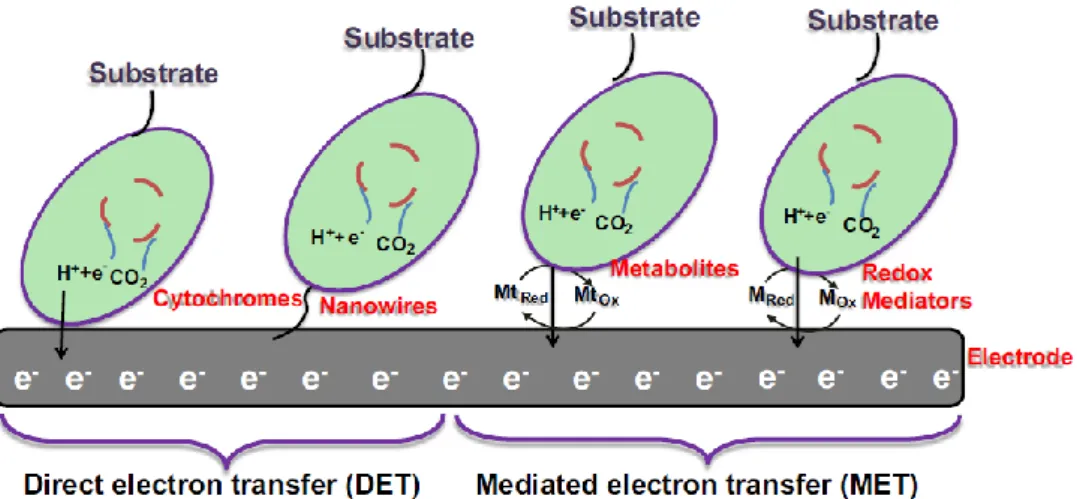
One of the critical features in the MFC performance, in what is directly related with the microorganisms’ nature and/or metabolism, is the electronic transference from the cells to the MFC’s anode, one of the limiting factors of MFC performance. The intracellular electrons produced by the organic substrate oxidation are transferred either by direct electron transfer (DET) or by mediated electron transfer (MET), as shown in Figure 3. Both this transfer systems depend, up to a certain extent, on membrane permeability for the establishment of transmembrane proteins, that facilitate the transport of electrons or for the transport of electron carriers (Mohan et al., 2014). The natural occurrence of electric transference phenomena in many bacterial communities (e.g. biofilms) is indicative of the biological relevance of this process in inter-bacteria communication and in quorum sensing processes (Logan, 2009; Mohan et al., 2014).
Figure 3 – Transference of electrons from bacteria to the anode can be performed directly, by DET (through membrane proteins or nanowires), or indirectly, by MET (through chemical mediators). Adapted from Rahimnejad et al., 2015.
For DET to occur, the microorganisms need to be in physical contact with the anode’s surface. This contact can either be established by trans-membrane proteins or by conductive pili known as nanowires. Membrane c-type cytochrome and multi-heme proteins are identified as potentially performing DET. The disadvantage of this membrane protein-mediated transference is bound with the fact that only the first biofilm layer, the one directly in contact with the anode, can perform DET, leaving unexplored most of the biofilm bioelectric potential. On the contrary, nanowire-mediated DET allows the formation of tick electroactive biofilms, with the establishment of a bacteria-to-bacteria and bacteria-to-anode network of electron conducing nanowires, described to increase anode performance (Schneider, Kovács, Rákhely, & Czeller, 2016; Mohan et al., 2014).
MET occurs when electron transference is mediated by shuttles that are reduced by electrons within the cell membrane and become oxidised in contact with the anode, usually being able to perform this process cyclically. A critical factor in MET is membrane permeability, indeed, MET rate is described to increase with the addition of membrane permeabilizers (e.g., chitosan, ethylenediaminetetraacetic acid and polyethyleneimine) or with the heterologous expression of porin proteins (Mohan et al., 2014). Electron mediators may be artificially added to the culture (e.g., neutral red, thionin or methyl viologen) (Rabaey & Verstraete, 2005) or be primary or secondary soluble metabolites endogenously produced by MFC cultures, such as flavins and phenazines (Schröder,
1.3.3.3. Microbial communities in MFC
MFC operate mostly with bacteria, though there are works where yeasts were applied in energy production (Raghavulu, Goud, Sarma, & Mohan, 2011). The cultures used in MFC can either be pure bacterial monocultures or mixed cultures, however, mixed cultures are often referred as producing higher MFC performances (Logan, 2009). This communities are originated from environmental samples, such as waste waters, sludge, sediments or purpose bioreactors and are frequently naturally electroactive (Logan, 2009;
Logan et al., 2006; Mohan et al., 2014). Despite the microorganism’s importance for
MFC operation, characteristics associated with fuel cell architecture and components, electrode spacing and solution conductivity are often more significant for the final fuel cell performance than the microorganism nature (Logan, 2009).
In MFC operation, pure cultures or bacterial isolates are mostly used in laboratory scale, for research purposes. Geobacter sulfurreducens, Rhodoferax ferrireducens,
Aeromonas hydrophila, Pseudomonas aeruginosa, Pseudomonas otitidis,
Geopsychronacter electrodiphilus, Desulfobulbus propionicus, Escherichia coli, Rhodopseudomonas palustris DX-1, Shewanella oneidensis and Shewanella haliotis are
some of the bacterial species and strains that were tested and found to be electrochemically active (Mohan et al., 2014). These microorganisms also produce nanowires, increasing anode-microorganism contact and MFC power density. Among this referred to species,
Geobacter and Shewanella are the most studied genera. While operating MFCs with pure
cultures, concerns with the maintenance of sterile conditions and the requirement for pure substrates are two of the major drawbacks (Mohan et al., 2014). Notably, 51% of the published studies concern MFC operation with pure cultures (Mercuri, Kumata, Amaral,
& Vitule, 2016).
MFCs operated with mixed cultures are typically open systems more focused on the industrial applications of waste water treatment/energy production (Mohan et al., 2014). The nature and composition of this communities varies accordingly with the type and availability of the substrate (Sotres, Tey, Bonmatí, & Viñas, 2016; Mohan et al., 2014), inoculum origin, reactor design and operational conditions. Despite higher power densities, MFC operated with mixed cultures, habitually show lower Columbic efficiencies due to complex metabolic reactions and mass transfer losses (Mohan et al., 2014). 34% of the published studies deal with MFC operation with mixed cultures (Mercuri et al., 2016).
1.3.4. Operational parameters
1.3.4.1. Temperature
MFCs are strongly affected by temperature alterations, due to its influence in process kinetics, mass transfer, thermodynamics and in the nature and distribution of the microbial communities. Regarding MFC performance, temperature is important to both power output and organic matter removal, and, generally, is higher as temperature increases. Higher temperatures also reduce fuel cell ohmic resistance and, thus, internal resistance, which can explain an increase in ionic conductivity. To note that the referred temperature increase is in the 30 to 45 ºC threshold, where biofilms have their maximum bio-electrocatalytic activity. Regarding the MFC start-up process, in which the influence of temperature is critical, higher initial temperatures are described to increase MFC performance, even if the long term operation is performed under lower temperatures (Oliveira, Simões, Melo, &
Pinto, 2013).
1.3.4.2. pH
pH constrains MFC operation in the way that it influences both the physiology of microorganisms and many of the fundamental process that regulate MFC operation, such as proton transport in PEM. Biologically, external pH fluctuations influence cytosolic pH, ion concentrations, membrane potentials and proton shuttling, not to mention the impact of pH in bacterial growth (Mohan et al., 2014). Continuous MFC operation leads to an accumulation of protons in the anodic chamber which decreases pH in this compartment, due to PEMs slow or inefficient proton transport. Concurrently, in the cathodic chamber, O2 reduction decreases proton concentration, increasing pH, in process known as pH
splitting (Leong et al., 2013).
Anodic chamber pH microenvironment is, thus, of critical importance, influencing bacterial metabolic activity, substrate oxidation and proton and electron production mechanisms. Once near-neutral conditions are optimal for bacterial growth, buffer systems are sometimes applied. An ideal buffer system for MFC should maintain pH constant, whereas facilitating proton transport, without interfering with bacterial activity or chemical reactions. Despite this, the use of chemical buffer systems is not practical for real MFC
applications, for it is associated with increasing cost and energy input (Oliveira et al.,
2013).
Generally, acidophilic operations are responsible for better MFC performances, if compared with neutral or alkaline operation, because of possible acidogenic pathways and higher cell proton gradient (Mohan et al., 2014).
1.3.4.3. Organic substrate
The type, nature and concentration of organic substrate utilized in a MFC influences the microorganism community and, hence, the fuel cell overall performance (Mohan et al.,
2014). Diverse substrates have been utilized in MFC operation, generally classified as
natural (e.g., gross domestic water, lactate, marine sediment, sewage sludge), or synthetic/ pure substrates (e.g., industrial wastewater, ethanol, glutamate, propionate, fumarate, acetate) (Mercuri et al., 2016). In general, complex waste waters are hard to metabolize due to long carbon chains and aromatic rings. Simple substrates originate many reducing equivalents, enhancing MFC performance. Wastewaters from industries or domestic activities are also considered good substrates, due to high quantities of degradable organic and fermentable solid products, such as the wastes from agriculture and human alimentation. Besides the influence on the microorganisms, the substrate organic load also influences fuel cell power densities and Coulombic efficiencies (Mohan et al., 2014).
1.3.5. MFC applications
The basic mode of operation and the process nature of MFCs are primarily conceptualized for wastewater treatment with simultaneous electricity production. Despite this, minor changes in MFC operation may expand the operational focus to bio-hydrogen production and biosensor applications (Rahimnejad et al., 2015).
Domestic wastewater contains more energy (about nine times more) than the amount that is needed to treat it through intensive aeration process, whereas the use of MFCs produces energy and yields a lower amount of sludge than the aeration process
(Logan, 2009). In this regard, MFCs can be used to treat wastewater from various human
activities, such as sanitary washes, food processing wastewaters or swine wastewaters, all rich in organic compounds, of which up to 90% of chemical oxygen demand (COD) can be removed. However, MFC bioelectricity production is still relatively low and more suited to
sustainable long-term power applications (Rahimnejad et al., 2015) or to remote power supply applications, where traditional power deliver systems, such as batteries, are not feasible (Logan, 2009). Additionally, compared with traditional methods, MFC wastewater treatment has a small environmental footprint and higher operational stability
(Mercuri et al., 2016).
MFC operation can be readily adapted to bio-hydrogen instead of electricity production, for this, the anode potential has to be increased, by voltage application and the cathode has to be deprived from O2 (Rahimnejad et al., 2015).
The bio-sensoric application of MFC can be harnessed for biological contamination determination or toxic compound activity detection. In the first case, a sterile fuel cell detects contamination by microorganisms by generating electricity when the microorganism establishes contact with the cell and produces energy. The presence of toxic compounds can be detected by a decrease in the power output of a MFC operated by a sensitive species (Schneider et al., 2016).
Another MFC application is in the remediation of soils contaminated by toxic metals, such as lead (Pb) or cadmium (Cd). In this field, MFC application is described to be feasible but not as effective as electrokinetic soil remediation, despite the advantage that with MFC mediated soil remediation the input of electricity is not required (Habibul, Hu,
& Sheng, 2016).
The interest in MFC research and development has increased in the last years, indeed, 84.7% of MFC-related studies were published between 2006 and 2014 (Mercuri et
al., 2016). The existence of studies comparing the efficiency of MFC electricity production
versus the cost of critical MFC components (e.g. Stoll, Ma, Trivedi, Spear, & Xu, 2016)
even with the sacrifice of performance, in order to determine cost-effective alternatives and the economical reliability of MFC operation is the evidence of MFC potentiality and general interest. Nevertheless, the main technological barrier for MFC wide application is the scale, still confined to small prototypes that are insufficient to produce electricity for practical proposes (Mercuri et al., 2016).
1.3.6. Limitations of MFC performance
A theoretical approach determined the maximum possible power density in 16.000 kW per fuel cell m3, based solely on the bacterial electrical potential (Logan, 2009). The fact that
these densities are not obtained is described as the responsibility of bottlenecks associated with cell architecture, component materials and several overpotentials. These overpotentials are discriminated as activation overpotentials, linked with the activation energy required for substrate oxidation on the anode or with O2 reduction on the cathode;
related with concentration polarizations, when compounds are being oxidized faster than their transport, leading to accumulations; and concerning ohmic losses, induced by electrical resistance of electrodes and electrolyte and low PEM conductivity (ElMekawy et
al., 2013).
1.4. Proton exchange membranes
An ideal PEM should have high proton conductivity (superior to 0.01 S cm-1) and low fuel permeability, as well as thermal, dimensional and hydrolytic stability. The first membranes to draw attention towards PEM development were perfluorosulphonic ionomer (PFSI) membranes, which were attractive due to their high proton conductivity and stability when exposed to oxidative or reductive environments (Bakangura, Wu, Ge, Yang, & Xu,
2015). In PFSI membranes, proton conductivity is thought to occur due to the combined
morphology of tetrafluoroethylene hydrophobic backbones and side chain hydrophilic-terminated sulphonic groups. When hydrated, the sulphonic groups form ionic clusters that create wide well-connected hydrophilic channels, allowing proton transport. PFSI membranes possess serious drawbacks, such as poor proton conductivity above 80 ºC, high production costs (Bakangura et al., 2015) and environmental problems (Gadim et al.,
2015). Additionally, PFSI membranes proton conductivity performance depends heavily in
the membrane hydration levels, as well as the mechanical properties (Hickner et al.,
2004). Notwithstanding, on MFC, the PEMs are always highly hydrated.
1.4.2. Proton conducting mechanisms
In solution, protons do not exist as isolated protons, but rather as hydrated proton molecules, namely as H5O2+ dihydronium ion complex or as H9O4+ complex. The high
proton conductivity in water is attributed to the exchange of protons along water molecules in contact by hydrogen bridges, known as proton wires. Protons propagate along a proton
wire, meaning that a proton leaving a proton wire is not the same that has entered it in the first place (Buch-Pedersen, Pedersen, Veierskov, Nissen, & Palmgren, 2009).
In hydrated polymeric matrixes, proton transport is described by two principal mechanisms, the “proton hopping” and the vehicular mechanisms where water functions as vehicle for proton transport (Figure 4) (Kim et al., 2015; Peighambardoust,
Rowshanzamir, & Amjadi, 2010).
According to the proton hopping mechanism, also known as structural diffusion, protons are transferred from one hydrolysed ionic site, such as SO3- or H3O+, to another
across the membrane. (Peighambardoust et al., 2010). When plotted in an Arrhenius plot, the proton conductivity, if behaving according with this mechanism, follows the Vogel-Tamman-Fulcher (VTF) model, that describes the behaviour of protons at higher temperatures or lower relative humidity (RH). According with this model, the movement and flexibility of the membrane polymer, dependent of the glass transition temperature, has a great importance in proton hopping in long ranges (Di, Piga, Giffin, & Pace, 2012;
Gadim et al., 2017; Giffin et al., 2012).
By the vehicular proton transport mechanism, hydrated protons (hydronium ions), diffuse through the membrane aqueous medium according with the electrochemical gradient. For this it is essential the existence of free water volumes in the matrix (Kim et
al., 2015), which are created by the hydrophobic nature of the hydrated membrane polymer
backbone (Peighambardoust et al., 2010) in synergy with the hydrophilic side chain sulphonic groups (Bakangura et al., 2015). This transport mechanism follows the Arrhenius model, that describes the proton behaviour for membranes in conditions of lower temperatures and higher RH associated with lower polymer flexibility (Di et al.,
Figure 4 – Proton vehicular and hopping mechanisms in a hydrated PFSI membrane. Adapted from Kim et al., 2015.
1.4.3. PEM matrix polymers
The polymer chemical structure has a significant influence in the membrane properties. Therefore, polymer polarity, glass transition temperature, thermal stability and solubility are very important characteristics (Bakangura et al., 2015). For PEM applications, glassy thermoplastic polymers are mostly used, due to their excellent film-forming abilities, dynamic flexibility and thermal stability. Non-conducting polymers require the attachment of protogenic groups to the polymer chain. PFSI polymers exhibit excellent electrochemical properties and chemical stability but their high cost lead to the development of polymers with fluorite-free structures (Bakangura et al., 2015).
1.4.3.1. Fluorinated polymers
Fluorocarbon polymer based PEM, due to the fluorite small size and high electronegativity have strong C–F bonds and low polarizability (Peighambardoust et al., 2010). These polymers show high thermal stability, chemical inertness and proton conductivity (Kim et
al., 2015; Peighambardoust et al., 2010), attributed to the high PTFE backbone acidity as
well as to the side chain sulphonic groups. PFSI membranes form uniform and effective water channels, showing good electric properties, despite the low water uptake. These membranes are the most used for PEMFC applications, being, however, hard and costly to prepare and assemble. The most used PFSI PEM is Nafion®, despite the existence of similar polymeric alternatives, such as Aciplex™, Flemion™ and Fumapem®, produced by diverse companies (Kim et al., 2015).
1.4.3.2. Non-fluorinated polymers
The drawbacks of PSFI membranes lead to the development of alternative solutions for PEM production, among which are the non-fluorinated polymers (Bakangura et al.,
2015). These can be aliphatic or aromatic polymers, with the latter having benzene ring
structures in the polymer backbone or side chains (Peighambardoust et al., 2010) that allow the hydrocarbon membranes to be easily designed according with predetermined properties. Additionally, the monomers are cheaper than PSFI (Kim et al., 2015) and
easily recycled by conventional methods. Generally, hydrocarbon polymers with polar groups have high water uptake capacity over a wide range of temperatures (Kim et al.,
2015; Peighambardoust et al., 2010), with water channel formation and enhanced proton
conductivity and also showing elevated thermal and mechanical stability. However, non-fluorinated hydrocarbon membranes have lower oxidative and chemical stability, when compared with fluorinated ones (Kim et al., 2015) though some of this differences may not relevant on the context of MFC operation. Some of the most relevant hydrocarbon polymers for PEM applications are polyether sulphones, polyether ketones, polyesters and poly(arylene ethers) (Kim et al., 2015; Peighambardoust et al., 2010).
1.5. Bacterial cellulose
Cellulose is the most abundant natural polymer, being estimated that 1011 to 1012 tonnes of cellulose are produced by photosynthesis every year. Cellulose may derive from various sources, namely from wood, seed fibres (e.g., cotton, coir), bast fibres (e.g., flax, hemp), grasses (e.g., bagasse, bamboo), marine animals (e.g., tunicate), algae, fungi, invertebrates and bacteria. Wood is the most significant source of industrial cellulose, where it is found associated with hemicelluloses, lignin, extractives and inorganic salts (Nechyporchuk et
al., 2015).
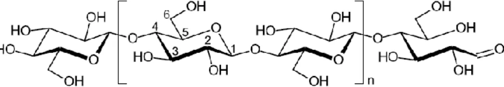
At the molecular level, cellulose is a linear homopolymer of D-glucose units, covalently linked by β(1→4) glycosidic bonds that leads to a flat conformation (Figure 5). This arrangement allows the formation of intra- and inter-molecular hydrogen bonds, responsible for cellulose crystallinity and mechanical properties (Panaitescu, Frone, &
Chiulan, 2015). The cellulose polymer repeat unit, known as cellobiose units, comprises
two anhydrous glucose rings, as shown between brackets in Figure 5 (Eichhorn et al.,
2010). The degree of polymerization of native cellulose ranges from 10 000 to 44 000
glucose monomers, depending on the source (Nechyporchuk et al., 2015).
Figure 5 – Cellulose polymer, highlighting the cellobiose unit between brackets, as well as the non-reducing (left) and non-reducing (right) end groups. Adapted from Nechyporchuk et al., 2015.
Cellulose chains are arranged in elementary fibrils that are in turn aggregated into larger microfibrils with 5 to 50 nm in diameter and several microns of length. Cellulose is considered a semi-crystalline polymer, due to the existence of both crystalline and amorphous regions in cellulose fibrils (Moon, Martini, Nairn, Simonsen, &
Youngblood, 2011).
The nanotechnological revolution further increased the scope of cellulose applications via the introduction of nanocellulosic substrates. Nanocelluloses are classified as nanofibrilated cellulose, when obtained by mechanical processes, as cellulose nanocrystals or nanowhiskers, when produced by acidic treatment, and as bacterial nanocellulose (Panaitescu et al., 2015) when synthesized by bacteria. Nanofibrillated cellulose and cellulose nanocrystals are obtained in a top-down process by the treatment and disintegration of vegetable cellulose fibers, whilst bacterial cellulose produced in a bottom-up process by the build-up of cellulose nanofibers (Nechyporchuk et al., 2015).
Bacterial cellulose (BC) is a high purity cellulose produced by some aerobic bacteria in aqueous medium from sugars. BC has the same chemical structure as vegetable cellulose, though being free from other biopolymers such as hemicelluloses and lignin
(Nechyporchuk et al., 2015). Additionally, after purification, BC has only hydroxyl
functional groups, (Klemm et al., 2011; Nechyporchuk et al., 2015) unlike wood-based cellulose, that often presents carbonyl or carboxyl groups, introduced by the cellulose treatment and purification processes. BC is found in the form of twisting ribbons, with cross-sections of 3-4 nm × 70-140 nm of area and more than 2 µm in length. The BC degree of polymerization varies from 3000 to 9000 and shows a crystallinity of 80 to 90%
(Nechyporchuk et al., 2015), while vegetable cellulose crystallinity ranges from 40 to
60% (Cacicedo et al., 2015).
The BC biogenesis is done by aerobic bacteria as a way to guarantee access to atmospheric O2 and protection against UV radiation or aggressive chemical environments.
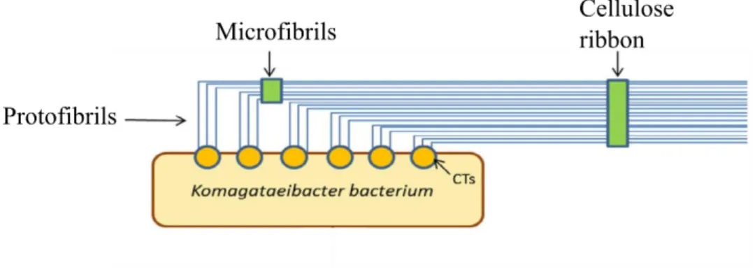
BC biosynthesis follows a three-level hierarchical structure. Initially, about 16 synthetized cellulose chains are extruded from pores in the bacteria cellular wall, originating a first assembly with 1.5 nm in diameter that combines in 3 to 4 nm diameter protofibrils. These arrange in crystalline microfibrils (20 nm width), which, in turn, associate in flat cellulose
ribbons with 80 to 120 nm in diameter and length of hundreds of microns. This process is schematized in Figure 6 (Panaitescu et al., 2015).
Figure 6 – Schematized process of BC production. Adapted from Cacicedo et al., 2015.
BC is mostly produced by bacteria found in environments where the fermentation of sugars occurs, such as damaged fruits, unpasteurized juices, beers or wines. The most relevant genera are Komagataeibacter (formerly known as Acetobacter and as
Gluconacetobacter (Yamada, 2014)), Sarcina, Agrobacterium and Rhizobium (Cacicedo
et al., 2015), despite only Komagataeibacter sp. being able to produce BC at commercial
levels and Komagataeibacter xylinus remaining the model strain for research and commercial purposes (Figueiredo, Vilela, Neto, Silvestre, & Freire, 2014). Physiologically, the Komagataeibacter genus is characterized by the ability to metabolize ethanol to acetic acid, oxidate acetate and lactate to carbon dioxide and water, and to be able to grow in the presence of 0.35% (w/v) acetic acid, without the production of 2,5-diketo-D-gluconate from glucose; additionally, the Komagataeibacter genus is morphologically unable of mobility. The Komagataeibacter species are strict aerobic, Gram-negative bacteria, found predominantly in fruits and vegetables in decomposition, where they metabolize carbon sources such as glucose, fructose, sucrose, mannitol and glycerol, among others, in temperatures ranging from 25 to 30 ºC and pH of 3 to 7. The production of cellulose in the culture medium-air interface works as a fluctuation mechanism, allowing the bacteria to have simultaneous access to O2 and nutrients, while
also functioning as a physical barrier to protect the bacteria from external aggressions, increasing the ability to colonize other substrates and, due to the BC hydroscopic nature, retaining moisture, thus preventing dehydration (Cacicedo et al., 2015).
The interest in BC as a biodegradable biopolymer has increased significantly in recent years with the development of many BC-based composites, that take advantage of
the BC unique set of characteristics as well as with the interest to develop methods to produce BC at commercial levels (Figueiredo et al., 2014).
1.5.1. BC production
The synthesis of of BC by K. xylinus is a three step process: i) polymerization of glucose residues with β(1→4) glycosidic bonds; ii) extracellular extrusion of linear cellulose chains and, iii) organization and crystallization of cellulose microfibrils through the establishment of hydrogen bonds and van der Waals interactions (Jozala et al., 2016). The cultivation method and conditions have a significant influence in the BC final structure and physical and mechanical properties (Figueiredo et al., 2014). The culture medium is the most important factor to the final BC cost, which has propelled the research towards the identification of low-cost culture mediums, that could improve BC yields and economic viability (Jozala et al., 2016).
BC production is often performed in the Hestrin-Schramm (HS) medium that uses glucose as main carbon source. In order to find cheaper mediums, alternative carbon sources have been tested, such as xylose, maltose, starch, polyols (e.g., glycerol) or residues and industrial wastes (e.g. grape bagasse or dry olive mill residue) (Figueiredo et
al., 2014). Other strategies envision the addition of inductors to activate the microorganism
energetic metabolism and/or reduce the formation of metabolic by-products (Cacicedo et
al., 2015).
Diverse fermentation dynamics have also been tested, namely, batch, fed-batch and continuous fermentations, under static or agitated conditions. However, the impact of the different dynamics in BC physical characteristics, properties and morphology must be acknowledged (Cacicedo et al., 2015).
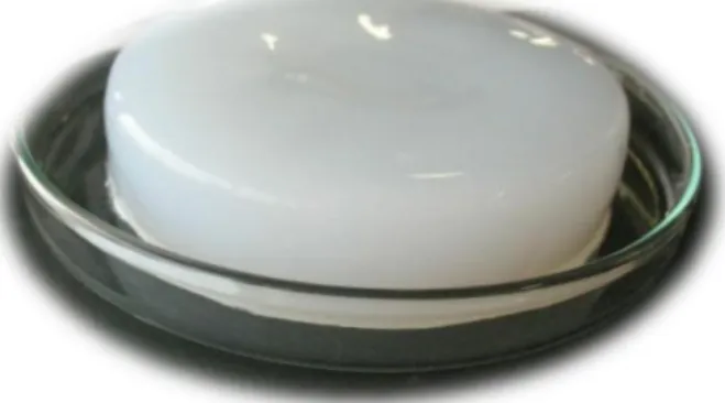
BC production under static conditions is the most common method, originating highly hydrated cellulose membrane (Figure 7). These membranes are originated in the culture medium-air interface where the increase in thickness forces the mature BC membrane to sink, allowing the bacteria to maintain O2 access. With the use of shaped
casts, it is possible to give predetermined forms to the membrane for specific applications
(Figueiredo et al., 2014). This method yields membranes with high internal surface area,