Development of a system for communication and control of
an electrical spindle
THANG VAN TRAN
Dissertação do MIEM
Orientadores:
Prof. Manuel Rodrigues Quintas Prof. Paulo Augusto Ferreira de Abreu
Mestrado Integrado em Engenharia Mecânica
1 Abstract
Today, the beauty is one of the main major in enjoying. The things which people wear are very important. So shoes are one aspect contributing for that. However, shoes making is based on small and medium enterprises with an intensive manual labor. This structure has strong barriers to the automation of technological processes, which affect productivity, giving it a strong dependence of labor-skilled personal and low flexibility. What is executed in this project is to improve an existing robotic system for finishing operations of shoes. The robotic system includes a robot carrying a shoe, a device carries a cutting tool, a control unit which control the velocity of the tool depend on the position of tool
Keyword: Finishing operation, robotic system, automation global architecture.
3 Acknowledgments.
Start here by expressing a deep gratitude to my advisors, Professor Manuel Quintas and Professor Paul Abreu for their support, availability and tireless dedication throughout this semester. For the long hours spent with me in seeking solutions to problems that arose with the development of this project, and the sharing of knowledge that helped me at various stages to improve this work, I leave here my sincere thanks.
I also thank the coordinator of the Lotus project, the staff Ana Paiva, the monitoring done during this period, and for her constructive criticism.
I would also like to thank my colleagues in the automation option, especially when Carlos, Patricia, Antonio and Na, the help they gave and for the good times of fellowship and relaxation with table soccer ("matraquilhos")
To my friends in general, to colleagues with whom I shared the house, my friends from Erasmus, for their support and memories we are building together in recent years and will never forget.
Finally I would like to thank my family, especially my brother, my parents and my grandparents, who are an example of life for me and always supported me in all circumstances, so I often do not always the easiest way is most helpful.
5
Table of Contents
1. Introduction ... 9
1.1 Introduction ... 9
1.2 Objectives of the Project ... 10
2. The Existing Robot System and Features ... 11
2.1 Introduction ... 11
2.2 The Robotic System ... 11
2.2.1 Hardware ... 11
2.2.2 Principle of Operation of Finishing Process ... 14
2.3 The Characteristic of Current System ... 17
3. Development of the new Control Unit ... 19
3.1 Introduction ... 19
3.2 New Global Architecture ... 19
3.3 Control Unit Architecture... 20
3.3.1 Description of Architecture... 20
3.3.2 Devices for the Control Unit ... 22
3.4 Software Development ... 25
3.4.1 Development Tool ... 25
3.4.2 Control Algorithm ... 27
3.5 Conclusion ... 29
4. Implementation of the new Control Unit ... 31
4.1 Introduction ... 31
4.2 Simulation ... 31
4.3 Hardware Prototype... 34
4.4 Conclusion ... 34
6
6. References ... 37
Appendix A: Delta Ac Driver ... 39
Appendix B: Mcp4821 ... 47
Appendix C: Pic 4432 ... 49
Appendix D: Schematic for Electronic Board of Control Unit... 53
Appendix E: The Detail Flow Chart ... 55
7 List of Figures
Figure 2.1 - Robot ABB IRB2400 and robot controller IRC5 [ABB Robotic,2010] ... 12
Figure 2.2 - Tool mounted on force control device. [Viana,2010] ... 12
Figure 2.3 - Direction of force control [Viana, 2010] ... 13
Figure 2.4 - Structure of control force device [Viana, 2010] ... 14
Figure 2.5 - Reference position of the tool. [Viana, 2010] ... 16
Figure 2.6 - Operating principle of the system [Viana,2010] ... 16
Figure 2.7 - Global architecture system. ... 17
Figure 3.1 - New global architecture. ... 20
Figure 3.2 - Control unit architecture ... 21
Figure 3.3 - MCP 48821 image... 23
Figure 3.4 - PIC 18f4431 ... 23
Figure 3.5 - AC motor driver [ Delta, 2010] ... 24
Figure 3.6 - CCS C compiler ... 25
Figure 3.7 - The mode 1 graph... 28
Figure 3.8 - The mode 2 graph... 28
Figure 3.9 - The outline flowchart. ... 29
Figure 4.1 - ISIS interface.[Proteus,2010] ... 32
Figure 4.2 - Electronic diagram for simulation. ... 33
Figure 4.3 - Hardware prototype ... 34
9
1.
Introduction
1.1
Introduction
This thesis is organized in five chapters. The first chapter presents an introduction about this project, an overview of project. The second chapter describes the robotic system for finishing soles of shoes and the auxiliary device which will be integrated into the finish that best meet the requirements and meets the resources available. The robotic system presented was developed for finishing shoes soles, but it can be applied well for any finishing operation of others product. A global architecture is mentioned so that reader can understand operation of robotic system.
The third chapter refers the strategy to be adopted in implementing the new control unit, goes through the construction and integration into the old control unit, the new control block for tool velocity, conceived in this project in view of the requirements thereof and analyzed previously.
In this chapter, there are sections as new global architecture, control unit architecture, description of architecture, devices in control unit, software development, development tool control algorithm. Following sections in order to understand clearly about new control unit.
The fourth chapter focuses on implementation control unit of developed in the third chapter. All procedures carried out to test and validate the proposed solution are explained in detail here as well as the tests conducted and the experimental results. Furthermore, this section presents the prototype, simulation for work done above. The last chapter presents the global conclusions.
10
1.2
Objectives of the Project
The objective of this work involves the development of a system to control the speed of an electrical spindle to be used in a device used in robotic machine operations. The device has a linear actuator, with a position sensor, that supports the spindle. The device has a microcontroller that reads the data from a position sensor and send that data to the robot controller. It is now envisage to add the capability of controlling the speed of the spindle through a new microcontroller. For that purpose, the microcontroller must be connected to the driver of the spindle, to send a reference velocity signal and to start/stop the motor. So far, the actual device where the spindle will be fitted has been developed. The device has a pneumatic actuator so that the contact force can be regulated through pneumatic valves, having a position sensor (encoder) to measure the position of tool. The current implementation, based on a microcontroller, enables to communicate the position data to the robot controller through a RS232 link. The proposed work must now be built on top of the existing system, so that it will be possible to control the speed of the spindle. With this implementation it will be possible to implement a cooperative working mode between the device with the spindle and the robot. The implementation of the speed control will be based on the microcontroller.
11
2.
The Existing Robot System and Features
2.1
Introduction
This chapter describes the finishing robotic system for shoes and the auxiliary device which is integrated into the robotic cell. The robotic system is developed for finishing shoes soles, but it can be applied well for any finishing operation of others product. A global architecture is mentioned so that the reader can understand the robotic system operation.
2.2
The Robotic System
2.2.1
Hardware
Typically the robot cell concept includes the presence of certain systems. These systems apart from including the existence of a robot and its controller, include a tool carried by the robot, a system of supply / removal of products, positioning systems, safety mechanisms. The robot cell available to this project, has only the basic systems, such as the robot (and its controller) and the finishing device.
Robot & Robot Controller
The robot used in this project is an ABB IRB2400 available at the Robotics Laboratory Department of Mechanical Engineering, Faculty of Engineering, University of Porto, with its driver IRC5 (Figure 1.1). This six-axis manipulator has a maximum range of 1.5m, a maximum load capacity of 16kg and a repeatability of 0.06mm. [ABB Robotic ,2010]
12
Figure 2.1 - Robot ABB IRB2400 and robot controller IRC5 [ABB Robotic,2010] Tool & spindle
It was determined that the cutting tool used was a cylindrical cutter because of its advantages. The diameter and number of teeth of the tool, are two factors to take into account when choosing the tool. Tools with small diameter have a lower peripheral velocity which implies a higher speed of the tool, while the excessive increase of their diameter cannot ensure a desired finish on parts with tight contours. Increasing the number of teeth provides a better finish, but also allows the accumulation of material between the cutting edges, resulting in unwanted heating of the tool, and a bad cut. Thus, it was chose a generic cutter with 20mm in diameter with three straight teeth.
13 Auxiliary Device for Control Contact Force
Given the equipment available in the robotics lab, Faculty of Engineering, University of Porto, it has been adopted setting the robot centered in the cell (Figure 2.2), being the most appropriate configuration to existing conditions. To perform the finishing operations of the soles of shoes it was conceived an auxiliary device that supports the tool, which the robot moves the shoes. It is intended that its construction is simple, economical and appropriate use of a robot controlled in position and velocity. Studied the generic settings possible for the finishing device, and once in performing the finishing operations of the soles of shoes you want to use a robot with 6 degrees of freedom, was conceived an auxiliary finishing device fixed outside the robot, that supports the tool.
Figure 2.3 - Direction of force control [Viana, 2010]
The robot is responsible for handling the shoe. The contact force that can be adjusted is exerted in the direction perpendicular to the surface to be machined. Thus, taking advantage
Direction Of Force Control
14 of the ability to position / orientation and the multiplicity of available configurations that such a robot has, it is possible to implement force control system with reduced complexity. Neglecting the forces generated by the cutting process, a direction of force control is sufficient for this system, since the robot ensures the perpendicularity of the sole of the shoe relative to the direction in which the force is controlled. The device has one linear degree of freedom linear for force control. As can be seen in Figure 2.3, the contact force should be controlled in the direction perpendicular to the surface to be machined. The robot is responsible for ensuring the continuous positioning of the shoe, orienting it correctly in relation to the tool, so that is only necessary to provide one direction for force control. It is intended to eliminate the need for the existence of a system of force control in the robotic arm, with higher cost.
Figure 2.4 - Structure of control force device [Viana, 2010]
2.2.2
Principle of Operation of Finishing Process
The operating principle of the system which is intended to implement is dependent on the properties of the auxiliary device to finish. Thus, it is necessary to define its functional characteristics firstly.
15 Device Characterization
In the idealized setting, the auxiliary device is fixed in the workspace of the robot, and has two fundamental characteristics:
• Allows adjustment of contact force between the tool that carries along a linear degree of freedom, and the shoe that is manipulated by robot;
• Allows measurement of linear displacement corresponding to the position of the tool. The contact force adjustment is performed in a passive manner, using a pneumatic actuator system and adjusting the pneumatic pressure. The displacement is measured using a linear incremental encoder. A micro controller reads and processes the encoder signal and sends to the robot controller the position data through a serial port, using the principles of communication via RS-232.
The device has also an adjustable mechanical stop to allow the limitation of the current positioning of the axis of the tool.
Principle of Operation of the System
In the planned design, the robot is controlled in position and velocity trajectory and carries the shoe that will be machined in the fixed auxiliary device, outside the robot. The robot manipulates the shoe to ensure squarness of the sole from the cutting tool. It is intended that the robot describes a known trajectory, with a preset speed, traversing a set of points corresponding to the desired final shape of the contour of the sole of the shoe. During execution of the cutting motion, the description of the trajectory is tangential to the cutting tool. This remains at its reference position (defined by setting a mechanical stop), where the real contour of the shoe’ sole resembles geometrically to its desired shape, imposed by the path (Figure 2.5).
16 Figure 2.5 - Reference position of the tool. [Viana, 2010]
In this situation, the default speed of the path is updated (reduced) by the robot controller, depending on the signal received from the position of the tool. Thus, the default speed of execution of the trajectory will be continuously updated in terms of greater or lesser amount of material to remove.
The diagram of Figure 2.6 shows the components and working principle of the system it that is available.
Figure 2.6 - Operating principle of the system [Viana,2010]
Figure 2.6 shows the operating principle of the existing system. The robot controller is used to command the robot which manipulate a shoe. The tool is operated at a fixed speed. The position of the tool is measured and communicated through the serial port to the robot
Reference position Adjustable mechanic stop controller T O O L Robot encoder Actuator Interface measurement, monitoring and reporting
17 controller. The execution speed of the robot trajectory is adjusted, depending on the value of
the position. Figure 2.7 show the global architecture of the existing system
Figure 2.7 - Global architecture system.
2.3
The Characteristic of Current System
Tests carried out with this system were able to identity some problems. The update of the robot path velocity is achieved but with a constant time delay. This is due to the time it takes the robot controller to update the velocity and not from the time it takes to send the position data from the device to the controller. This behavior has implications in the material remove rate that can be achieved.
To improve the machining operations, it was found necessary to provide the tool with a variable cutting speed.
19
3.
Development of the new Control Unit
3.1
Introduction
This chapter presents the new global architecture, the description of the control unit architecture, and its components, the, and the development of the control algorithm.
The strategy to be adopted in improving the existing device goes through the construction and integration existing device with a new control unit for tool velocity adjustment.
It is intended so that the new control unit has the following characteristics • Compatible with the old control unit
• Provide an interface to the ac driver driven the spindle • Provide an interface to cope with alarm conditions • Measure and display the working position of the tool • Ability to control velocity based on the position of the tool • Ability to communicate position data via serial port connection.
3.2
New Global Architecture
Because of the disadvantages shown in section 2, the envisaged solution to overcome these problems involves controlling the velocity of the tool based on the position of the tool. In the old architecture, a control unit was made to receive the position signal from the encoder of the pneumatic system then send it to robot controller. Figure 3.1 shows the new architecture. As showed the velocity of the tool is depended on the position of the tool. For that purpose, an AC spindle motor controlled with a variable frequency driver (Delta VFD-B) was chosen.
20 Figure 3.1 - New global architecture.
As it is compared with the old global architecture, there are two more hardware components. There is an AC driver that will be referred at the beginning of section 3 and a control unit. The input for each control unit is the position tool signal sent from encoder. But the unit 2 will output a control signal for tool velocity. So the difference is clear now. There are more extra functions for control unit 2 listed step by step into each section.
3.3
Control Unit Architecture.
3.3.1
Description of Architecture
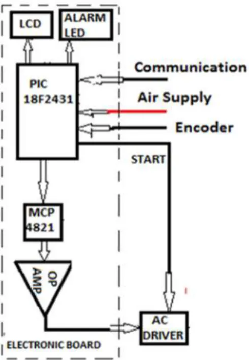
It is necessary to design a device which is suitable with all the requirements presented. Considerations about input and output signals are very important. For input signals it was considered the need to cope with the encoder signal, the user interface communication and signal that monitors the presence of the air supply that is required to operate the spindle. The output signals considered are reference voltage for the ac driver, the LCD display and a led to be used as an alarm indicator.
21 Figure 3.2 - Control unit architecture
Figure 3.2 shows the architecture of the control unit that is based on the microcontroller Pic 18F4431. The input signals are connected directly to the Pic. To provide the analog output signal that connects to the ac driver it was necessary since the microcontroller can only output signals in the range from 0v to 4v and the ac driver requires a signal from 0v to 10v.
22
3.3.2
Devices for the Control Unit
The following table lists all components used for the control unit.
N Component
1. Power button
2. Switch “on/off”
3. Voltage Regulator Max 667
4. Led
5. Pic 18f4431
6. Digital to analog converter MCP4821
7. Keypad 8. LCD 9. Capacitors 10. Resistors 11. Amplifier. 12. Ac driver. Digital to Analog MCP 4821 Description
The microchip MCP4821 device is 2.7-5.5V, low power, low DNL, 12 bit digital to analog converters (DACs) with internal band gap voltage reference, optional 1 buffered output and serial peripheral interface(SPI). The MCP4821 DACs provide high accuracy and low noise performance for industrial applications where calibration or compensation of signals (such as temperature, pressure and humidity) are required. The MCP4821 are available in the extended temperature range and PDIP, SOIC and MSOP packages. The MCP4821 includes one-buffered registers, allowing simultaneous updates using the LDAC pin. The device also
incorporates a Power – on Reset(POR) circuit to ensure reliable power- up (Figure 3.4) [MCP Datasheet, 2010]
23
Figure 3.3 - MCP 48821 image
This component, it have SPI interface with 20 MHZ clock support, precision selectable voltage reference, low power dace. It is voltage- output string DACs.
The coding of the device is straight binary, with the ideal output voltage given by equation PIC 18f4431 Description Figure 3.4 - PIC 18f4431
The microcontroller used is the PIC 18F4432 from Microchip, and is the central element of this control unit (Figure 3.5). This micro controller from Microchip was chosen to integrate this circuit, because it belongs to a family of micro controllers whose characteristics are perfectly suited to the requirements.
This component has a serial communications interface, which allows for serial communication with other devices, and an interface for connection of incremental encoder
24 QEI (Quadrature Encoder Interface) capable of measuring speeds, directions and detect changes of direction. It also has an internal oscillator that can be programmed to the desired clock frequency, thus eliminating the need to incorporate external crystals in the system electronics. The frequency used was 8 MHz. The clearly description of this chip is in appendix C. [Pic datasheet, 2010]
The programming of this element was made using the card electronics mikroElektronika's development Easypic 4, and its software programming mikroC. The programming code used in this system is in Appendix E.
AC motor driver: Delta VDF – B Series: Description
The driver considered is from Delta Electronics Company [Delta, 2010]. The model VFD-B represents Delta's NEMA1 general purpose AC drive. The VFD-B series drive is rated to provide constant torque, featuring open and closed loop vector control. Delta offers an optional 2000 Hz high speed output that can be factory programmed at the customer's request.
25
3.4
Software Development
3.4.1
Development Tool
This section presents the developments of the software for the control unit 2. First, the requirements for programming involved the choice of an integrated developing environment (IDE). Among the ones available, the Micro C and CCS were considered. It was chosen CCS as it provides flexible environment bases on standard computing language. It also have large library of function which is easy for user.
CCS Overview
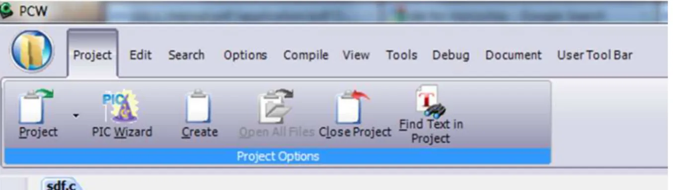
CCS for use in this project is 4.122 PCW Compiler version (2011). The latest versions of multiple-function 3227 is new and new functions, new update. Their programming for the PIC 12 bit, 14 bit and PIC 18. the menus and toolbars are set-up in specially organized Ribbon. Each Ribbon relates to a specific type of activity and is only shown when selected. CCS has included a “user toolbar” ribbon that allows the user to customize the ribbon for individual needs. [CCS, 2011]
Figure 3.6 - CCS C compiler
Program syntax
A program is made up of the following four elements in a file: • Comment
• Pre-Processor Directive • Data Definition
26 Every C program must contain a main function which is the starting point of the program execution. The program can be split into multiple functions according to their purpose and the functions can be called from the main or the sub functions. In a large project functions can also be placed in different C files or header files that can be included in the main C file to group the related functions by their category. CCS C also requires to include the appropriate device file using #include directive to include the device specific functionality. There are also some preprocessor directives like #fuses to specify the fuses for the chip and #use delay to specify the clock speed. The functions contain the data declarations, definitions, statements and expressions. The compiler also provides a large number of standard C libraries as well as other device drivers that can be included and used in the programs.
Here is a sample program with explanation using CCS C to read analogue samples over RS232:[4]
///////////////////////////////////////////////////////
/// This program displays the min and max of 30, /// /// comments that explains what the program does, /// /// and A/D samples over the RS-232 interface. /// ///////////////////////////////////////////////////////
#if defined(__PCM__) // preprocessor directive that chooses the compiler #include <16F877.h> // preprocessor directive that selects the chip PIC16F877
#fuses HS,NOWDT,NOPROTECT,NOLVP // preprocessor directive that defines fuses for the chip
#use delay(clock=20000000) // preprocessor directive that specifies the clock speed
#use rs232(baud=9600, xmit=PIN_C6, rcv=PIN_C7) // preprocessor directive that includes the rs232 libraries
#if defined(__PCH__) // same as above but for the PCH compiler and PIC18F452 #include <18F452.h>
#fuses HS,NOWDT,NOPROTECT,NOLVP #use delay(clock=20000000)
#use rs232(baud=9600, xmit=PIN_C6, rcv=PIN_C7) #endif
void main() { // main function
int i, value, min, max; // local variable declaration
printf("Sampling:"); // printf function included in the RS232 library setup_port_a( ALL_ANALOG ); // A/D setup functions- built-in
27 setup_adc( ADC_CLOCK_INTERNAL ); // A/D setup functions- built-in
set_adc_channel( 0 ); // A/D setup functions- built-in do { // do while statement
min=255; // expression max=0;
for(i=0; i<=30; ++i) { // for statement
delay_ms(100); // delay built-in function call
value = Read_ADC(); // A/D read functions- built-in if(value<min) // if statement
min=value;
if(value>max) // if statement max=value;
}
printf("\n\rMin: %2X Max: %2X\n\r",min,max); } while (TRUE);
} [CCS,2011]
3.4.2
Control Algorithm
Two modes definition
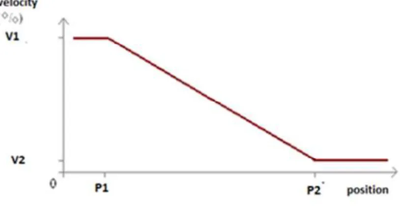
The control algorithm implements two modes of operation to define the velocity reference (to be sent to the driver) based on the measurement position of the tool. The first mode generates a continuous reference velocity (see figure 3.7). The second mode generates a two level discrete reference (see figure 3.8). The user has the choice of choosing one of these control modes and to define the parameters for that.
28 Figure 3.7 - The mode 1 graph
The following graph in Figure 3.8 presents the second mode.
Figure 3.8 - The mode 2 graph.
29 Figure 3.9 presents an outline flowchart for algorithm.
Figure 3.9 - The outline flowchart.
More detailed flowcharts are presented in Appendix E.
3.5
Conclusion
This section presents the reasons & solution for a new control unit. At the beginning, it presents about reasons then introduce a new global architecture. Inside the new global architecture, there is a new control unit described carefully, from architecture to device, from development tool to control algorithm.
Star Mode 1 or Mode 1 Mode 2 Enter or Mode Star Mode
31
4.
Implementation of the new Control Unit
4.1
Introduction
The fourth chapter focuses on the implementation of the control unit presented in the third chapter. All procedures carries out to test and validate the proposed solution are explained in detail here, and the tests conducted and the experimental results. Also, this section shows simulations and prototype built.
4.2
Simulation
The developed control unit, based on the Microchip microcontroller was first simulated on a software from Proteus System. The software tool is ISIS – intelligent schematic input system [Figure 4.1] ISIS provides full control of the drawing appearance in terms of line widths, fill styles, colors and fonts. This enables to produce attractive schematics like the ones seen on magazines rather than the 'thin line' diagrams often associated with older CAD software. Once your drawing is complete you can export it as a graphics file or copy it to the clipboard for incorporation in other documents. This makes ISIS ideal for use in producing technical documentation, academic papers, project reports, as well as being an excellent front end for PCB design. The drawing appearance is defined in terms of a style template - especially useful if you want to apply a ‘house style’ to all your designs. Furthermore, the scheme allows you to customize the appearance of the library parts supplied with the package.
32
Figure 4.1 - ISIS interface.[Proteus,2010]
Library device.
ISIS comes with a device library including over 10,000 parts. The libraries include standard symbols, transistors, diodes, thermionic valves, TTL, CMOS, ECL, microprocessor and memory parts, PLDs, analog ICs and op-amps as well as manufacturer specific libraries from National Semiconductor, Philips, Motorola, Teccor, Texas and Zetex. More libraries are being created as part of an ongoing program.
Schematic diagram.
Based on a demo version of ISIS, available for download from the Proteus website, it was simulated the control unit developed.
To conduct this simulation it was necessary to draw the electronic schematic, as shown in Figure 4.2. There is not enough symbols in ISIS to present devices for electronic devices. It is necessary to choose blocks which have the same characteristics with device but differ in name. For example, to simulate the encoder signal it was used from the library of ISIS, a block called Encoder – motor. The display and keypad are standard elements of the library. A switch present for air supply connection. A button used for start button. A led present for alarm in real system and a multimeter is used for showing output signal.
33
Figure 4.2 - Electronic diagram for simulation.
The following list explains simulation symbols used for the electronic diagram.
1. The motor–encoder used to generate the encoder signal which present the position signal. The signal can be increased or decreased when the switch 1 (10) turn on or turn off. 2. Dc voltmeter presents for multimeter measuring output analog signal.
3. Switch – SPST presents for air supply connection. If the air is connected, the switch is closed
4. The standard LCD LM016L 5. Keypad smallcallc
6. The button presents the start button in real system.
7. The led green presents for alarm in real system: when there are something happened such as air supply is not connected, the alarm will ring.
8. The pic 18f4431
9. The led – biddy presents for enable another device. 10.The mcp4821
11.Two switches – SPDT two change direction of motor mean changing increasing or decreasing encoder signal
34 After drawing schematic diagram, the ccs tool compile to hex file. In ISIS, there is a function which allow to input hex file for simulation. It just need to be directed to the directory.
4.3
Hardware Prototype
After having the control unit fully defined in the simulation software, it was built a hardware version of it. For that purpose it was used a breadboard where the components were assembled and connected. It was used a rotary encoder. To check the analog output signal that is send to the driver of the motor, it was used a multimeter, apart from being possible to read its value in the programed display. The pic18f4431 & mcp4821 are new from the laboratory of Mechanical Department. The LCD used has 2 rows, each one having 16 characters. The keypad is a new one from the lab in Mechanical Department. The power supply is a Tektronix PS282 to generate a voltage 5 volts through a new MAX667.
Figure 4.3 - Hardware prototype
4.4
Conclusion
Once the implementation of the developed system and the simulation taken as required to assess their behavior, we can have several conclusions. The developed control unit 2 fulfills the requirements established for the system. The user can choose two modes operating. Reference voltage change whenever input signal change. Simulation work made both in Proteus and bread board. Simulation in Proteus is easier than in bread board.
35
5.
Conclusions and Recommendations
This project took near 4 months in the laboratory of Mechanical Department. The procedure happened as following. The initial time was taken study the current existing system identifying its capability and disadvantages.
Then it was defined a new control architecture for operating the existing system. This had to the choice of implementing a new control unit, based on a microcontroller. The requirements for this control unit were established both in terms of hardware and in operating condition. This control unit was first simulated with the ISIS software, and then an hardware version was built on a breadboard.
The experimental results were able to confirm the functionality of the simulated and the hardware version of the developed control unit.
The work for future is building the prototype on a circuit board, connecting the prototype to the system, and testing the new control unit working with the robotic cell.
37
6.
References
[1]ABB. ABB Robotics. www.abb.com/robotics 2010. [2]ABB. ABB Robotics. www.abb.com/review 2010. [3]CCS. Reference manual,2011.
[4]Delta Electronic Inc. VFD-B Reference manual 2005 [5]Mcp4821 Datasheet 2010.
[6]Pic18f4431 Datasheet 2010.
[7]Proteus. Reference manual ISIS, 2010.
[8]Viana, Desenvolvimento de uma Solução Robótica para Opẻações de Acabamento de Solas de Solas de Sapatos, Msc Thesis, FEUP, 2010
39
Appendix A: Delta Ac Driver
A: Version Type
23: Mains Input Voltage
21:230V Single phase 23:230V Three phase 43:460V Three phase
B: B Series
007: Applicable motor capacity
007: 1 HP(0.7kW) 150: 20HP(15kW) 022: 3 HP(2.2kW) 220: 30 HP(22kW) 037: 5 HP(3.7kW) 300: 40HP(30kW) 055: 7.5HP(5.5kW) 370: 50 HP(37kW) 075: 10 HP(7.5kW) 450: 60HP(45kW) 110: 15 HP(11kW) 550: 75HP(55kW) 750: 100HP(75kW)
VFD: Series Name (Variable Frequency Drive)
Features
Specific Control Terminal
The importance thing user must know about ac driver are control terminal. This following list is all control terminal and function of ac motor.
43 Operation method.
Description of the digital keypad VFD – PU01.
Group Parameters.
The VFD-B parameters are divided into 12 groups by property for easy setting. In most applications, the user can finish all parameter settings before start-up without the need for re-adjustment during operation. The 12 groups are as follows:
Group 0: User parameters Group 1: Basic parameters
44 Group 3: Output function parameters
Group 4: Input function parameters
Group 5: Multi-step speed and PLC parameters Group 6: Protection parameters
Group 7: Motor Parameters Group 8: Special Parameters
Group 9: Communication Parameters Group 10: PID Control Parameters
Group 11: Fan & Pump Control Parameters
User can choose group parameter to set up depend on case of project is. Some group is need to set in standard for every time. The choice of the right AC motor drive for the application is very important and has great influence on its lifetime. If the capacity of AC motor drive is too large, it cannot offer complete protection to the motor and motor maybe damaged. If the capacity of AC motor drive is too small, it cannot offer the required performance and the AC motor drive maybe damaged due to overloading. But by simply selecting the AC motor drive of the same capacity as the motor, user application requirements cannot be met completely. In according to consider all the conditions, including load type, load speed, load characteristic, operation method, rated output, rated speed, power and the change of load capacity. The following table lists the factors considered to choose ac motor.
47
Appendix B: Mcp4821
Programmable Gain Block
The rail to rail output amplifier has configurable gain, allowing optimal full-scale outputs for differing voltage reference inputs. The output amplifier gain has two selections, a gain of 1v/v(GA=1) or a gain of 2v/v (GA=0).
The output range is 0.000v to 4095/4096*2.048v when G=1, and 0.000 to 4095/4096*4.096v when G= 2. The default value for this bit is gain of 2, yielding an ideal full- scale output of 0.000v to 4.096v due to the internal 2.048v Vref
Voltage Reference.
The MCP 4821 device utilize internal 2.048v voltage reference. The voltage reference has low temperature coefficient and low noise characteristics.
Power – on Reset Circuit
The power- on reset circuit ensures that the DACs power-up with SHDN=0(high- impedance). The device will continue to have a high-impedance output until a valid write command is performed to either of the DAC register and the LDAC pin meets the input low threshold. If the power supply voltage is less than the power on reset threshold (Vpor=2.0, typical), the DACs will be held in their reset state. They will remain in that state until Vdd>Vpor and a subsequent write command is received.
Shutdown Mode
Shutdown mode can be entered by using either hardware or software commands. In the device there is pin SHDN available. During Shutdown mode, the supply current is isolated from most of the internal circuitry. The serial in the serial interface remains active, thus allowing a write command to bring the device out of shutdown mode.
Serial interface
The MCP 4821 family is designed to interface directly with the SPI port, available on many microcontrollers, and supports mode 0,0 and mode 1,1. Commands and data are sent to the device via the SDI pin, with data being clocked-in on the rising edge of SCK. The communications are unidirectional and, thus, data cannot be read out of the MCP4821 device. The CS pin must be held low for the duration of a write command. The write command consists of 16 bits and is used to configure the DAC’s control and data latches. Register 5-1 details the input registers used to configure and load the DAC register.
48 Write command
The write command is initiated by driving the CS pin low, followed by clocking the four configuration bits and the 12 data bits into the SDI pin on the rising edge of SCK. The CS pin is then raised, causing the data to be latched into the selected DAC’s input registers. The MCP4821 use a buffered latch to allow DAC’s outputs to be synchronized with the LDAC pin, if desired. Upon the LDAC pin achieving a low state, the values held in the DAC’s input register and are transferred in to DAC’s output registers. The output will transition to the value and held in the DAC register. All writes to the MCP4821 device are 16 bits words. Any clocks past 16 will be ignored. The most significant four bits are configuration bits. The remaining 12 bits are data bits. No data can be transferred into the device with CS high. This transfer will only occur if 16 clocks have been transferred into the device. If the rising edge of CS occurs prior, shifting of data into the input registers will be aborted.
49
Appendix C: Pic 4432
This chip offers the advantages of all PIC18 microcontrollers namely, high computational performance at an economical price, with the addition of high endurance enhanced Flash program memory and a high-speed 10-bit A/D converter. On top of these features, the PIC18F2331/2431/4331/4431 family introduces design enhancements that make these microcontrollers a logical choice for many high performance, power control and motor control applications. These special peripherals include:
• 14-bit resolution Power Control PWM Module (PCPWM) with programmable dead time insertion
• Motion Feedback Module (MFM), including a 3-channel Input Capture (IC) Module and Quadrature Encoder Interface (QEI)
• High-speed 10-bit A/D Converter (HSADC) the PCPWM can generate up to eight complementary PWM outputs with dead-band time insertion. Overdrive current is detected by off-chip analog comparators or the digital fault inputs (FLTA, FLTB). The MFM Quadrature Encoder Interface provides precise rotor position feedback and/or velocity measurement. The MFM 3 X input capture or external interrupts can be used to detect the rotor state for electrically commutated motor applications using Hall Sensor feedback, such as BLDC motor drives. PIC18F2331/2431/4331/4431 devices also feature Flash program memory and an internal RC oscillator with built-in LP modes.
Feature Used for this Application
The Motion Feedback module is a special-purpose peripheral designed for motion feedback applications. It provides a variety of control solutions for a wide range of electric motors. The module actually consists of two hardware sub-modules:
• Input Capture module (IC)
• Quadrature Encoder Interface (QEI).
Many of the features for the IC and QEI sub modules are fully programmable, creating a flexible peripheral structure that can accommodate a wide range of in-system uses. In this section the QEI sub modules is used because it is suitable with quadrature encoder feedback. Three QEI inputs: two phase signals (QEA and QEB) and one index signal (INDX)
• Direction of movement detection with a direction change interrupt (IC3DRIF),16-bit up/down position counter, standard and high-precision position tracking modes, two position
50 update modes (x2 and x4), velocity measurement with a programmable post scale for high-speed velocity measurement, position counter interrupt (IC2QEIF in the PIR3 register) velocity control interrupt (IC1IF in the PIR3 register), the QEI sub-module has three main components: the QEI control logic block, the position counter and velocity post scale.
QEI Operation
The Position Counter register pair (POSCNTH: POSCNTL) acts as an integrator, whose value is proportional to the position of the sensor rotor that corresponds to the number of active edges detected. POSCNT can either increment or decrement, depending on a number of selectable factors which are decoded by the QEI logic block. These include the count mode selected, the phase relationship of QEA to QEB (“lead/lag”), the direction of rotation, and if a reset event occurs. The logic is detailed in the sections that follow.
QEIM2: QEIM0
Mode/ Reset Description
000 QEI disable
001 x2
update/index pulse
Two clocks per QEA pulse. INDX resets POSCNT.
010 x2 update/
Period match
Two clocks per QEA pulse. POSCNT reset by the period match(MAXCNT).
011 _ unused
100 _ unused
101 x4 update/
index
Four clocks per QEA and QEB PULSE pair. INDX resets POSCNT.
110 x4 update/
Period match
Four clocks per QEA and QEB PULSE pair.
POSCNT reset by the period Match(MAXCNT).
111 _ Unused
51 SPI MODE
SPI mode allows 8 bits of data to be synchronously
transmitted and received simultaneously. To accomplish communication, typically three pins are used:
• Serial Data Out (SDO) – RC7/RX/DT/SDO • Serial Data In (SDI) – RC4/INT1/SDI/SDA • Serial Clock (SCK) – RC5/INT2/SCK/SCL
Additionally, a fourth pin may be used when in a Slave mode of operation: • Slave Select (SS) – RC6/TX/CK/SS
When initializing the SPI, several options need to be specified. This is done by programming the appropriate control bits in the SSPCON register (SSPCON<5:0>) and SSPSTAT<7:6>. These control bits allow the following to be specified:
• Master mode (SCK is the clock output) • Slave mode (SCK is the clock input) • Clock polarity (Idle state of SCK)
• Clock edge (output data on rising/falling edge of SCK)
• Clock rate (Master mode only) • Slave Select mode (Slave mode only)
53
Appendix D: Schematic for Electronic Board of Control
55
Appendix E: The Detail Flow Chart
no no Star Air key = yes Start no yes Pls Select mode 1 2 Select 1 or no yes Mode...: P1: _ P2: Enter p1 & p2 Enter or Clear Enter Enter v1 & v2 Clear Enter or Enter
56 Enter P < p1 P > p2 Mode 1 Mode no Yes Mode 1 : P… Vout V1: Mode 2 : P… Vout V2 Stop Enter to switch Stop to reset Enter or Pls select mode: 1 2 Start Switch Stop mode P < p1 p1 < P < p2 Mode v = v1 - (p – p1)(p2-p1)/(v1-v2) Mode1 : P: ... Vout: v1 Mode1 : P: ... Vout: v
57
Appendix F: Code Programming for Control Unit Board
LCD
/////////////////////////////////////////////////////////////////////////////// //// LCD.C ////
//// Driver for common LCD modules //// //// ////
//// lcd_init() Must be called before any other function. //// //// ////
//// lcd_putc(c) Will display c on the next position of the LCD. //// //// \a Set cursor position to upper left ////
//// \f Clear display, set cursor to upper left //// //// \n Go to start of second line //// //// \b Move back one position ////
//// If LCD_EXTENDED_NEWLINE is defined, the \n character //// //// will erase all remanining characters on the current ////
//// line, and move the cursor to the beginning of the next //// //// line. ////
//// If LCD_EXTENDED_NEWLINE is defined, the \r character //// //// will move the cursor to the start of the current ////
//// line. //// //// ////
//// lcd_gotoxy(x,y) Set write position on LCD (upper left is 1,1) //// //// ////
//// lcd_getc(x,y) Returns character at position x,y on LCD //// //// ////
//// CONFIGURATION ////
//// The LCD can be configured in one of two ways: a.) port access or //// //// b.) pin access. Port access requires the entire 7 bit interface ////
//// connected to one GPIO port, and the data bits (D4:D7 of the LCD) //// //// connected to sequential pins on the GPIO. Pin access //// //// has no requirements, all 7 bits of the control interface can //// //// can be connected to any GPIO using several ports. //// //// ////
//// To use port access, #define LCD_DATA_PORT to the SFR location of //// //// of the GPIO port that holds the interface, -AND- edit LCD_PIN_MAP //// //// of this file to configure the pin order. If you are using a ////
//// baseline PIC (PCB), then LCD_OUTPUT_MAP and LCD_INPUT_MAP also must //// //// be defined. ////
//// ////
//// Example of port access: ////
//// #define LCD_DATA_PORT getenv("SFR:PORTD") //// //// ////
//// To use pin access, the following pins must be defined: //// //// LCD_ENABLE_PIN ////
//// LCD_RS_PIN //// //// LCD_RW_PIN ////
58 //// LCD_DATA4 //// //// LCD_DATA5 //// //// LCD_DATA6 //// //// LCD_DATA7 //// //// ////
//// Example of pin access: ////
//// #define LCD_ENABLE_PIN PIN_E0 //// //// #define LCD_RS_PIN PIN_E1 //// //// #define LCD_RW_PIN PIN_E2 //// //// #define LCD_DATA4 PIN_D4 //// //// #define LCD_DATA5 PIN_D5 //// //// #define LCD_DATA6 PIN_D6 //// //// #define LCD_DATA7 PIN_D7 //// //// ////
///////////////////////////////////////////////////////////////////////////////
//// (C) Copyright 1996,2010 Custom Computer Services //// //// This source code may only be used by licensed users of the CCS C //// //// compiler. This source code may only be distributed to other //// //// licensed users of the CCS C compiler. No other use, reproduction //// //// or distribution is permitted without written permission. //// //// Derivative programs created using this software in object code //// //// form are not restricted in any way. ////
///////////////////////////////////////////////////////////////////////////
// define the pinout.
// only required if port access is being used. typedef struct
{ // This structure is overlayed
BOOLEAN enable; // on to an I/O port to gain BOOLEAN rs; // access to the LCD pins. BOOLEAN rw; // The bits are allocated from BOOLEAN unused; // low order up. ENABLE will int data : 4; // be LSB pin of that port.
#if defined(__PCD__) // The port used will be LCD_DATA_PORT. int reserved: 8;
59 #endif
} LCD_PIN_MAP;
// this is to improve compatability with previous LCD drivers that accepted // a define labeled 'use_portb_lcd' that configured the LCD onto port B. #if ((defined(use_portb_lcd)) && (use_portb_lcd==TRUE))
#define LCD_DATA_PORT getenv("SFR:PORTB") #endif
#if defined(__PCB__)
// these definitions only need to be modified for baseline PICs.
// all other PICs use LCD_PIN_MAP or individual LCD_xxx pin definitions. /* EN, RS, RW, UNUSED, DATA */
const LCD_PIN_MAP LCD_OUTPUT_MAP = {0, 0, 0, 0, 0}; const LCD_PIN_MAP LCD_INPUT_MAP = {0, 0, 0, 0, 0xF}; #endif
////////////////////// END CONFIGURATION ///////////////////////////////////
#ifndef LCD_ENABLE_PIN
#define lcd_output_enable(x) lcdlat.enable=x #define lcd_enable_tris() lcdtris.enable=0 #else
#define lcd_output_enable(x) output_bit(LCD_ENABLE_PIN, x) #define lcd_enable_tris() output_drive(LCD_ENABLE_PIN) #endif
#ifndef LCD_RS_PIN
#define lcd_output_rs(x) lcdlat.rs=x #define lcd_rs_tris() lcdtris.rs=0 #else
#define lcd_output_rs(x) output_bit(LCD_RS_PIN, x) #define lcd_rs_tris() output_drive(LCD_RS_PIN) #endif
60 #ifndef LCD_RW_PIN
#define lcd_output_rw(x) lcdlat.rw=x #define lcd_rw_tris() lcdtris.rw=0 #else
#define lcd_output_rw(x) output_bit(LCD_RW_PIN, x) #define lcd_rw_tris() output_drive(LCD_RW_PIN) #endif
// original version of this library incorrectly labeled LCD_DATA0 as LCD_DATA4, // LCD_DATA1 as LCD_DATA5, and so on. this block of code makes the driver // compatible with any code written for the original library
#if (defined(LCD_DATA0) && defined(LCD_DATA1) && defined(LCD_DATA2) && defined(LCD_DATA3) && !defined(LCD_DATA4) && !defined(LCD_DATA5)
&& !defined(LCD_DATA6) && !defined(LCD_DATA7)) #define LCD_DATA4 LCD_DATA0
#define LCD_DATA5 LCD_DATA1 #define LCD_DATA6 LCD_DATA2 #define LCD_DATA7 LCD_DATA3 #endif
#ifndef LCD_DATA4 #ifndef LCD_DATA_PORT #if defined(__PCB__)
#define LCD_DATA_PORT 0x06 //portb #define set_tris_lcd(x) set_tris_b(x)
#else
#if defined(PIN_D0)
#define LCD_DATA_PORT getenv("SFR:PORTD") //portd #else
#define LCD_DATA_PORT getenv("SFR:PORTB") //portb #endif
#endif #endif
61 #if defined(__PCB__)
LCD_PIN_MAP lcd, lcdlat; #byte lcd = LCD_DATA_PORT #byte lcdlat = LCD_DATA_PORT #elif defined(__PCM__)
LCD_PIN_MAP lcd, lcdlat, lcdtris; #byte lcd = LCD_DATA_PORT #byte lcdlat = LCD_DATA_PORT
#byte lcdtris = LCD_DATA_PORT+0x80 #elif defined(__PCH__)
LCD_PIN_MAP lcd, lcdlat, lcdtris; #byte lcd = LCD_DATA_PORT #byte lcdlat = LCD_DATA_PORT+9 #byte lcdtris = LCD_DATA_PORT+0x12 #elif defined(__PCD__)
LCD_PIN_MAP lcd, lcdlat, lcdtris; #word lcd = LCD_DATA_PORT #word lcdlat = LCD_DATA_PORT+2 #word lcdtris = LCD_DATA_PORT-0x02 #endif
#endif //LCD_DATA4 not defined
#ifndef LCD_TYPE
#define LCD_TYPE 2 // 0=5x7, 1=5x10, 2=2 lines #endif
#ifndef LCD_LINE_TWO
#define LCD_LINE_TWO 0x40 // LCD RAM address for the second line #endif
#ifndef LCD_LINE_LENGTH #define LCD_LINE_LENGTH 20 #endif
62 BYTE const LCD_INIT_STRING[4] = {0x20 | (LCD_TYPE << 2), 0xc, 1, 6};
// These bytes need to be sent to the LCD // to start it up. BYTE lcd_read_nibble(void); BYTE lcd_read_byte(void) { BYTE low,high; #if defined(__PCB__) set_tris_lcd(LCD_INPUT_MAP); #else
#if (defined(LCD_DATA4) && defined(LCD_DATA5) && defined(LCD_DATA6) && defined(LCD_DATA7)) output_float(LCD_DATA4); output_float(LCD_DATA5); output_float(LCD_DATA6); output_float(LCD_DATA7); #else lcdtris.data = 0xF; #endif #endif lcd_output_rw(1); delay_cycles(1); lcd_output_enable(1); delay_cycles(1); high = lcd_read_nibble(); lcd_output_enable(0); delay_cycles(1); lcd_output_enable(1);
63 delay_us(1); low = lcd_read_nibble(); lcd_output_enable(0); #if defined(__PCB__) set_tris_lcd(LCD_OUTPUT_MAP); #else
#if (defined(LCD_DATA4) && defined(LCD_DATA5) && defined(LCD_DATA6) && defined(LCD_DATA7)) output_drive(LCD_DATA4); output_drive(LCD_DATA5); output_drive(LCD_DATA6); output_drive(LCD_DATA7); #else lcdtris.data = 0x0; #endif #endif
return( (high<<4) | low); }
BYTE lcd_read_nibble(void) {
#if (defined(LCD_DATA4) && defined(LCD_DATA5) && defined(LCD_DATA6) && defined(LCD_DATA7))
BYTE n = 0x00;
/* Read the data port */ n |= input(LCD_DATA4); n |= input(LCD_DATA5) << 1; n |= input(LCD_DATA6) << 2; n |= input(LCD_DATA7) << 3;
64 return(n); #else return(lcd.data); #endif } void lcd_send_nibble(BYTE n) {
#if (defined(LCD_DATA4) && defined(LCD_DATA5) && defined(LCD_DATA6) && defined(LCD_DATA7))
/* Write to the data port */
output_bit(LCD_DATA4, bit_test(n, 0)); output_bit(LCD_DATA5, bit_test(n, 1)); output_bit(LCD_DATA6, bit_test(n, 2)); output_bit(LCD_DATA7, bit_test(n, 3)); #else lcdlat.data = n; #endif delay_cycles(1); lcd_output_enable(1); delay_us(2); lcd_output_enable(0); }
void lcd_send_byte(BYTE address, BYTE n) { #if defined(__PCB__) set_tris_lcd(LCD_OUTPUT_MAP); #else lcd_enable_tris(); lcd_rs_tris(); lcd_rw_tris(); #endif
65 lcd_output_rs(0); while ( bit_test(lcd_read_byte(),7) ) ; lcd_output_rs(address); delay_cycles(1); lcd_output_rw(0); delay_cycles(1); lcd_output_enable(0); lcd_send_nibble(n >> 4); lcd_send_nibble(n & 0xf); } #if defined(LCD_EXTENDED_NEWLINE) unsigned int8 g_LcdX, g_LcdY;
#endif void lcd_init(void) { BYTE i; #if defined(__PCB__) set_tris_lcd(LCD_OUTPUT_MAP); #else
#if (defined(LCD_DATA4) && defined(LCD_DATA5) && defined(LCD_DATA6) && defined(LCD_DATA7)) output_drive(LCD_DATA4); output_drive(LCD_DATA5); output_drive(LCD_DATA6); output_drive(LCD_DATA7); #else lcdtris.data = 0x0; #endif lcd_enable_tris(); lcd_rs_tris();
66 lcd_rw_tris(); #endif lcd_output_rs(0); lcd_output_rw(0); lcd_output_enable(0); delay_ms(15); for(i=1;i<=3;++i) { lcd_send_nibble(3); delay_ms(5); } lcd_send_nibble(2); for(i=0;i<=3;++i) lcd_send_byte(0,LCD_INIT_STRING[i]); #if defined(LCD_EXTENDED_NEWLINE) g_LcdX = 0; g_LcdY = 0; #endif }
void lcd_gotoxy(BYTE x, BYTE y) { BYTE address; if(y!=1) address=LCD_LINE_TWO; else address=0; address+=x-1;
67 lcd_send_byte(0,0x80|address); #if defined(LCD_EXTENDED_NEWLINE) g_LcdX = x - 1; g_LcdY = y - 1; #endifd } void lcd_putc(char c) { switch (c) {
case '\a' : lcd_gotoxy(1,1); break;
case '\f' : lcd_send_byte(0,1); delay_ms(2); #if defined(LCD_EXTENDED_NEWLINE) g_LcdX = 0; g_LcdY = 0; #endif break; #if defined(LCD_EXTENDED_NEWLINE) case '\r' : lcd_gotoxy(1, g_LcdY+1); break; case '\n' : while (g_LcdX++ < LCD_LINE_LENGTH) { lcd_send_byte(1, ' '); } lcd_gotoxy(1, g_LcdY+2); break; #else
case '\n' : lcd_gotoxy(1,2); break; #endif
68
case '\b' : lcd_send_byte(0,0x10); break; #if defined(LCD_EXTENDED_NEWLINE) default : if (g_LcdX < LCD_LINE_LENGTH) { lcd_send_byte(1, c); g_LcdX++; } break; #else
default : lcd_send_byte(1,c); break; #endif
} }
char lcd_getc(BYTE x, BYTE y) {
char value;
lcd_gotoxy(x,y);
while ( bit_test(lcd_read_byte(),7) ); // wait until busy flag is low lcd_output_rs(1); value = lcd_read_byte(); lcd_output_rs(0); return(value); }
69 Program for digital to analog converter: MCP4821
#ifndef EEPROM_SELECT
#define DAC_CS PIN_C6 #define DAC_CLK PIN_C5 #define DAC_DI PIN_C7 #define DAC_LDAC PIN_C3
#endif void init_dac() { output_high(DAC_CS); output_high(DAC_LDAC); output_high(DAC_CLK); output_high(DAC_DI); }
void write_dac(int16 data, int8 ga) { BYTE cmd[3]; BYTE i; cmd[0]=data; cmd[1]=(data>>8); cmd[2]=ga; output_high(DAC_LDAC); output_low(DAC_CLK); output_low(DAC_CS);
70 for(i=0; i<=23; ++i)
{
if(i<4 || (i>7 && i<12)) shift_left(cmd,3,0); else { output_bit(DAC_DI, shift_left(cmd,3,0)); output_high(DAC_CLK); output_low(DAC_CLK); } } output_high(DAC_CS); output_low(DAC_LDAC); delay_us(10); output_HIGH(DAC_LDAC); }
71 Program for KBD
//Keypad connection: #define row0 PIN_B4 #define row1 PIN_B5 #define row2 PIN_B6 #define row3 PIN_B7 #define col0 PIN_B0 #define col1 PIN_B1 #define col2 PIN_B2 #define col3 PIN_B3
// Keypad layout:
char const KEYS[4][4] = {{1,2,3,'A'},
{4,5,6,'B'}, {7,8,9,'C'}, {'*',0,'#','D'}};
#define KBD_DEBOUNCE_FACTOR 20 // Set this number to apx n/333 where // n is the number of times you expect
// to call kbd_getc each second
void kbd_init() { //set_tris_b(0xF0); //output_b(0xF0); port_b_pullups(true); }
short int ALL_ROWS (void) {
72 return (0); else return (1); } char kbd_getc() {
static byte kbd_call_count; static short int kbd_down; static char last_key; static byte col;
byte kchar; byte row; kchar=0xff; if(++kbd_call_count>KBD_DEBOUNCE_FACTOR) { switch (col) { case 0: output_low(col0); output_high(col1); output_high(col2); output_high(col3); break; case 1: output_high(col0); output_low(col1); output_high(col2);
73 output_high(col3); break; case 2: output_high(col0); output_high(col1); output_low(col2); output_high(col3); break; case 3: output_high(col0); output_high(col1); output_high(col2); output_low(col3); break; } if(kbd_down) { if(!ALL_ROWS()) { kbd_down=false; kchar=last_key; last_key=0xff; } } else { if(ALL_ROWS()) { if(!input (row0)) row=0;
74 row=1;
else if(!input (row2)) row=2;
else if(!input (row3)) row=3; last_key =KEYS[row][col]; kbd_down = true; } else { ++col; if(col==4) col=0; } } kbd_call_count=0; } return(kchar); }
75 Main program:
#include <18F4431.h>
#FUSES NOWDT //No Watch Dog Timer
#FUSES INTRC_IO //Internal RC Osc, no CLKOUT #FUSES NOCPD //No EE protection
#FUSES NOPROTECT //Code not protected from reading #FUSES MCLR //Master Clear pin enabled
#FUSES NOPUT //No Power Up Timer
#FUSES BROWNOUT //Reset when brownout detected
#BYTE QEICON=0xFB6 // quadrature configure #bit QEICONDIR=0xFB6.5
#BYTE DFLTCON=0xF60 // quadrature noise filter configure #BYTE CAP2BUFL=0xF66 // position counter
#BYTE CAP2BUFH=0xF67
#BYTE CAP3BUFL=0xF64 //max count #BYTE CAP3BUFH=0xF65
#BYTE OSCCON = 0xFD3
#use delay(internal=8Mhz) //#use fast_io(B)
#define LCD_ENABLE_PIN PIN_D3 #define LCD_RS_PIN PIN_D1 #define LCD_RW_PIN PIN_D2
#define LCD_DATA4 PIN_D4 #define LCD_DATA5 PIN_D5 #define LCD_DATA6 PIN_D6 #define LCD_DATA7 PIN_D7
76 #include <C:\Documents and Settings\Administrator\My
Documents\Downloads\project\lcd.c>
#include <C:\Documents and Settings\Administrator\My Documents\Downloads\project\mcp4821.c>
#include <C:\Documents and Settings\Administrator\My Documents\Downloads\project\kbd.c>
#define WARNING PIN_C4 #define Control PIN_C2 int8 time= 20;
int1 stop = 1,pause = 0,start = 0; int1 dac1=0, dac2=0;
unsigned char k;
unsigned int16 get_input2 (char x, char y){ unsigned int16 kb = 0; //unsigned int16 p = 0; unsigned char k; lcd_gotoxy(x,y); lcd_send_byte(0,0x0f); printf(lcd_putc,"%3ld",kb); do{ do k=kbd_getc(); while (k == 0xff); if (k < 10){ // p = kb; kb = 10*kb + k; lcd_gotoxy(x,y); printf(lcd_putc,"%3ld",kb); } if (k == 'B'){ kb = kb/10; lcd_gotoxy(x,y); printf(lcd_putc,"%3ld",kb);
77 } } while (k != 'A'); return(kb); }
int1 check_pin0(int pin){ if(input(pin))--time; else time = 20;
if(time == 0) return(0); else return(1);
}
int1 check_pin1(int1 pin){ char t = 50; if(!input(pin)){ do { delay_ms(5); --t; }while((!input(pin)) & (t > 0)); } return(input(pin)); }
int1 check_pin2(int1 pin){ char t = 20; int1 r; if(!input(pin)){ do { delay_ms(5); --t; }while((!input(pin)) & (t > 0)); while(!input(pin)){ r = 0; t = 20; do { delay_ms(5);
78 --t; }while((input(pin)) & (t > 0)); } } else r = 1; return(r); } #INT_TIMER0 Void Check_air ( ) { setup_timer_0(T0_OFF); if(k == 0xff) k = kbd_getc(); if(stop){ stop = check_pin0(PIN_A0); output_bit(WARNING,stop); }else{ QEICON=0; write_dac(0,1); lcd_putc("\fAir supply\n"); lcd_putc("turn off"); do{ while(check_pin2(PIN_A1)); } while(check_pin1(PIN_A0)); stop = 1; lcd_putc("\f"); dac1 = 0; dac2 = 0; QEICON=0xB4; } if(pause){ QEICON=0; write_dac(0,1); do k = kbd_getc();
79 while(k != 'D'); pause = 0; k =0xff; dac1 = 0; dac2 = 0; QEICON=0xB4; } setup_timer_0(T0_INTERNAL | T0_DIV_1); set_timer0(-4000); } void main() {
unsigned int8 v1,v2,pi1,pi2; char mode;
unsigned int16 p1,p2; signed int16 position=0; int16 length = 0; float32 x,vout; //OSCCON=OSC_8Mhz; // OSCCON = OSC_31KHZ; setup_oscillator(OSC_8Mhz);
// QEICON=24; // quad in x4 mode, resettable by maxcount DFLTCON=38; // noise filter on QEA, QEB,, 1:2 clock CAP3BUFL=0xFF; // set max count
CAP3BUFH=0xFF; CAP2BUFL=0; CAP2BUFH=0; lcd_init(); kbd_init(); init_dac();
//setup interrupt for timer0
enable_interrupts ( INT_TIMER0 ) ; //enable interrupt timer0 enable_interrupts ( GLOBAL ) ;
80 set_timer0(-4000); output_low(Control); do{ lcd_putc("\fReady...\n"); do{ while(check_pin2(PIN_A1)); } while(check_pin1(PIN_A0)); output_high(Control);
lcd_putc("\fPls select mode"); lcd_putc("\n1 2"); do k = kbd_getc(); while ((k!= 1 ) & (k!=2)); mode = k; do{ printf(lcd_putc,"\fMode: %d",mode); lcd_putc("\nP1:"); lcd_gotoxy(8,2); lcd_putc("P2:"); // p1 pi1 = get_input2(4,2); // P2 pi2 = get_input2(11,2); if(pi1 > pi2){ lcd_putc("\fError: p1 > p2"); lcd_putc("\nPls enter again"); delay_ms(1000);
}
else if((pi1 > 130) |(pi2 > 130)){ lcd_putc("\fError: p > 130mm"); lcd_putc("\nPls enter again"); delay_ms(1000);