Universidade do Minho
Escola de Engenharia
Ricardo Gomes da Fonseca
Universidade do Minho
Dissertação de Mestrado
Escola de Engenharia
Departamento de Informática
Ricardo Gomes da Fonseca
Test Automation Framework
Mestrado em Engenharia Informática
Trabalho realizado sob orientação de
I would like to thank the following people for their help and support over the course of the completion of this thesis.
First of all, to João Saraiva my supervisor, for the continued support and engagement through this master thesis. Furthermore I would like to thank Carlos Argainha, my supervisor from Primavera BSS, for his technical support about software testing and for providing me with so much needed guidance. To both of them I will thank them for helping me grow as an individual and professional.
To Primavera BSS, for providing me the opportunity of working on exciting projects with a team of excellence.
To my co-workers, at Primavera BSS, for all their support, fellowship and sharing of knowl-edge.
To my parents, António and Maria, who were always there for my best interest even when the path I have chosen was not the one they wished for. I will always be grateful to them. To my sweet sister, Joana, for her unconditional love and company even when not wanted. To all my friends, who make life outside of work worth while and with whom I share the good things in life. To my surf friends, a special thanks, for sharing with me the passion for the sea and the waves.
Primavera has invested a significant and costly man power in developing business-specific software solutions. Such solutions share a significant part of boilerplate code, namely the user interface. To minimize costs and, thus, improving it's software engineers productivity, Primavera BSS has invested many resources developing a Framework that allows for the next family of Primavera Products to be generated. The developed tool allows the Primavera Software Factory to easily adopt Software Development Processes based on Agile method-ologies. The goal of this Dissertation is to add a new software component to this framework, a test automation component, that allows automated execution of tests to be performed on Products modelled on the Framework.
A Primavera BSS investiu muitos recursos na criação de uma Framework que permitisse gerar a próxima família de Produtos Primavera. A ferramenta desenvolvida permite à Primav-era Software Factory adoptar, mais facilmente, um Processo de Desenvolvimento baseado em metodologias Agile. O objectivo desta Dissertação é o de adicionar uma nova compo-nente a esta Framework, uma compocompo-nente de Testes Automáticos, que permita executar, de forma automática, testes aos Produtos resultado da modelação efectuada na Framework e se consiga assim que as soluções de teste do Departamento de Qualidade acompanhem Processos de Desenvolvimento ágeis.
1 Introduction 1
1.1 Overview . . . 1
1.2 Automatic Testing for the Athena Framework . . . 6
1.3 Research Questions . . . 7
1.4 Document Structure . . . 7
2 State of the art 9 2.1 Testing . . . 9
2.1.1 What is Testing . . . 9
2.1.2 Why is Testing Necessary . . . 11
2.1.3 Test Types . . . 11
2.1.4 Test Levels . . . 12
2.1.4.1 Test Levels and the impact of Defects . . . 14
2.1.5 Test Design Techniques . . . 16
2.1.5.1 Black-box . . . 16 2.1.5.2 White-box . . . 17 2.1.6 Test Cases . . . 18 2.1.7 Automated Testing . . . 19 2.1.7.1 Data Driven . . . 19 2.1.7.2 Keyword Driven . . . 20 2.1.7.3 Model-based Testing . . . 22
2.2.2 Design Principles . . . 26 2.2.3 Architecture . . . 27 2.2.4 Products Structure . . . 28 2.2.5 Developing . . . 30 2.2.6 Domain-specific Languages . . . 39 3 Development Tools 41 3.1 Software . . . 41 3.1.1 Development . . . 41 3.1.2 Testing . . . 42 3.1.3 Management . . . 42 3.2 Infrastructures . . . 43 3.3 Others . . . 43
4 Test Automation Component 45 4.1 Objectives and Motivation . . . 45
4.2 Architecture . . . 47
4.3 Excel Test Specification Generation . . . 54
4.3.1 The Silverlight technology . . . 54
4.3.2 XAML model . . . 57
4.3.3 PRESENTATION model . . . 60
4.3.4 Models Comparison . . . 62
4.3.5 Data generation . . . 63
4.4 Generic Execution Engine . . . 68
4.5 The Validations component . . . 70
4.6 The Reporting component . . . 72
5 Case study: Business Suite 79 5.1 Application Description . . . 79 5.2 Designing Tests . . . 79 5.3 Executing Tests . . . 85 5.4 Tests results . . . 88 6 Concluding Remarks 93 6.1 Objectives satisfaction . . . 93
6.2 Research Questions: Answers . . . 95
6.3 Difficulties and challenges . . . 96
6.4 Future work . . . 97
Bibliography 99 APPENDIX 101 A User interface view "Warehouse" 103 A.1 "Warehouse" view . . . 104
B Test specification excel of the view "Warehouse" 105 B.1 Controls sheet, "Types" . . . 106
B.2 Main sheet, "Warehouse" . . . 107
1.1 V-model Software Development Process abstract diagram . . . 2
1.2 Athena Framework High Level Architecture . . . 3
1.3 Agile Software Development Process abstract diagram . . . 4
1.4 Athena Framework Product Development abstract diagram . . . 5
2.1 Relative Cost Factors of correcting Failures . . . 15
2.2 Data Driven Script . . . 20
2.3 Keywork driven Table 1 . . . 20
2.4 Keyword driven interpreter pseudo-code . . . 21
2.5 keyword driven Table record representation . . . 22
2.6 Model-based Testing workflow diagram . . . 23
2.7 Athena's High Level Architecture . . . 27
2.8 Visual Studio Athenas Framework Application Project . . . 28
2.9 Visual Studio Athena's Framework Module Project . . . 29
2.10 Athena Framework Products Structure . . . 30
2.11 Module Structure . . . 32
2.12 Entities Model Designer . . . 33
2.13 User Interface Model Designer . . . 34
2.14 Services Model Designer . . . 35
2.15 Presentation Model Designer . . . 36
2.16 Lists Model Designer . . . 37
4.1 Test Automation Framework - Components global overview . . . 47
4.2 Test Execution Framework - Components global overview . . . 49
4.3 Test specifications - Components global overview . . . 50
4.4 Test execution environment - Components global overview . . . 51
4.5 Reporting component - Components global overview . . . 53
4.6 Login window of an Athena application(Silverlight technology) . . . 55
4.7 UI Automation tree of figures 4.6 login window . . . 56
4.8 Xaml files for the views of the module Purchases (Business Suite - MainLine) 58 4.9 CreditNote view's xaml specification (Business Suite - MainLine) . . . 59
4.10 CreditNote view (Business Suite - MainLine) . . . 59
4.11 Test specification generation diagram . . . 63
4.12 AthenaTestSuite database (Database diagram) . . . 65
4.13 Excel generation tool (User interface) . . . 66
4.14 Generic execution engine diagram . . . 69
4.15 Reporting component - Html report example . . . 73
4.16 Data management tool (User interface) . . . 74
4.17 Xaml Files for the Views of the module Purchases (Business Suite - MainLine) 77 5.1 Excel generation tool (BusinessSuite case study) . . . 80
5.2 Data management tool (BusinessSuite case study) . . . 81
5.3 BusinessSuite Brand entitie's view (BusinesSuite case study) . . . 83
5.4 Test script for testing a Sale's business process (BusinessSuite case study) 84 5.5 Test execution tool (BusinessSuite case study) . . . 86
5.6 Html script results report (BusinessSuite case study) . . . 87
5.7 Solution coverage of the BusinessSuite application (BusinessSuite test re-sults) . . . 88
5.9 Evolution of the number of executed test cases (BusinessSuite test results) 90 5.10 Passed and failed tests attending to the Service Releases dates
(Business-Suite test results) . . . 90 5.11 Failed tests and discovered bugs (BusinessSuite test results) . . . 91
ERP Enterprise Resource Planning
CMMI Capability Maturity Model Integration
SDP Software Development Process
QA Quality Assurance
ISTQB International Software Testing Qualifications Board
Introduction
Summary
In this chapter, an overview of the problem covered by this dissertation and the document's structure will be given.
1.1 Overview
PRIMAVERA Business Software Solutions is a, 20 year old, multinational company that de-velops and commercializes management solutions and platforms for business process inte-gration in a global market. The software developed by Primavera has a well-defined business logic and its most known and recognized product is an Enterprise Resource Planning (ERP) software [1]. An ERP software is an integrated computer-based system used to manage in-ternal and exin-ternal resources, including tangible assets, financial resources, materials, and human resources [2]. For being generic, Primavera's ERP is able to cover many business ar-eas, such as: Accounting, Retail, Catering industry, Construction and Education, and cover many countries' legislation requiremnts, such as: Portugal, Spain, Angola and Mozambique. The development process of Primavera's solutions is carried out in accordance with the Capability Maturity Model Integration (CMMI) Level 2 - Guidelines for Process Integration and Product Improvement [3]. The applications developed by Primavera followed a Software
Development Process (SDP) known as V-model [4].
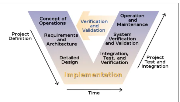
Figure 1.1 illustrates a conceptual model of the SDP used at Primavera:
Figure 1.1: V-model Software Development Process abstract diagram
V-model means Verification and Validation model. Just like the waterfall [5] model, the V-Shaped life cycle is a sequential path of execution of processes. Each phase must be completed before the next phase begins. Testing of the product is planned in parallel with a corresponding phase of development [6].
Primavera noticed that the vast majority of its products had, as target, very similar busi-ness areas. This meant that much of the busibusi-ness logic was shared by the applications developed, however, the same development process was repeated for the creation of the applications. This meant that much of the SDPs were repeated without any reuse among different applications' with similar business logic.
To address this problem, to increase development's productivity and to improve the quality of applications developed, Primavera's developed the Athena Framework. This framework allows the creation of the next line of Primavera Products and allows the SDP to be more effective. The framework contains much of the business logic's that compose Primavera
Products and allows a Business Specialist and/or Programmer to specify his application and respective services abstracting him from software architecture design and code details.
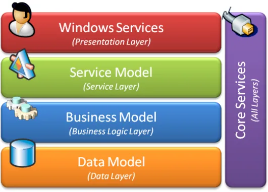
Figure 1.2 presents an High-Level architecture of the Athena Framework:
Figure 1.2: Athena Framework High Level architecture
The Athena Framework is a four layer architecture. It generates about 60% of the appli-cation's source code, data persistences structures and user interfaces. The framework will be presented in detail later in this document on Chapter 2 (State of the Art), Section 2.2 (Athena Framework).
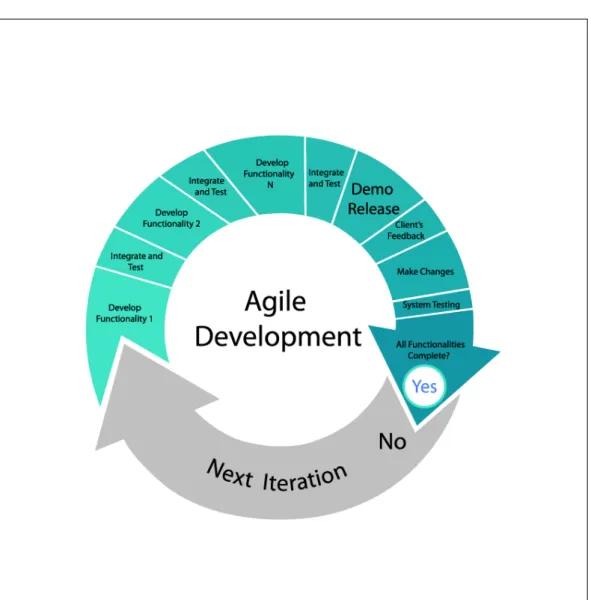
Primavera has started a process to evolve the SDP to Agile [7] based methodologies. Figure 1.3 shows a conceptual model of an Agile based SDP:
Figure 1.3: Agile Software Development Process abstract diagram
Agile software development is a group of software development methods based on itera-tive and incremental development. It promotes adapitera-tive planning, evolutionary development and delivery, a time-boxed iterative approach, and encourages rapid and flexible response to change [8].
The Athena Framework allows an Agile development process, since for each Product there are several incremental iterations and, in each iteration, there's no need to start a new de-velopment process; the Business Specialist can simply start adding functionalities to the
previous application iteration which results in an agile software development process.
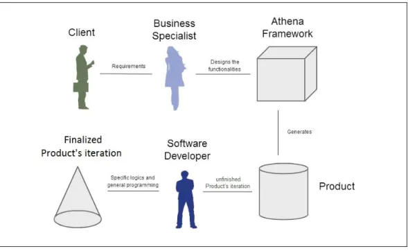
Figure 1.4 shows an abstract diagram of the development process of a Product using the Athena Framework.
Figure 1.4: Athena Framework Product Development abstract diagram
Firstly, the Client approaches the Business Specialist. Together, they define the require-ments which the business specialist will later analyse and record. Secondly, the business specialist implements the functionalities derived from the requirements by designing them on the Athena Framework designers. In most cases, the business specialist is also a soft-ware engineer but one of the features and advantages of the Athena Framework is that the person responsible for designing the application only has to be able to understand the busi-ness logic of the product that he is developing.
After the design phase ends, the Athena Framework will, automatically, generate most of the application's source code (about 60%). At this point, however, the application is not yet ready to be delivered to the Client because 40% of the application still has to be developed. The
40% includes specific business processes which, for ther complexity or specificity, need to be designed and programmed later; it also includes specific services, deployment questions and data persistence improvements and optimizations. At this phase the person reponsible for finishing the application are the programmers but the Business Specialist can also inter-vene.
After the application source code is completed, an application's iteration has been con-cluded; what is left is a potentially deployable Product which is ready and awaiting testing. The Quality Assurance (QA) Department of Primavera's Software Factory has the objective of ensuring that all Primavera products comply with the standards of Primavera's quality patterns and that they meet the customers' expectations. To ensure the functional quality of the software, two different but complementary types of testing are conducted: firstly, man-ual testing that is representative of the large part of the time and effort invested on testing, secondly, a set of very limited automatic tests of about 1.000.000(one Million) tests in each month.
1.2 Automatic Testing for the Athena Framework
The Agile development methodologies have as a main characteristic the quick change and the ability to adapt to that change. In this context, the Athena Framework allows for the SDP to be quicker and facilitates the evolution of the software, which allows for a fast adaptation to change and for it to be done with fewer costs.
However, the current test solutions of the QA Department can not keep up with the ability that the framework has to adapt to changes. It makes absolute sense to add a new test component, that allows code for testing to be automatically generated, to the Athena Framework, as the framework is able to do so for the software.
The work, which will be presented in this dessertation's document, is integrated with the Athena Framework as one of its components, and available to all applications developed
with the framework, since their creation, providing automated test capabilities in the earliest phases of the SDP. It has the capability of running tests on the application's user interface by simulating mouse and keyboard events in the application's views. The solution provides automation for 80% of the Athena applications' views, posing as a reliable tool to conduct Integration and Acceptance testing on the application.
The developed solution is able to keep up with the agile SDP and allows testers to reduce the number of manual tests done through the automation of the process, which results in greater, faster and more extensive testing, thus reducing costs and increasing the software quality.
1.3 Research Questions
In this thesis we aim at answering to the following three research questions:
1. Is it possible to automate graphical user interface software tests in
Sil-verlight interfaces?
2. Is it possible to automatically generate excel test specifications from the models of the Athena Framework?
3. Will a model-based test solution present results that will prove it to be a reliable and efective tool, available to the Quality Assurance Department of Primavera Software Factory?
1.4 Document Structure
This document is organized as follows:
Chapter 2 A state of the art review of some specific areas of software testing, code
gen-eration and the Primavera's BSS branch company name Primavera Software Factory is presented.
First the Athena Framework is presented and explained on the context what software testing is and what is it for. Then the Athena Framework is presented and explained on the context of the Primavera Software Factory.
Chapter 3 In this chapter it's given an overview of the different tools that will be available,
at the time of this report, for conducting the development and deployment of the project.
Chapter 4 This chapter describes the expected results for the project as well as the main
challenges that are expected and the project planning roadmap.
Chapter 5 In chapter 5 it's explained the decision-making process as well as the developed
Test automation component for the Athena Framework.
Chapter 6 This chapter presents an overview of the real usage Tests conducted on the
developed Solution as well the results of these Tests and the impact of the proposed Solution on the Organization.
Chapter 6 In this chapte,r the results of the developed work are discussed and the
con-cluding remarks presented. It's also given an overview of what could be the Future Work of this project.
State of the art
Summary
In this chapter a state of the art of software testing, as well as an overview of the Athena Framework will be presented. A framework developed by the company Technology - Primavera Software Factory, where the work of this dissertation is conducted, which is a subsidiary of the Primavera BSS company.
2.1 Testing
Before we survey the techniques used in software testing, let us clarify the notion of software testing [9] and why it is needed in software engineering [10]. The illustration of the test types and design techniques presented was based on [9]. The International Software Testing Qualifications Board (ISTQB) is a software testing qualification certification organization that operates internationally.
2.1.1 What is Testing
Testing consists on various activities that can take place from the beginning to the end of the software development life-cycle with the purpose of finding defects and identifying failures on the software being tested. Test activities include planning and control, choosing test conditions, designing and executing test cases, evaluating test results, reporting on the tests
and target system as well as reviewing documents (example: source code) and conducting static analysis.
Static testing includes activities such as reviews, walkthroughs or inspections, that can and are often omitted. In contrast, dynamic testing consists in the actual execution of code that will test the overall software system or a specific module (or functionality) of the same system. In this later case, the testing techniques can be used to test a software sytem that is not fully implemented. In a best case scenario the testing techniques use a set of test cases that should cover (all) the software system. Much of the dynamic testing takes place along side with the development phases so that the problems can be identified as soon as possible.
Testing, however, is not only used to find problems/bugs on the software that is being tested. Testing can be used to give a notion (to the stakeholders) about the quality of the product on a given time, which can be useful, for example, when the software development method is an Agile method [7]. In this case there are multiple cumulative releases of the product, so the tests can give a notion on whether the iteration of the unfinished product has quality to be launched, or not. So, it can be said that the main objectives of testing are finding defects, gaining confidence about the level of quality of the software, providing information for decision-making, and preventing defects.
Some common misconceptions about testing are that testing consists only of running tests cases and that testing and debugging are the same activity. As stated before, testing consists on a large set of well defined activities that can take place along all the development cycle, while debugging is the activity of finding, analysing and removing the cause of software failures. This is a development activity, done by developers.
Testing, and particularly dynamic testing, can show failures that are caused by defects. Dynamic testing is carried out by testers, and a failure is identified by comparing the expected results of test cases to the actual results produced. If expected and actual results differ, then a failure occurred. Then, the developers carry out the debugging activity to find, analyse and resolve the reported defect. After this, the cycle of testing, reporting and debugging restarts.
2.1.2 Why is Testing Necessary
Software applications are changing the way people live. Nowadays there's software in almost every aspect of people's lives, being it communications, business applications, consumer products (i.e. cars, house apparel). The majority of this software is responsible for regular people to interact with cell phones, medical equipment and social networks. It is expectable that sometimes the software doesn't behaves correctly (i.e. as it was expected) which can lead to many problems like: loss of money, productivity, time, business reputation and in same cases even injury or death.
When discussing software defects it is important to distinguish between the root of the defect and the actual consequences of it.
Software is designed by human beings, and human beings can make mistakes that lead to defects (errors, bugs) in software. If a mistake is made when analysing, designing or encoding, then, when the software is executing, it might not behave as it should doing something that was not expected or not doing anything at all, resulting in a failure.
Defects are caused by Human beings, and some of the causes may be time constraints, excessive complexity or the different technologies. Failures can be caused by Environmental conditions like radiation, magnetism or even hardware malfunctioning.
2.1.3 Test Types
As mentioned in the last chapter, there are two types of testing: static testing and dynamic testing.
• Static Testing: Refers to the test activities that do not involve the execution of code, parts of the software or the entire software. The main activity are reviews: the purpose is to find defects rather than failures, and the final product of these reviews are report documents. There are four main types of reviews: Informal Reviews , Walkthroughs, Technical Reviews and Inspections.
Static testing is often performed by testing tools. Static testing tools include tools that analyse the program's source code [11], databases, spreadsheet data [12] or program models(like UML) of the design/implementation and generate reports with the intent of finding defects. The use of tools may be useful when the software dimensions are noticeable large and it is composed of a large collection of artifacts that in other way would be extremely complex and time consuming for humans to analyse. Since static testing is not on the scope of this dissertation, it will not be discussed in detail. • Dynamic Testing: It involves the execution of source code, parts of the software
or the entire software with the objective of finding failures, i.e. giving inputs to the software and analyse if the outputs were the expected ones.
In dynamic testing the software or some of its parts are actually compiled and exe-cuted. Some of the dynamic testing methodologies are Component Testing, Integra-tion Testing, System Testing and Acceptance Testing that will be reviewed in detail in the next section on this document.
Even though dynamic and static testing are performed with complete different approaches, they are complementary and can be carried out in any of the phases of the SDP.
2.1.4 Test Levels
There are four levels of software testing [9]: Component, >> Integration, >> System, >> Acceptance.
• Component Testing: Also known as Unit testing. It aims at ensuring that each component/unit of the software being developed is valid, i.e. performs as designed/-expected.
The functionality of the individual software models, programs, objects and classes are tested in order to find defects. This testing method is done by developers, while they are developing these units/components (white-box style). Unit testing, by itself,
cannot validate an entire software but it can ensure that all blocks that compose the software work and perform as individually expected. Despite being a functional ori-ented test activity, it can also include tests to some non-functional characteristics of the software like robustness testing.
Finding a defect at this level of testing has a low impact on the development process since it can be immediately corrected by the developer and re-tested for ensuring that the same defect doesn't occur again.
• Integration Testing: Aims at searching for defects on the interaction of the different components/units of the software.
The interactions between the units, or large parts of the software system, are tested, as well as the environmental components like the operating system, file system and the interfaces between systems. This testing method is conducted by the Testers. The greater the scope of the integration, the harder it is to isolate defects to a spe-cific component, thus increasing the risk and cost on time for the Developers to find, analyse and fix the defect. In order to avoid this problem, integration testing shall be incremental, i.e. starting by testing interaction between the most atomic units/-components and systematically increase the size and scope, instead of an all-in-one approach.
It is obvious at this point that the system's architecture influences integration testing. In fact, if the designer, developer, and tester fully understand the software architec-ture, then the development process can be done in such a way that integration test is optimized and consequently more efficient.
• System Testing: The purpose of this test is to validate whether the software com-plies with the specified requirements or not.
A full system integration test is conducted by testers, to ensure that the software com-plies with the written functional and non-functional requirements, which are both of equal importance. The test environment should correspond to the target execution environment of the software, since any difference may result on defects not being
identified on the tests. The full system integration means that environment variables like the operating system, file system, software interoperability are also tested, as long as they are referenced on the Master Test Plan.
For this level of testing there must be well defined documentation on the Master Test Plan.
• Acceptance Testing: Acceptance testing establishes the system's compliance with the business requirements and whether it is acceptable for delivery or not.
The aim of this test is not to find defects on the functionalities of the software but rather to establish confidence, test specific non-functional characteristics (such as usability) and assess if the software can be deployed. It is conducted by stakeholders, mainly by the customers and the users of the system.
2.1.4.1 Test Levels and the impact of Defects
A study [13], conducted on 2002, showed that Software bugs or errors cost the U.S. econ-omy around $59.5 billion (USD) each year.
The study also found that, although all errors cannot be removed, more than a third of these costs, or an estimated $22.2 billion (USD), could be eliminated by an improved testing infrastructure that enables earlier and more effective identification and removal of software defects.
In that study, a table shows the relatice cost factors of correcting errors taking in consid-eration only where those errors are introduced and found in the SDP. Figure 2.1 shows that regardless of when an error is introduced it is always more expensive to fix it downstream in the development process.
Figure 2.1: Relative Cost Factors of correcting Failures, as a relation between in what phase the Failures were introduced and the estimated cost of correction depending on which phase they were found.
Each column on the table of the previous figure, represents a stage in the SDP, left to right from early to advanced stages. Each line also represents stages in the SDP, top to bottom from early to advanced stages.
If an error is introduced in the earliest of stages (Requirements stage) and found on that same stage, then the cost of correcting it is the factor one(1) and represents the smallest possible cost; this is, the best-case cenario.
On the other hand, if an error is introduced in the earliest of stages (Requirements stage) but is only found in the Post-product Release, then, the cost of correcting it is 30x (30 times) higher than the cost of finding and correcting it at the earliest stage (previous scenario). Finding an error that is introduced in the earliest of the stages only in the latest stages means that, possibly, all the stages of the SDP will need to be reviewed and corrected. By analysing the figure, we conclude that testing needs to be conducted as soon as possible in all the stages of the SDP.
2.1.5 Test Design Techniques
The purpose of test design techniques is to identify test conditions and test scenarios through which effective and efficient test cases can be written.
2.1.5.1 Black-box
Black-box testing is a method of software testing whise goals is to analyse the functionalities of a software, regardless of what the software does internally.
This method assumes that the software(or parts of it) being tested is a black-box that receives an input and returns an output. It can be said that black-box testing evaluates the behaviour, i.e. output of the software being tested rather than its internal functions, proce-dures and interactions.
This test method is usually applied at every level of software testing, though it is more predominant in high-level testing.
Next, an overview of some of the main black-box design techniques is given:
• Decision Table Testing
A decision table as the purpose of modelling the logic of the software being tested. Tests done with decision table techniques may be more rigorous because those tables enforce logical rigour. The tables describe multiple scenarios, i.e., multiple combina-tions of accombina-tions that can be taken under multiple condicombina-tions.
• All-Pairs Testing
Also known as Pairwise Testing in Computers Science. It's a method of software testing that, for each pair of input parameters, tests all possible discrete combinations of those parameters. This method is used to generate the smallest possible vectors of input values that allow for a set of tests to be made to the software (or a part of it) and to ensure that it's enough for the test.
• Equivalence Partitioning
Equivalence partitioning is a technique for dividing test input data into partitions from which test cases can be derived.
It is the process of taking all possible test cases and placing them into classes. One test value is picked from each class while testing. Each equivalence data class is a partition of the original input data.
By using this technique it is expected that the test cases be designed to cover every partition at least once. This technique can also be used with the output values of the tests, i.e., defining equivalence sets of output data values from which the tester can infer the actual result of the test.
• Boundary Value Analysis
This technique aims at defining values for the tests' input variables that include rep-resentative boundary values.
It is usually used in conjunction with the equivalence partitioning technique since the boundary values are defined for each one of the equivalence sets of data defined. This allows a reduction in the number of tests that are needed to test the software (or parts of it) and thus improve the testing activity.
2.1.5.2 White-box
White-box testing, also known as structural testing, is a method that aims at testing the internal functions, procedures, interactions of usually small parts of the software.
The scope of this method is not what the software does but how it does it instead. As a consequence, these methods can be better used, for example, in component testing, in which the developer tests the source code being written and can immediately correct errors in the source code implementation.
Despite being a method that aims at software implementation correctness, it cannot test unimplemented parts of it and it cannot test for defects on the requirements.
2.1.6 Test Cases
Test Cases are a set of conditions and/or variables that allow to test whether a software of parts of it are working correctly, or not.
There are two main types of test cases: • Formal Test Cases
Formal test cases are those that are written against a given requirement. In [10] it is advocated that a requirement must always allow for a test to be written against it, otherwise the requirement wouldn't be verifiable.
So by writing test cases against the requirements, one may ensure whether the ap-plication does or does not what it is supposed to do, that is, what is defined in the requirements. Despite being truth, it does not ensure that the software is free of de-fects since it only validates the functionality defined by the requirement and not the requirement itself.
Formal test cases characteristics [9]:
– Test cases should be written to test only one thing at a time. They should not
overlap or be complicated. Test cases should be 'atomic'.
– Test cases should cover both positive and negative scenarios.
– Accurate: Should have a well defined purpose.
– Traceable: Capable of being traced to requirements.
– Repeatable: Can be performed multiple times.
– Reusable: Should be able to be reused.
• Informal Test Cases
Informal test cases are written when a software, for some reason, does not have written requirements.
feel and the scope of the test cases are the accepted normal operations of software of similar classes.
2.1.7 Automated Testing
Automation helps to implement and verify best practices and organizational standards; it improves people's productivity and facilitates control of the software processes by collecting measurement data [14].
2.1.7.1 Data Driven
Data driven testing is a methodology where the data used for tests, i.e, the input values and conditions, the output values and conditions and the test environment variables and conditions can be changed by storing the variable values on tables, databases or excel files and executing the test with the data from these sources.
Data driven scripts are those application-specific scripts captured or manually coded in the automation' tools proprietary language and then modified to accommodate variable data [15].
In fact, these test scripts are nothing more then source code or specific application domain code that will actually perform the test, and that will get the data for the test to an external source, which means that the test data is not hard coded on the test script, code or program. This approach allows the reuse of the test scripts and programs.
Data Driven Features:
The data scripts contain hard coded string tokens that are used by the application that runs the script to execute the test. When this occurs, the scripts are easily broken when an application evolves [16]. The author [15] also gives an example of a data-driven script as follows:
Figure 2.2: Example of activating a server-side image map-link in a web application automa-tion tool scripting language.
In Figure 2.2 the scenario of clicking on the image identified by his 'ImageIndex' on the page identified by the 'DocumentTitle' can be identified.
The image information is hard coded on the test script this means that this script may be broken if the title of the document or the index of the image change.
2.1.7.2 Keyword Driven
Keyword Driven testing, also known as Table Driven, is a technique to develop tests as data tables using a keyword vocabulary that is independent of the test automation tool used to execute them.
This technique allows the development of an application-independent framework but should also be suitable for manual testing.
Figure(2.3) shows a test case record defined according to this technique. The test case aims to verify the value of a user ID textbox on a login page.
Figure 2.3: Keyword driven Table 1
The 3 main characteristics [15] that define a keyword-driven Automation Framework are: • Reusable Code
• Error Correction • Synchronization
Figure(2.4) shows the pseudo-code that can be used to interpret the data record from the table of Figure 2.3.
Figure 2.4: Keyword driven interpreter pseudo-code
The pseudo-code presented in Figure 2.4 executes as follows: The primary loop reads a record from the data table, performs some high-level validation on it, sets focus on the proper object for the instruction, and then routes the complete record to the appropriate component function for full processing.
Keyword driven design allows a vocabulary that can be processed by both man and machine.
Figure 2.3, that a human tester can have and allows the tester to design tests without knowing a thing about the automation tool used to execute them.
Figure 2.5: keyword driven Table record representation
2.1.7.3 Model-based Testing
Model-based testing [17] is the automatic generation of software test procedures, using models of the system requirements and behavior. It can also include executing artifacts to effectively perform software testing.
Some of the benefits of model-based testing are [18]:
• Shorter schedules, lower costs, and better quality;
• Capability to automatically generate many non-repetitive and useful tests;
• Test harness to automatically run generated tests;
• Eases the updating of test suites after requirements change;
• Capability to evaluate regression test suites.
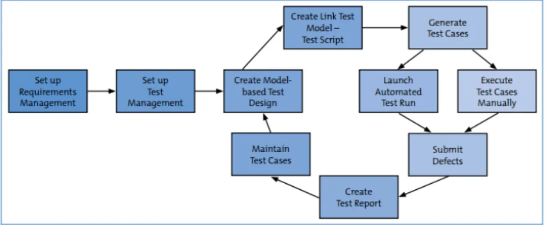
There are several steps required to successfully introduce Model Based Testing into a project [19], and Figure 2.6 presents the workflow diagram for it:
Figure 2.6: Model-based Testing workflow diagram.
[Set up requirements management] - A pre-requisite for model-based testing is that
the requirements are detailed and clear enough so that a formal model can be derived from them. This phase also involves text experts in early review to avoid problems on the test process later.
[Set up test management] - Based on the requirements, a test structure is created
con-sisting of test packages and test cases. Model-based testing may not be applicable to all requirements.
[Create model-based test design] - In this step it is important to have a proper
integra-tion with the test management tool for importing informaintegra-tion about requirements and test packages. It is important to avoid reusing models, i.e. if the code is generated from a model then there will be no changes on the generated code if the model is reused.
It is important that the designed models cover bpth test data and test sequence.
[Create links between the test model and executable test script] - The generated
tests must be linked to the model by assigning steps to GUI elements on the test definition or even creating scripts for each keyword of the test definition.
management framework. It should be possible to start test runs and store the results auto-matically from within the test management tool.
In this step, corrections to the model are made by verifying that the tests run as expected and changing the model until the tests run smoothly.
[Submit Defects] - In cases of deviation from the expected behaviour, it has to be
deter-mined whether the problem was really caused by a bug in the software or conversely by a defect in the test model.
[Create test report] - The execution logs created during the test run have to be
trans-formed into a concise test report that informs the responsible managers about the current project status. In this step, it is important to have a good integration with other tools.
[Maintain test cases] - One of the goals of model-based testing is reducing the
main-tainability cost of existing tests for new versions of the same application. For each new application's version that has to be tested, the tests have to be adapted and repeated. If the models are correctly defined, then a new application's version will only imply slight changes to the models and the re-generated test Cases will maintain their validity.
A variety of techniques/methods exists for expressing models of user/system behaviour (These techniques will not be detaild in this thesis since that is not the goal of the project):
• Decision Tables
Tables used to show sets of conditions and the actions resulting of them. • Finite State Machines
A computational model consisting of a finite number of states and transitions between those same states, possibly with accompanying actions. An example of this technique is used by the GuiSurfer tool. It extracts finit state machines, describing the GUI, from source code [11].
• Grammars
Describe the syntax of programming and other input languages. • Markov Chains (Markov process)
A discrete, stochastic process in which the probability on where the process is in a given state at a certain time depends only on the value of the immediately preceding state
• Statecharts
Behaviour diagrams specified as part of the Unified Modelling Language (UML). A statechart depicts the states that a system or component can assume, and shows the events or circumstances that cause or result from a change from one state to another.
• ClassSheets
ClassSheets [20] are a formal model to define the business logic of spreadsheet data. In [20] techniques to infer such models from spreadsheet data is presented. Such models are then used in the MDSheet(FALTA CITAR) tool.
2.2
Athena Framework
PrimaveraBSS invested many resources in creating a framework that allows the creation of the next line of Primavera products and allows the SDP to be more effective. This resulted in the creation of the Athena Framework. It allows the programmer to specify his application and respective services. The Framework generates some of the application code as well as data persistence structures and user interfaces.
2.2.1 Vision
• Support the Development of the next generation of Primavera's Products • Increase Development Productivity
• Increase Product Quality
2.2.2
Design Principles
• Declarative ProgrammingMost of the Framework behaviour can be configured, customized and modified through XML-based configuration files, which allows the customization of these behaviors with-out recompiling the software components.
• Design Patterns
The architecture implements known design patterns and best practices. • Code reuse
The re-utilization of third-party libraries to implement parts of the architecture design can boost productivity.
• Service orientation
This design orientation promotes independence between components and reduces the communication’s verbosity.
• Process orientation
The Framework's core is designed to support operations "guided" by business pro-cesses and workflows.
• Extensibility
All parts of the Framework are designed with the goal of being easily extended and customized.
• Technology independence
Such feature will allow the replacement of part of the architecture with minimal or no impact on the overall design.
2.2.3
Architecture
The High-level Architecture of the Athena Framework is divided according to the following logic layers:
Figure 2.7: Logic Layers that compose the Athena Framework High Level architecture
Thus, the Athena Framework is a four layer architecture, where the Presentation layer deals with the user interface and user experience. The Service layer deals with services that are used for the presentation layer(client) to communicate with the lower layers(server). Un-derneath the presentation layer, there's the Business Logic layer, that handles processes that compose the logic of the application. Finally, the Data layer deals with data representation and persistence.
2.2.4
Products Structure
Structure of a Product Developed with the Athena Framework.
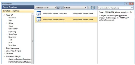
The development environment for generating a Product with this framework is the Visual Studio IDE Tool. Athena Applications Structure:
The Products developed with the Athena Framework are composed of two components: Application and Modules as it can be seen on figure 2.8 and 2.9.
Application is the project that aggregates all Modules Projects. Modules are projects that represent logical/business components of the product being created as shown on figure 2.10.
Figure 2.8: Project type Application, available with the Athena Framework integrated with the Visual Studio IDE(version 10.0.40219.1 SP1 Rel)
Figure 2.9: Project type Module, available with the Athena Framework integrated with the Visual Studio IDE(version 10.0.40219.1 SP1 Rel)
Figure 2.10: Diagram of the structure of a Product developed on the Athena Framework
2.2.5
Developing
Developing a Product with the Athena Framework.
Developing a Product with the Athena Framework is easy. After the Application's project has been created, Module's projects that express business components can be created or added to the Application's project, since the framework allows a modular and incremental component reuse as a software development approach. On the next example the designs that can be used to modulate the business logic of the created Module named "Materials" will be shown.
A Module is composed by several Visual Studio projects that were automatically gen-erated on the Module creation.
These projects are aggregated by folders(Fig. 2.11):
• 'Host'
It aggregates the project with the configuration for running the module.
• 'Client'
Holds the projects that will allow the application's presentation to be displayed on the client side.
• 'Models'
It's composed of two projects: the project that generates all database structures needed to support the business logic of the module, and the project with the designers.
• 'Server'
A set of projects that hold the configurations to treat the server side of this particular module.
• 'Tests'
Figure 2.11: Structure of a Module 'Solution' on Visual Studio IDE.
2. Entities Model Designer
The Entities Model designer allows the programmer to design the entities of this mod-ule, that is the business entities.
Figure 2.12: Entities Model Designer and ToolBox of the Module 'Materials' on the Visual Studio IDE(version 10.0.40219.1 SP1 Rel).
The most important artifacts are described as follows:
The light-brown boxes(Module Reference) allow the referentiation of other modules of the product.
The green boxes(External Entity) are references to entities of other modules in the product, models that have the corresponding module reference box created.
The blue boxes(Entity) are the actual entities of this module that can be created, as well as their attributes, and can have relations between the other entities (whether they are referenced or not).
3. User Interface Model Designer
The Interface Model designer allows the programmer to create views over the entities that he desires and also allows the default view to be edited, i.e. allows the program-mer to choose what's the view structure, attributes fields, and properties about them.
Figure 2.13: User Interface Model Designer and ToolBox of the Module 'Materials' on the Visual Studio IDE(version 10.0.40219.1 SP1 Rel).
The yellow box (Custom View) gives the possibility to define custom views for any entity if the programmer desires to do so.
4. Services Model Designer
The Service Model designer is the tool used to define the services available for any entity.
These Services that can be defined are the create, update and delete operations, so it allows for the CRUD services.
Figure 2.14: Services Model Designer and ToolBox of the Module 'Materials' on the Visual Studio IDE(version 10.0.40219.1 SP1 Rel).
5. Presentation Model Designer
In this designer the programmer defines Presentations or Reporting Views for the de-sired Views of the Entities.
Figure 2.15: Presentation Model Designer and ToolBox of the Module 'Materials' on the Visual Studio IDE(version 10.0.40219.1 SP1 Rel).
6. Lists Model Designer
It allows the programmer to create perspectives over the entities, i.e. the definition of specific views where only the selected attributes of the entity are shown. It can be seen as the definition of a preview view over the list of registers of the entity on the database.
Figure 2.16: Lists Model Designer and ToolBox of the Module 'Materials' on the Visual Studio IDE(version 10.0.40219.1 SP1 Rel).
7. Result Product
After the modulation as been done the modules can be compiled, as well as the application.
The product is finally created and when it's complied and executed, the framework, with the modulation and models of the designers, generates all the host and server services and configurations, all the business logic for the modelled entities, as well as the presentation layer for them and the data persistence.
The application can, then, be accessed through the use of a web browser and a preview of the final product can be seen in the figures 2.17 and 2.18.
Figure 2.17: Developed Product landing page in Internet Explorer(version 9.0.8112.16421) and Silverlight plugin (version 5.1.10411.0).
Figure 2.18: Developed Product home page in Internet Explorer(version 9.0.8112.16421) and Silverlight plugin (version 5.1.10411.0).
2.2.6
Domain-specific Languages
The basic idea of a Domain Specific Language (DSL) [21] is that it is a a programming language that is targeted to a particular kind of problem, rather than a general purpose language that's aimed at any kind of software issue.
DSLs are very common in computing: examples include CSS, regular expressions [22], make, rake, ant and SQL.
The Athena Framework focuses on creating and exploiting domain models with abstract representations of the knowledge about the business logic that are part of the domain of Primavera's Products.
The model designers presented on the previous chapter are no more than DSLs that were developed to take advantage of the business domain and for each a designer was built. As so, it was possible to give an abstraction about implementation details to the programmer.
Figure 2.19: Athena Module Model Designers DSL's on the Visual Studio IDE(version 10.0.40219.1 SP1 Rel).
Advantages and disadvantages of DSLs:
Advantages
• Easy to learn due to small language complexity; • Reusability;
• Productivity; • Reliability; • Optimization.
Disadvantages
• Different DSLs for different purposes;
• DSL definitions are time consuming and expensive; • Harder maintenance.
Development Tools
Summary
This section presents the tools that were used for the development of this project. We survey tools for software development, software testing, software management and infrastructures.
3.1 Software
Overview of the available software tools.
Some tools were already in use by Primavera: Visual Studio and .Net platform, White Plugin, Team Foundation Server and VMWare Server Infrastructure.
3.1.1 Development
• Microsoft Visual StudioMicrosoft Visual Studio is an Integrated Development Environment (IDE) from Mi-crosoft. With this tool it is possible to develop Windows applications, Web applica-tions, Web services and Console applications for all platforms supported by Microsoft Windows, Windows Mobile, Windows CE, .NET Framework, .NET Compact Framework and Microsoft Silverlight.
It supports many programming languages like C/C++, C#, F#, Python, Ruby, HTM-L/XHTML, Javascript and CSS. In addition to all the native features, Visual Studio allows the developer to write extensions in the form of plugins that extend the IDE capabilities.
3.1.2 Testing
• WhiteWhite is a framework for automating rich client applications based on Win32, Win-Forms, WPF, Silverlight and SWT (Java) platforms.
This framework is based on the .NET framework and it's Open Source licensed. The Automation programs that use the framework can be written in any .NET supported language, IDE and tools. White provides a rich and easy tool to test automation since it hides Microsoft's UIAutomation library, on which White is based.
• SilverlightSpy
SilverlightSpy is a visual runtime inspector for Silverlight based applications.
The application has a proprietary web browser. When loaded with a silverlight appli-cation it uses the built-in XAML explorer to give an overview of the appliappli-cation GUI controls and properties.
• UIspy
It is a tool that analyses, at runtime, the hierarchical structure, properties values and raise events of user interfaces developed with Microsoft's UIAutomation Library. It also allows the user to interact with the user interface by raising events.
3.1.3 Management
• TFSIt is a Microsoft product intended for collaborative software development projects that offers source control, data collection, reporting and project tracking.
It is available as a stand-alone software or integrated with the Visual Studio Team System.
3.2 Infrastructures
Overview of the infrastructure tools available for supporting the development. • Win2008R2-Athena
It is a VMware virtual machine. A simulation of a machine running Microsoft's Win-dows Server 2008 (64-bit) with the following emulated hardware specifications: 2 Processors, 2GB of RAM Memory, 24.00GB of Hard Disk Storage and a bridged net-work connection.
• VMWare Server Infrastructure
It is a server suite, developed and supplied by VMware, Inc, that allows to create, edit and play virtual machines. It allows remote access to the virtual machines since it uses a client-server model.
3.3
Others
Overview of some support tools. • Microsoft Excel
It is a Spreadsheet application owned and developed by Microsoft.
Microsoft Excel provides calculation, graphing tools and pivot tables functionalities. It takes part of the software bundle also developed by Microsoft named Microsoft Office.
Test Automation Component
Summary
This chapter presents the adopted strategy for the automation of testing Athena specified and generated applications. It presents the decision making process and developed artifacts of the Test Automation Component for the Athena Framework.
4.1 Objectives and Motivation
The Development Process of Primavera Software Products always followed a methodology based on Waterfall methods.
A major objective of the Athena Framework was to "agilize" the SDP of Primavera Products. As shown in Section 2.2, Chapter 2, this was achieved by abstracting the programmer from the source code complexity. Any change that the developer would make to the product using the designers would be converted by the Athena Framework in a new iteration of the product.
Since the creation of the Athena Framework, a solution of integrated Automatic Testing was always a concern and a goal for the creators of the Framework. As such, since the begining, a very limited test automation component was developed and integrated within the Athena Framework. Even though this component existed previously, it consisted on very limited Visual Studio unit tests that were only able to perform basic interface operations on
a very limited set of views. The component was never a viable solution for the Quality Assur-ance Department and his development was halted very early.
Analysing the goals that were set by the team that created the Athena Framework, the test automation component must be able to fulfill the following requirements:
• Perform integration/acceptance testing;
• Use a black-box technique, interface tests, to perform automated tests; • Be a generic solution for any product developed with the Athena Framework;
• Be a solution which adapts the tests fast and automaticaly for each new version of the product being tested.
The structure of a product developed in the Athena Framework is the following: An ap-plication is composed of several modules and each module is composed of several views. For each application there are several lines of development (i.e. latest development version, the latest released version, etc.)
There is also a Nightly Builds mechanism implemented. This means that every day, at night, all versions of all projects are compiled, wich means that every day there is a new version of each project.
One of the objectives of the Athena Framework was to "agilize" software development by using designers in which the developer could very quickly and easily make changes to each product module.
This poses a serious problem because it means that, every day, there are (potentially) differ-ent application versions from the previous day (eg: new views and forms fields, field names, etc.).
These changes in the Framework are extremely difficult to manage if the test specifications are managed manually, so an alternative to manage them automatically had to be found.
4.2
Architecture
In this section an overview of the solution's global architecture will be presented. On the next sections, each of the solution components will be presented in detail.
The architecture and components will be presented using various diagrams that abstract the many solution dimensions, which isolates the various components and interactions between them. The solution will be presented on a top-down approach.
Figure 4.1: Test Automation Framework - Components global overview
The previous diagram presents a global overview of the most important components of the solution. The solution consists on 4(four) main components:
• Test execution framework
The test execution framework corresponds to all the test projects and code for test execution on graphical user interfaces that use the Silverlight technology. The exe-cution of tests depends(necessarily) on the data sources(data-driven) within the test specifications;
The Quality Assurance Department test automation solutions already used Spread-sheets as a support for test specifications. The test cases are defined on Spreasd-sheets and can then be read by the existent test solutions. The Spreadsheet tech-nology used at Primavera is Microsoft's Excel and it will also be used in this project as a constraint. It corresponds to the set of excel files which contain the data for the tests(data-driven) and also for the test execution scripts that are no more than sequences of test cases from the excel files arranged on a business logic process sequence. Included in this component there's also the tools for automatic generation and manipulation of the excel test specifications;
• Test execution environment
There are many test execution environments. The test execution framework allows the tests to be executed in almost any computer. The requirements assuming that such computer has access to the application being tested(the application can be installed locally on the machine or through the internet network), access to the test reporting structures(email service and results database service);
• Result report
The test results are treated in two separated ways:
The test results are sent, by email, at the end of the test script execution. The results are presented to the user through a user-friendly html file with the infor-mation about the expected and actual test result for each of the test cases from the test script. The html also contains the execution and error log, as well as the context informations;
– Database
The results of the test script are stored on a central database.
Test execution framework
A central component of the test solution is the Test Execution Framework. This is the data-driven framework that will receive test specifications as an input, execute the test cases defined on the test specifications and output the results.
Figure 4.2: Test Execution Framework - Components global overview • Test execution implementation
It corresponds to source code artifacts, methods and algorithms that allow the exe-cution of tests to be conducted on Silverlight interfaces;
• Application modules' test projects
Each module of an Athena application has a test project that allows access to the designer's dsls which allows for the test specifications to be generated. Each test project also allows automated testing to be conducted on the module views;
• TestexecutionCAPP
The test execution console application is a program developed for the execution of test scripts. Test scripts are logic sequences of test cases that can or cannot represent business processes.
Test specifications
The Test specifications component aggregates all the input data for executing tests. It also includes data management tools, which allows the designed test cases to evolve along with the application's iterations.
Figure 4.3: Test specifications - Components global overview • Excel files
For each automatable view of each Athena application module, an excel file, with data for the tests of the view, exists;
• Test scripts
It corresponds to sequences of tests from the excel file that, when logically sequenced, correspond to complex business processes;
• AthenaTestSuite
It is a database which holds the information about each view's graphical user inter-face specification(controls). This database is always up to date with the most recent versions of the Athena applications;
• Excel generation tool
without any human intervention. It generates each excel file for each module's view, based on the view's graphical user interface specification, present on the AthenaTest-Suite database;
• Data management tool
It provides "find and replace" and "copy" operations between the views test specifi-cation excel files.
Test execution environment
In order to ensure testing correctness, validity and effectiveness, the environments where the tests are executed are of extreme importance. At Primavera there was already a virtu-alization environment implemented. This environment separates the developer's/tester's local environment from a staged "real cenario" environment, thus assuring testing correct-ness. Test validaty is also assured because we have complete control over the test cenarios, which means, the tester can setup a virtual machine on the network with whatever software characteristics he wants. Accordingly, testing can be effective because it is possible to cover the needed test scenarios with precision.
• Excel files
The files that contain the test cases specifications for each view;
• Test scripts
The script(s) that will be executed;
• Test execution framework
The binaries(dlls) of each of the application module's test projects and those of the test implementation projects;
• TestExecutionCAPP
The tool that will automatically execute the test script;
• Application access
The test environment must provide access to the version of the application being tested. The application may have been previously installed on the machine or it can be accessed through the network, which requires either local access to the machine where it is installed or internet access.
• VM settings
It corresponds to the operating system of the VM as well as the versions of the software installed.
Figure 4.5: Reporting component - Components global overview • results database
The results of each test script executed are stored on a database, as well as the information about the test environment;
• trx reports
After each test case(each step of the test script) has been executed, a trx extension file is produced and stored;
• html reports
After a test script has been executed, an html file is generated automatically with the most relevant information about the test results. This file is then sent by email to the test responsible;
• trxTOhtml
This tool was developed to read and compile the information of each trx file in order to generate an html file that aggregates the most relevant information about the results of a test script execution.
4.3
Excel Test Specification Generation
As mentioned before, the need to automate the generation of the test specifications arises from the fact that the Athena development environment potentially produces a new applica-tion from day to day(derived from the changes made).
The maintenance cost of the test specifications(data-driven) would be great and it may even be infeasible for temporal matters (the limit would be a day to update the specifications and automatically run tests).
Thus, the generation of specifications for data-driven testing follows a model-driven im-plementation.
To perform graphical user interface automated testing in Athena applications it is only required to know which controls are part of each view of each module of each application.
4.3.1 The Silverlight technology
Microsoft Silverlight is a powerful tool to create and deliver rich Internet applications and media experiences on the Web.
Silverlight 5 builds on the foundation of Silverlight 4 for building business applications and premium media experiences. Silverlight 5 introduces more than 40 new features, including dramatic video quality and performance improvements as well as features that improve de-veloper productivity. [23]
The interface layer of the Athena framework generates the graphical user interfaces with the user on the Silverlight technology.
From the point of view of test automation, it is important to understand how the elements of the graphical user interface of a silverlight application are structured.
Using a tool like Microsoft Inspect.exe [24], which makes use of the Microsoft UIAutomation api, the visual UIAutomation tree and information about the controls of the application can
be visualized.
The following figures show the information of a Ui Automation control tree for the Login window of an application developed in Athena with a Silverlight interface.
Figure 4.7: UI Automation tree of figures 4.6 login window
Figure 4.6 shows the login home page for an application developed in the Athena Frame-work. Its interface is comprised of several labels, text boxes, images, buttons and others. In Figure 4.7 the UIAutomation tree of the login graphical user interface can be seen, as well as detailed information about the text boxes control "Username".
• "AutomationId"
This is the most relevant property of the control from the automation stand point of view. This property will always exist and there should be a unique identifier for each control tree to be able to later identify unambiguously all controls.
• "ClassName"
This property is useful because it identifies the type of control and, consequently, which transactions/events that can be triggered.