Amplitude-Dependent Internal Friction Study of Fatigue Deterioration in Carbon Fiber
Reinforced Plastic Laminates
Yoichi Nishinoa* , Ryota Kawaguchia, Satoshi Tamaokaa, Naoki Idea
Received: September 26, 2017; Revised: February 13, 2018; Accepted: April 20, 2018
The amplitude-dependent internal friction in carbon fiber reinforced plastic (CFRP) laminates subjected
to fatigue cycling has been measured and analyzed to convert into the plastic strain of the order of 10-8
as a function of effective stress. The microplastic flow indeed occurs in the stress range three orders of magnitude lower than the failure stress, and the stress-strain curves tend to shift to a lower stress as the number of cycles increases, thus indicating a decrease in the CFRP strength. The microflow stress at
the plastic strain of 1×10⁻⁸ keeps a constant value of about 0.4 MPa in the range less than 103 cycles but
then decreases gradually, whereas the Young's modulus evaluated from the resonant frequency is almost
constant up to 104 cycles where only transverse cracks are found. Thus we can successfully detect the
onset of fatigue deterioration by means of the amplitude-dependent internal friction.
Keywords: CFRP, fatigue, amplitude-dependent internal friction, microplasticity, Young's modulus.
*e-mail: [email protected]
1. Introduction
Carbon fiber reinforced plastic (CFRP) has excellent mechanical properties such as high specific stiffness and specific strength. Since weight reduction is possible by applying CFRP, it is widely used in the transportation field, especially in the aerospace field. In general, composite
materials have been considered as fatigue insensitive because the conventional loading levels applied to components are
far too low to initiate any local damage that could induce catastrophic failure. However, CFRP shows complicated
damage behavior under tensile fatigue loading1, and the three-stage fatigue deterioration has been observed2. Fatigue damage starts very early, and in this initial loading period
(Stage I), there is generally a small drop in stiffness caused by transverse crack initiation. This early damage is followed by Stage II characterized by a very gradual degradation of stiffness, which results from coupling between transverse
cracks and interfacial debonding/cracks, and residual strength
continues to decrease throughout Stage II and into Stage III. More serious types of damage appear in Stage III, such as fiber breakage and unstable delamination growth, leading to an accelerated decline with an increasing amount of fatigue damage and finally catastrophic failure3.
In particular, the occurrence of transverse cracks is not
a direct cause of reduction in strength of the entire laminate
but is a starting point of interlaminar peeling and fiber breakage which are more serious damage1. Therefore, in
order to understand the fatigue damage behavior of the CFRP
laminates, it is important to properly evaluate the transverse
crack behavior. Ultrasonic testing is the most common non-destructive evaluation technique and is useful for detecting
such defects as delamination in layers parallel to the surface
of laminate, but is not suitable for transverse cracks and
defects related to carbon fiber due to its low resolution. Thus, the establishment of non-destructive evaluation technique of damage accumulation is required to detect the onset of fatigue deterioration.
It is known that an internal friction measurement is relatively sensitive to the variation in microstructure, for example, the formation of microcracks and crack propagation. We have
previously studied the amplitude dependence of internal friction
and microplasticity in alumina with microcracks4, carbon
fiber reinforced SiC ceramics5 and SiC whisker reinforced Al2O3 ceramics6. The amplitude-dependent internal friction
in the composites is considered to arise from fiber pull-out or microcrack propagation. In particular, the variation in the microflow stress evaluated from the amplitude-dependent internal friction agrees well with that for the fracture stress4.
Thus, this method is the most promising way to monitor
the trend in strength change during the forerunning process
of fracture in fiber reinforced ceramics or plastics. In this
study, transverse crack initiation and accumulation in the
CFRP laminates under fatigue loading has been evaluated focusing on the onset of fatigue deterioration.
2. Experimental
Carbon fiber reinforced epoxy prepreg sheets were prepared, and flat specimens of an angle-ply CFRP laminate were fablicated by a normal prepreg compression molding process: the lamination pattern of angle-ply was [60/-60/0]s. Specimens for fatigue tests were cut from the CFRP laminates to the size of 250×25×1.3 mm3. Fatigue tests were conducted under repeated tensile loading, using a fatigue testing system
that is equal to 50% of the failure stress (stress ratio, R =
0.1). The number of fatigue cycles N was changed between 102 and 106. After the fatigue tests, the samples for internal
friction measurements were cut into a rectangular shape 10 mm in width and 80 mm in length. In order to observe the fatigue defects, we employed a fluorescent penetrant inspection with the use of UV lighting, and a fluorescent dye was applied to the cross section of the samples.
Internal friction in the CFRP laminates was measured in
vacuum at room temperature by means of a free-decay method
of flexural vibration with both ends of the sample free and at a frequency between 350 and 420 Hz in the fundamental resonant mode. After steady-state vibration for more than 60 s, the driving signal was turned off and a free-decay curve measured using a data recorder, where the vibration is directly recorded against time. As a measure of internal friction, the logarithmic decrement was determined from the slope of a
tangent to the smooth envelope of the free-decay curve as
a function of the maximum strain amplitude.
3. Results
Figure 1 shows an optical micrograph of the cross section in the CFRP laminate subjected to fatigue cycling
up to N = 106. In the early stage less than N = 104, in-layer transverse cracking occurs, but in the latter stage higher than N = 105, delamination cracks with a width of around 1 mm or less are also observed at the tip of transverse
cracks. It can be seen that the development of transverse cracks in the inner (constrained) -60º plies proceeds at a higher rate than that for the outer (unconstrained) 60º plies.
In order to evaluate the mechanical properties of the CFRP laminates subjected to fatigue cycling, we measured the amplitude dependence of internal friction. Figure 3 shows
the internal friction δ plotted as a function of the maximum strain amplitude εmax in the samples with the number of cycles N = 102-106 and the undeformed sample (N = 0). When
subjected to fatigue loading up to N = 103, the amplitude-independent internal friction is almost constant and is slightly
dependent on the strain amplitude. For fatigue loading of
more than N = 105, the internal friction increases remarkably probably because of the occurrence of delamination cracks,
and becomes strongly dependent on the strain amplitude.
The amplitude-dependent internal friction is considered to
arise from the relative motion between crack faces, which
results in energy dissipation through the mechanical friction4.
4. Discussion
4.1 Conversion to stress-strain responses
According to the microplasticity theory7, we can evaluate the microplastic stress-strain responses from
the amplitude-dependent internal friction. Our analytical
approach7,8 requires only an idea about the form of hysteresis
loop in the stress-strain response. Direct observations by low-cycle fatigue tests and microplasticity experiments9,10 demonstrate that the hysteresis loop under steady-state
vibrations is always of a friction-type, namely a single closed loop with a symmetrical shape. The same type of hysteresis has been verified experimentally even for CFRP11, i.e., composites incorporating plastic laminates
as a matrix. The friction-type hysteresis is considered Figure 1. Optical micrograph of cross section in the CFRP laminate
subjected to fatigue cycling up to N = 106, as revealed by fluorescent
penetrant inspection
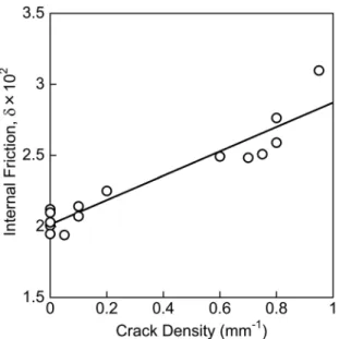
We define the crack density as the number of cracks in the outer plies of the CFRP laminates per unit length of the cross section. It is noted here that the internal friction measured under the flexural vibration is
sensitive to the presence of defects in the outer plies of
the laminates. Figure 2 shows the relation between the
amplitude-independent part of internal friction and the
crack density. It is remarked that the crack density for N
≤ 104 is less than 0.2 mm-1, and that for N ≤ 105 is larger
than 0.6 mm-1. The internal friction is found to increase
almost linearly with the crack density. Thus we believe
that fatigue damage can be detected non-destructively by
measuring the internal friction.
Figure 2. Relation between amplitude-independent internal friction
δ and crack density in CFRP laminates subjected to fatigue cycling
to be favored not only for various inorganic materials such as metals and alloys and ceramic materials12 but
also for viscoelastic solids like high-polymer materials. Procedures for analyzing the amplitude-dependent
internal friction are given in our preceding paper8. For the data analysis, the δ (εmax) curves in Figure 3 are approximated
by a power function of εmax,
(1)
where A, B and n are fitting parameters. Then the amplitude-dependent internal friction is converted to the plastic strain εp as a function of effective stress σ:
(2)
where E is the Young's modulus, and K(n) is the correction
factor for the strain distribution which is given for the flexural vibration as follows13:
(3)
where Γ is the gamma function. Eq. (2) is applicable to
evaluating the microplastic stress-strain responses from the
internal friction data expressed by Eq. (1).
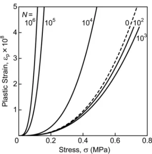
Figure 4 shows the relation between the plastic strain εp
and the effective stress σ for the CFRP laminates subjected to
fatigue cycling, corresponding to stress-strain curves in the microplastic range: the curves are obtained from the results
in Figure 3. It is noted here that the value of εp is only of
the order of 10-8 and as low as 0.1 % of the total strain. The
microplastic flow indeed occurs in the stress range three orders of magnitude lower than the failure stress, and the plastic strain increases nonlinearly with increasing stress.
There is also a general tendency for the curves to shift to a
lower stress as the number of cycles increases, thus indicating a decrease in the CFRP strength due to fatigue cycling.
Figure 3. Internal friction δ plotted as a function of maximum strain
amplitude εmax in CFRP laminates subjected to fatigue cycling of N
= 102-106 and undeformed (N = 0) sample
(
max)
A
maxnB
,
d f
=
f
+
( )
(
)
( )
n
A n
K n
E
2
2
p n
n 2
1
f
v
=
++
v
+
S X
( )
,
K n
=
2
r
n
+
3
3
C
S
n
2
+
4
X
C
S
n
+
2
3
X
Figure 4. Microplastic strain εp expressed as a function of effective
stress σ in CFRP laminates subjected to fatigue cycling of N = 102
-106 and undeformed (N = 0) sample
4.2 Comparison between microflow stress and
Young's modulus
In order to clarify the variation in the CFRP strength due to fatigue cycling, we define the microflow stress at a
constant level of the plastic strain, typically εp = 1×10⁻⁸ in
Figure 4. Figure 5 (a) shows the microflow stress σ plotted against the number of cycles N: for convenience, the data
on the undeformed sample is plotted on the axis of N = 100. The internal friction was measured for three samples at the respective number of cycles, and the average value
of the microflow stress is plotted by closed circles together with the range of variation. The microflow stress keeps almost a constant value of about 0.4 MPa in the range
less than N = 103, but decreases gradually above N = 104.
For comparison, Figure 5 (b) shows the variation in the Young's modulus E evaluated from the resonant frequency during internal friction measurements: the average value is
plotted by open circles together with the range of variation. The Young's modulus is constant in the range less than N = 104 and then decreases sharply. It is noted here that the
number of cycles required for fracture is estimated to be approximately N = 1012, which is much larger than the present
the Young's modulus drops sharply may be determined between N = 104 and 105, as shown by the dotted line, so
that the transition to Stage II can be detected very clearly. It is seen that there is no change in the Young's modulus in Stage I, while the microflow stress exhibits a decrease even in the middle of Stage I. Therefore, the Young's
modulus appears to be insensitive to transverse cracking, but
decreases sharply into Stage II where delamination cracks are observed at the tip of transverse cracks, as shown in Figure 1. It is very important to properly evaluate the onset of fatigue deterioration. Remarkably, the microflow stress
evaluated from the amplitude-dependent internal friction is so sensitive to damage accumulation that the fatigue deterioration can be detected even before the reduction in
the Young's modulus occurs.
5. Conclusions
The amplitude-independent internal friction in the
CFRP laminates subjected to fatigue cycling is found to increase almost linearly with the crack density, where
transverse cracks are mainly observed for N ≤ 104 and delamination cracks also occur for N ≤ 105. Analysis of the amplitude-dependent internal friction provides the plastic strain of the order of 10-8 as a function of effective
stress. While the Young's modulus is constant in Stage I up to N = 104 but decreases sharply into Stage II, the
microflow stress keeps a constant value of about 0.4 MPa
up to N = 103 and then decreases gradually even in the
middle of Stage I. We conclude that the microflow stress
evaluated from the amplitude-dependent internal friction is so sensitive to the accumulation of transverse cracks that the onset of fatigue deterioration can be detected
before the reduction of the Young's modulus occurs.
Further, the fatigue deterioration due to microplasticity
can be observed much earlier than macroplasticity where
the residual stress measured by tensile testing decreases
towards the end of Stage II.
6. Acknowledgment
We are grateful to H. Goto, Automobile R&D Center, Honda R&D Co., Ltd. for CFRP sample preparation and fatigue testing.
7. References
1. Harris B. Introduction to fatigue in composites: A historical review of the fatigue behaviour of fibre-reinforced plastics. In: Harris B, ed. Fatigue in Composites, Woodhead Publishing Series in Composites Science and Engineering. Oxford:
Woodhead Publishing; 2003. p. 3-35.
2. Reifsnider KL, ed. Fatigue of Composite Materials. Amsterdam:
Elsevier; 1991.
3. Van Paepegem W. Fatigue testing methods for polymer matrix composites. In: Guedes RM, ed. Creep and Fatigue in Polymer Matrix Composites. Oxford: Woodhead Publishing; 2011. p.
461-493.
4. Nishino Y, Murayama T, Asano S. Strain amplitude dependent internal friction and microplasticity in alumina with microcracks.
Philosophical Magazine A. 1992;65(5):1187-1197.
5. Ogawa H, Nishino Y, Asano S. Internal Friction and Microplasticity of Carbon-Fiber-Reinforced SiC Ceramics. Journal of the Japan Institute of Metals. 1995;59(8):788-792.
6. Ogawa H, Nishino Y, Asano S. Amplitude-Dependent Internal Friction in SiC-Whisker-Reinforced Al2O3 Ceramics. Journal
of the Japan Institute of Metals. 1996;60(4):377-381.
7. Asano S. Theory of Nonlinear Damping Due to Dislocation Hysteresis. Journal of the Physical Society of Japan.
1970;29:952-963. Figure 5. (a) Microflow stress σ at εp = 1×10⁻⁸ and (b) Young's
modulus E against the number of cycles N. The dotted line shows
the border between Stage I and II
Further, it is of interest to compare the microflow stress with the residual stress measured by tensile testing. The residual stress for FRP samples subjected to fatigue loading usually decreases towards the end of Stage II 14, but the
microflow stress exhibits a decrease during Stage I. This large difference could be due to the fact that the residual stress is substantially determined by fiber breakage, whereas the microflow stress is related to microplastic deformation caused by microcracking and fiber pull-out. Therefore, the fatigue
deterioration due to microplasticity can be detected much earlier than macroplasticity evaluated from the residual stress,
8. Nishino Y, Asano S. Determination of dislocation mobility from amplitude-dependent internal friction. Physica Status Solidi (a). 1995;151(1):83-91.
9. Lazan BJ. Damping of Materials and Members in Structural Mechanics. Oxford: Pergamon Press; 1968. p. 79-122.
10. Brown N. Observations of microplasticity. In: McMahon CJ Jr, ed. Microplasticity. New York: Interscience Publishers;
1968. p. 45-73.
11. Kim HC, Matthews FL. Hysteresis behaviour in CFRP. Journal of Physics D: Applied Physics. 1973;6(15):1755-1761.
12. Nishino Y, Ogawa H, Asano S. Mechanical hysteresis due to microplasticity in alumina with microcracks. Philosophical Magazine Letters. 1992;66(6):313-316.
13. Asano S. Analytical expressions of intrinsic internal friction based on damping data under inhomogeneous strains. Philosophical Magazine. 1974;30(5):1155-1159.
14. Adam T, Dickson RF, Jones CJ, Reiter H, Harris B. A Power Law Fatigue Damage Model for Fibre-Reinforced Plastic Laminates.