R/C Structures Strengthened With CFRP
Part II: Analysis of Shear Models
Estruturas de Concreto Reforçadas com PRFC
Parte II: Análise dos Modelos de Cisalhamento
A. L. GAMINO a [email protected]
J. L. A. O. SOUSA b [email protected]
O. L. MANZOLI c [email protected]
T. N. BITTENCOURT d [email protected]
Abstract
Resumo
This paper corresponds to the second part of a work intended to evaluate the design models of reinforced concrete structures
strength-ened with Carbon Fiber Reinforced Polymers (CFRP). The shear models analyzed correspond to the guidelines ACI 440 and ib-14, as well as more recent formulations, available in the literature. Such models were applied to eight “T” beams strengthened to shear with CFRP composites strips. Different types of carbon iber composites (sheets and laminates), from different manufacturers, available in the Brazilian market, were applied. The analyses indicate that anchorage mechanism helps increasing load capacity and ductility and that
none of the tested analytical models were capable of reproducing satisfactorily the observed behavior of the tested beams.
Keywords: carbon iber reinforced polymers, shear strengthening, experimental tests, analytical models.
Este artigo corresponde à segunda parte de trabalho visando à avaliação de modelos de projeto de estruturas de concreto armado
reforçadas com Polímeros Reforçados com Fibras de Carbono (PRFC). São avaliados modelos de cisalhamento correspondentes às recomendações ACI-440 e ib-14, além de outros modelos mais recentes, disponíveis na literatura. Esses modelos foram aplicados na análise de oito vigas “T” reforçadas ao cisalhamento com tiras de PRFC. Diferentes tipos de compósitos de ibras de carbono (tecidos e laminados) disponíveis no mercado brasileiro, de diferentes fabricantes, foram aplicados neste estudo. Os resultados obtidos indicam um ganho de capacidade resistente e ductilidade das vigas reforçadas, a partir do mecanismo de ancoragem usado nas tiras de PRFC,
e que nenhum dos modelos analíticos testados foi capaz de reproduzir satisfatoriamente o comportamento estrutural observado nos experimentos.
1. Introduction
Reinforced concrete has been established, from the decade of 1950, as the most used structural material in the world. In
-numerable researches on concrete technology, constructive
techniques and analytical and computational tools capable to provide efficient projects are dedicated to this material.
As a result more slender and optimized structures, from the safety and economical points of view, have been produced. However, these structures are more vulnerable to the dete -rioration processes (Cánovas [1]).
In the recent years, research in reinforced concrete has
drawn attention on the knowledge of the application tech-niques concerning its repair and strengthening. According to Figueiras; Juvandes [2], the growing degradation of build
-ing structures, bridges and viaducts is due mainly to ag
-ing processes, deficiencies in design and construction pro
-cedures, lack of maintenance and accidental causes (e.g.,
.earthquakes .)
The incorporation of new materials to the reinforced
con-crete, as for instance composite materials, can improve the
performance of structural elements. Those materials have already been used thousands of years ago: Egyptians used to mix straw to the clay to improve structural performance of
bricks and, seven thousand years ago, boats were built by
using tar to glue pieces of juncus.
In addition, the development of new polymeric materials, such as CFRP-Carbon Fiber Reinforced Polymer, GFRP-Glass Fiber Reinforced Polymer and AFRP-Aramid Fi -ber Reinforced Polymer has allowed a great flexibility for the strengthening techniques in reinforced concrete
struc-tures. Strengthening with polymers aims at increasing stiff
-ness, tensile, compression, fatigue and impact strength (Meier [3]).
The CFRP composites are the most indicated for strength-ening of reinforced concrete structures since they present characteristics that best fit to this structural type. Optimum mechanical performance when compared with other fibers
can be highlighted: high tensile strength, high Young´s mod
-ulus in comparison with steel, high strength to fatigue and alkaline resistance (Toutanji; Gómez [4]).
In general the composite materials are more durable than
the traditional materials. Furthermore, since they are of easy
handling and do not require heavy and expensive
frame-works, they can be used in adverse operational conditions.
Although fibers and resins used in the composite systems are relatively expensive when compared with the
tradition-al strengthening materitradition-als (concrete and steel), labor and
equipment costs for FRP systems installation are always less expensive (Figueiras; Juvandes [2]).
The objective of the this work is to investigate, from experi
-mental laboratory results, the ability of predicting the struc -tural behavior of reinforced concrete beams strengthened to shear with carbon fiber reinforced polymers (CFRP). This
work complements another publication entitled “R/C Struc
-tures Strengthened with CFRP Part I: Analysis of Flexural Models” (Gamino; Bittencourt; Sousa [5]. More details on
2. Analytical Investigation
2.1 Shear Strengthening with CFRP: International
Design Codes
2.1.1 ACI-440 [7]
The contribution in shear of iber reinforced composites is given by:
where:
α
= inclination angle of FRP; fs
= FRP strip spacing; f
d
= depth to center of gravity of FRP;A
fv= total FRP area given by:
where:
n
= total number of FRP strip;f
w
= width of FRP strip; ft
= FRP thickness;
The effective stress in FRP is:
where
E
f is the FRP Young´s modulus ande
fe is the effective strain: with:e
fu = ultimate deformation in FRP;v
k
= strain reduction factor in FRP;The effective strain can be computed by:
2.2 Shear Strengthening with CFRP: Other Models
2.2.1 Khalifa et al. [9]
The contribution in shear of iber reinforced composites is the
same expression from the ACI design code but the effective strain is given by:
The reduction factor
R
is the smallest value from the three equations:where:
W
fe = effective width of the FRP; f
ρ
= FRP geometric ratio obtained by:The effective width is: where:
e
L
= effective length of the FRP strip given by;The remaining factors can be obtained from:
2.1.2 ib-14 [8]
The contribution in shear of iber reinforced composites is given by:
where:
α
= inclination angle of FRP;θ
= shear crack angle;f
Finally the effective length can be obtained by:
2.2.2 Chen; Teng [10]
The contribution in shear of iber reinforced composites is given by:
where:
β
= inclination angle of FRP; The effective stress is:where: f
D
= distribution factor of the FRP; max, f
σ
= maximum tensile stress in the FRP;The equations for the determination of maximum tensile stress are:
The maximum anchorage length is given by:
The other factor can be obtained by:
The distribution factor of the FRP is:
2.2.3 Nollet; Chaallal; Perraton [11]
The contribution in shear of iber reinforced composites is given by:
The maximum shear stress in adhesive layer is:
The factor
k
1 can be obtained by:The factor
k
n can be obtained by:The average shear stress in adhesive layer is:
The contribution in shear of composite fabrics is given by:
The inal contribution in shear of FRP will be the smaller
V
f2.2.4 Täljsten [12]
A simple form for the determination of
V
f is giving by:where:
β
= angle between beam axis and a perpendicular line to the FRP orientation;3. Experimental Procedure
The experimental program included eight “T” beams strengthened to shear with carbon iber reinforced polymer (CFRP) with
s
f equal to15 cm (Figure 1-b) and
s
f equal to 17.5 mm (Figure 1-c).The midspan displacements were evaluated using a LVDT;
defor-mations in concrete, reinforcement steel bars and CFRP compos
-ites were evaluated using electric strain-gages (KYOWA KFG-5-120-C1-11). The beams RTC1 and RTC2, without CFRP (Figure 1-a), were used as reference for “T” beams strengthened to shear.
The remaining beams were strengthened with one CFRP layer. The beams VTC1 and VTC3 were strengthened with U-wraps
(CFRP fabric) without anchorage, VTC2 and VTC4 with U-wraps (CFRP fabric) with anchorage (Figure 2) and VTC5 with two sides
only (CFRP sheet) without anchorage.
The strain-gages distribution in the reinforcement steel bars
(bot-tom steel or stirrups) for the “T” beams can be observed in Figure 3. The data acquisition system ADS 2000 of the Lynx [13] was
used together with the programs AqDados [14] and AqDAnalysis
[15], responsible for control and coniguration of the equipment, data reading, writing, visualization and processing.
3.1 Materials
Details of the beams tested in the experimental procedure is
illus-trated in Table 1, concrete/reinforcement steel materials properties are presented in Table 2, CFRP and epoxy adhesive properties are
indicate respectively in Table 3 e 4.
The characterization tests of CFRP were evaluated in agreement
4. Experimental Results and Discussion
The results obtained from the experimental tests are summarized
in Table 5 (reference beams) and Table 6 (strengthened beams
with CFRP wraps).
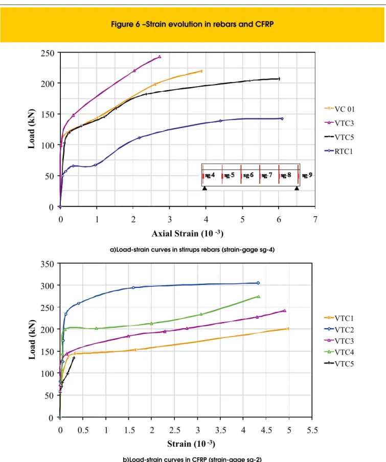
Based on the experimental results of the “T” beams strengthened to shear using CFRP composites, the following observations can be drawn: the smaller strengthened ratio has been obtained for VTC5
(CFRP sheet without anchorage, see Figure 5-a) and the largest ratio
has been obtained for beams with anchorage mechanism (see Figure
2), VTC2 (110.3%) and VTC4 (89.6%) – in these beams the failure mode found was rupture of CFRP; the stirrup strains were larger in VTC5 and VTC1, as shown in Figure 6-a – in these beams the observed rupture
was the shear mode; the behavior of the beams strengthened without anchorage was more fragile in comparison to the reference beams
cement based instead of a polymeric based grout.
Figure 7 presents the strain evolutions in the CFRP wraps for the beam VTC3. Observe that the strains in CFRP wraps
intercept-tive basis for computational simulations performed by the authors
5. Comparison of Predictions
and Experimental Results
The comparison of the theoretical results using the analytical mod-els described in this paper and the experimental results are shown
in Table 7 and 8. These results are illustrated in Figure 8.
Some safeguards are required at this point: the mechanical prop -erties of the CFRP strips used in the calculation were obtained from characterization tests (average values); the experimental
values of “Vf” were obtained from the shear capacity increase
quota of the CFRP strengthened beams; Khalifa et al. [9], Chen;
Teng [10] e Täljsten [12] models are applicable only to beams
strengthened to shear in “U” or in two sides; the computed val
-ues of “Vf” for beams VTC2 and VTC4 were performed under
the assumption that the strengthening wraps the whole section in
order to simulate the anchorage system in the junction slab/web
adopted in this work.
From the comparison between experimental and analytical results the following observations can be drawn:
a) for the beam VC 01 strengthened with CFRP fabric the Vf value found with the Nollet; Chaallal; Perraton [11] model is closer to the experimental result;
b) for the beams strengthened with CFRP with anchorage
ACI-440 [7] is closer to the experimental Vf than those predicted by
ib-14 [8];
c) for the beam VTC5 strengthened with laminate glued externally the values of “Vf” computed according to Chen; Teng [10] e Khalifa et al. [9] were higher than the experimental value due to the higher
iber area; in other words, these models seem not applicable to
structures strengthened with externally glued laminates since they
increase too much the “Vf” values, tendency that should be inves
-tigated with a larger number of tests; in this beam the values
ob-tained from ib-14 [8] and ACI-440 [7] were below the experimental value, and the value obtained from Nollet; Chaallal; Perraton [11]
has shown more appropriated; Khalifa et al. [9] and Täljsten [12]
models are not applicable to beams strengthened with laminates.
d) the predictions of ib-14 [8] have shown more conservative, fol -lowed by Khalifa et al. [9] model;
6. Conclusions
Based on the results from the experimental investigations, the fol
-lowing conclusions can be drawn:
n The technique of strengthening to shear with carbon iber reinforced polymer revealed to be very effective, especially
when anchorage system of the CFRP wraps was used. For these cases the shear capacity has been substantially
improved without signiicant changes of ductility in comparison with the original beams, not strengthened with CFRP.
n Predictions of ACI-440 [7] is suggested instead of ib-14 [8],
which has shown too conservative when compared to the experimental values.
n Although conservative in most analyses, the analytical models,
including those from international recommendations and
design codes, were not capable of properly simulating the
behavior of all beams tested in the experimental program.
7. Acknowledgments
The authors wish to express their gratitude and sincere
State (Processes 06/05843-2, 04/03049-1 and 03/01608-0) and to CNPq – Scientiic and Technological Development National Board (Processes 307051/2006-4, 303735/2008-2 and 306678/2006-3) for inancing this research work.
8. References
[01] CÁNOVAS, M.F. “Patologia e Terapia do Concreto Armado”. Trad. Maria Celeste Marcondes, Carlos Wagner F. dos Santos e Beatriz Cannabrava. São Paulo, PINI, 1998.
[02] FIGUEIRAS, J.A., JUVANDES, L.F.P., Reforço de estruturas de betão por colagem de sistemas FRP.
In: REPAR, Lisboa, 2000. Anais. Lisboa: 2000. [03] MEIER, U., Carbon Fiber – Reinforced Polymers:
Modern Materials in Bridge Engineering. Structural Engineering International, V. 1, 1992.
[04] TOUTANJI, H.A., GÓMEZ, W. Durability Characteristics
of Concrete Beams Externally Bonded with FRP
Composites Sheets. Cement and Concrete Composites, V. 19, No. 4, pp. 315-358, 1997.
[05] GAMINO, A.L., BITTENCOURT, T.N., SOUSA, J.L.A.O.
Estruturas de Concreto Reforçadas com PRFC I.
Parte I: Análise dos Modelos de Flexão. IBRACON Structures and Materials Journal, V. 2, No. 4, pp. 326-355, 2009.
[06] GAMINO, A.L., Modelagem física e computacional
de estruturas de concreto reforçadas com CFRP.
Tese de Doutorado, Escola Politécnica da Universidade de São Paulo, 259p., 2007.
[07] AMERICAN CONCRETE INSTITUTE. State of the
art report on iber reinforced plastic reinforcement for concrete structures - ACI 440R-02, 2002. [08] FEDERATION INTERNATIONAL DU BETON –
“BULLETIN 14: Externally bonded FRP reinforcement for RC structures”. Lausanne, October, 2001.
capacity of RC lexural members. Journal of Composites for Construction, V. 2, No. 4, pp. 195-203, 1998.
[10] ChEN, J.F., TENG, J.G., A shear strength model for FRP strengthened RC beams.
In: INTERNATIONAL CONFERENCE ON FIBER
REINFORCED PLASTICS FOR REINFORCED CONCRETE STRUCTURES (FRPRCS 5), Cambridge, pp. 205-214, 2001.
[11] NOLLET, M.J., ChAALLAL, O., PERRATON, D.,
Strengthening of reinforced concrete beams with externally bonded iber reinforced plastic plates: Design guidelines for shear and lexure, École de Technologie Supérieure, Montreal, Canada, pp. 692-703, 1998.
[12] TäLJSTEN, B., Strengthening concrete beams for shear with CFRP sheets. Construction and Building
Materials, V. 17, No. 1, pp. 15-26, 2003.
[13] LYNX TECNOLOGIA ELETRÔNICA LTDA. ADS 2000. Manual de usuário. São Paulo. LYNX, 2003.
[14] LYNX TECNOLOGIA ELETRÔNICA LTDA.
AqDados 7.0 - Programa de aquisição de dados.
Manual de usuário. São Paulo. LYNX, 2003.
[15] LYNX TECNOLOGIA ELETRÔNICA LTDA.
AqDAnalysis 7.0 - Programa de tratamento de sinais.
Manual de usuário. São Paulo. LYNX, 2005.
[16] AMERICAN SOCIETY FOR TESTING AND MATERIALS. Standart test method for tensile
properties of polymer matrix composite materials.
ASTM D3039, 1995.
[17] AMERICAN SOCIETY FOR TESTING AND
MATERIALS, Standart test method for tensile properties of plastics. ASTM D638, 1996.
[18] GAMINO, A.L., SOUSA, J.L.A.O., BITTENCOURT, T.N., Application of Carbon Fiber Reinforced Polymer in Strengthening to Shear R/C T Beams. In: 9TH INTERNATIONAL SYMPOSIUM ON