UAN - Underwater Acoustic Network
A. Caiti
∗, P. Felisberto
†, T. Husoy
‡, S.M. Jesus
†I. Karasalo
§R. Massimelli
¶, T.A. Reinen
kand A. Silva
† ∗ ISME, Universita di Genova, Via Opera Pia, 16145 Genova, ItalyEmail: [email protected]
† ISR, University of Algarve, 8005-139 Faro, Portugal
Email: {pfelis,sjesus,asilva}@ualg.pt
‡ Kongsberg Maritime AS, Strandpromenaden 50, 3183 Horten, Norway
Email: [email protected]
§ FOI, Gullfossgatan 6, 16490 Kista, Sweden
Email: [email protected]
¶ SELEX SI, Via Hermanda 6b, 16154 Genova, Italy
Email: [email protected]
k SINTEF, Strindvein 4, 7465 Trondheim, Norway
Email: [email protected]
Abstract—Acoustic networks are for underwater what wifi is for terrestrial networks. The ocean is a nearly perfect media for acoustic waves in which regards long range propagation but poses a number of challenges in terms of available bandwidth, Doppler spread and channel fading. These limitations originate in the physical properties of the ocean, namely its anisotropy and boundary interaction which are particularly relevant in coastal waters where acoustic propagation becomes predominantly de-pendent on seafloor and sea surface properties. The acoustic communication channel is therefore multipath dominated and time and Doppler spread variable. The problem is aggravated when involving moving receivers as for instance when attempting to establish communication with or between moving autonomous underwater vehicles. The EU-funded project UAN - Underwater Acoustic Network aims at conceiving, developing and testing at sea an innovative and operational concept for integrating in a unique communication system submerged, surface and aerial sensors with the objective of protecting off-shore and coastline critical infrastructures. UAN went through various phases, including the development of hardware and software specific components, its testing independently and then in an integrated fashion, both in the lab and at sea. This paper reports on the project concept and vision as well as on the progress of its various development phases and the results obtained herein. At the time of writing, a final project sea trial is being planned and will take place two weeks before the conference so, although here we will concentrate on the progress obtained so far, the presentation at the conference may include additional results depending on the outcome of the sea trial.
I. INTRODUCTION
Underwater acoustic communications became technologi-cally attractive with the advent of untethered autonomous underwater vehicles being able to perform complex tasks for relatively long periods of time. In the 1990s the market has seen the appearance of underwater acoustic modems capable of establishing point-to-point (P2P) communication at relatively low data rates and in optimum environmental configurations (in the vertical, at short ranges and in deep water). Incoherent communication schemes (such as those based on FSK) were used in those early days and to date still provide a reliable service in many real world applications. The
natural requirement of higher data rates has pushed the market to higher frequency ranges and to coherent communication schemes. This shift revealed the shortcomings of the actual knowledge on acoustic propagation at frequencies say above 2 khz, and the effects of random environmental fluctuations that strongly affect signal coherence in the frequency band of interest: above 10 khz. There was a large body of work carried out during the last decade devoted to improve coherent com-munications. To name just a few initiatives: effort was spent on a variety of channel diversity combiners aiming at enhancing signal-to-noise ratio by adding closely located receivers; brute force multichannel differential feedback equalizers (M-DFE) were developed for optimally matching the acoustic channel at each receiver and time-reversal based techniques were used to obtain intersymbol interference reduction. In parallel, work was devoted to understand environmental effects on the acous-tic communication signal, which may lead to fundamental results at the long run. From there, an obvious evolution would be to extend P2P communication to structured networks of underwater acoustic modems opening up a whole range of new possibilities for message transmission using, for example routing and multi-hopping in a dense network of nodes.
This paper reports the objectives and achievements ob-tained so far on the FP7-funded project Underwater Acoustic Network (UAN) launched in 2008 and aiming namely at conceiving, developing and testing at sea an innovative and operational concept for integrating in a unique communication system submerged, surface and aerial sensors with the objec-tive of protecting off-shore and coastline critical infrastruc-tures. Since submerged sensors may be either fixed or moving, the communication system is a wireless acoustic network. There are at least two factors that make this task much more challenging than it appears at first glance. One is the very harsh communication environment that forms the acoustic channel, which result in fluctuating time-Doppler spread channel im-pulse responses, making it difficult to achieve communication between simple fitted network nodes. The other is the high
spatial variability of the channel impulse response making it difficult to achieve and maintain coherent communication with a moving node even at moderate speed and without depth variation.
Since the difficulties experienced in underwater acoustic communications are ultimately related to ocean physical prop-erties, the approach taken in UAN to tackle those issues is to use prior environmental knowledge of the area of operation to feed calibrated propagation models and map the estimated communication performance in the area of interest. The per-formance map is then used to navigate the mobile nodes as much as possible in high communication probability areas so the network geometry is adapted to the environmental characteristics of the area. A second concept is to define a double data rate network so as the low data rate is used to exchange basic network messages and commands between nodes, while the high data rate is used to upload data from the nodes to shore via a unidirectional link to an array equipped access point. In the UAN context minimum low data rate means 200 bits/s while high data rate means up to 8000 bits/s, depending on node-access point distance and environmental characteristics of the area.
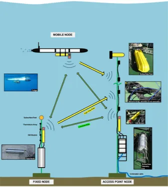
The UAN project typical scenario is composed of fixed nodes, mobile nodes and at least one access point node. These different type of nodes are depicted in Figure 1. The particularity under UAN is that communication between these various node types flow at two data rates: the low data rate is bidirectional among all nodes (green arrows) and unidirectional from the fixed and mobile nodes to the access point (yellow arrow). Such a network was deployed during an engineering test in Pianosa Island (Italy) in September 2010 and again in controlled conditions in a shallow water lagoon in Faro (Portugal) in March 2011. This paper reports the UAN concept in section II, the challenges faced for the system development and node communication setup in section III and the results obtained during deployments at sea in section IV. Project conclusions and persectives for the upcoming final project sea trial are outlined in V.
II. THEUANNETWORK CONCEPT
UAN strives from the idea that the primary requirement for successful protection of a coastal infrastructure is to possess a multisensor network reliably connected to a com-mand and control (C2) center integrating information from aerial, terrestrial, surface and underwater sensors. Although wireless connection of aerial, terrestrial and surface sensors poses, in general, no major concern, gathering information from multiple underwater sensors requires a specific approach, specially if some of those nodes are mounted on mobile platforms normally used for quick intervention in response to potential threats.
Point to point (P2P) underwater acoustic connections have been implemented since the middle 90’s, using non-coherent communication schemes which proved to be robust to en-vironmental variations and to propagation fading. However non-coherent communication is bandwidth inefficient and thus
Fig. 1. Network nodes: fixed node composed of a sensor array, a telemetry box and a modem (bottom left), a mobile node composed of a modem and an interface mounted on a underwater vehicle (upper left) and an access point node made of a receiving only vertical line array, a modem and a shore connected telemetry box (right); green and yellow arrows represent low and high data rate communications between nodes, respectively.
attain relatively modest data rates. Instead, coherent commu-nication aims at an efficient exploitation of the frequency band and assumes a time-continuous data stream with fully symbol coherence. The problem becomes then the time and Doppler spreading of the underwater acoustic channel due to the boundary interaction and due to ocean inherent variability. The concept in UAN is to go behind P2P to a network topology where multiple nodes would allow to sample the environment to a point where there would be almost always a route for an information packet to reach from any point A to B. Since in practice the required network density is seldom satisfied, the communicating route may be achieved by moving the nodes within the network to positions that are reachable, communication wyse. Therefore, the UAN network will have a variable geometry integrating fixed and mobile nodes allowing for some degree of environmental adaptivity according to the predicted communication performance given apriori environmental conditions.
In practice, due to size and energy limitations of individual nodes (specially the mobile nodes), their reach in terms of acoustic signal projection and processing is limited. In order to compensate for at least part of those limitations an access point or gateway to the wide network is located underwater as part of the network. In physical terms that node may be a buoy with surface expression or a bottom mounted device with a shore connected cable. In any of those situations it would not share the same energy and size limitations as the other nodes, being able to concentrate a higher degree of complexity
and sophistication for acoustic signal reception and processing. An underlying idea in UAN is that simple remote nodes can communicate larger amounts of data to the wide network using the access point, that concentrates the necessary complexity for signal enhancement, channel equalization and information extraction and delivery.
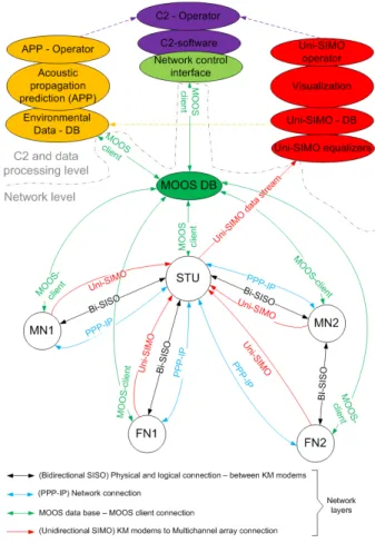
This concept may be better explained using the diagram of figure 2, which will now be explained. The physical network is represented in the lower part of the figure by five nodes, three fixed (FN1, FN2 and STU), where STU is the access point, and two mobile nodes (MN1 and MN2). The upper part of the figure represents three control systems physically located in the base station and connected to the submerged network via the STU access point. These three control systems are operator supervised and include: the acoustic prediction tool (left), the control and command (C2, middle) and the unidirectional high data rate system (right). Going from the top level layer and down the interconnection between the control level and the submerged network is made through a specific middleware called MOOS-DB. As shown through the green line MOOS-DB interacts with its MOOS clients installed on each node or application and is supported on an IP-network (cyan line). At the lower level there are the Bi-SISO link that stands for bidirectional single-input-single-output (black line) and Uni-SIMO link that stands for unidirectional single-input-multiple-output (red line). Uni-SIMO assumes that the STU access point has multiple receivers, while the individual nodes are single emitter - receiver. Bi-SIMO operates at lower rate for basic network functions, node discovery, automatic configuration, command message passing, etc, and the Uni-SIMO is used for high data rate transmission from nodes to STU access point only. The lower right corner shows an example where FN2 connects to the STU access point via a multihop Bi-SISO using mobile node MN2 that was (maybe) relocated for that purpose using a performance prediction map produced by the APP tool (left upper corner) and commanded by the C2.
An additional requirement for a network as part of a security system is to ensure a certain degree of information confiden-tiality. This is implemented in two ways: at the middleware level by using a MOOS-DB message encryption capability which provides a reasonable degree of confidentiality to the Bi-SISO connection and at the signal modulation level for the Uni-SIMO connection with the possibility of using a spread spectrum signal modulation scheme. These are not shown in figure 2.
III. UNDERWATER NETWORKING CHALLENGES
A. Physical layer: the modems
The physical layer is supported on hardware provided and specifically adapted to the task by Kongsberg. Each node car-ries a KM cNode Mini Transpoder based hardware - software setup which forms the KM TD180 transducer modem. In its KM standard Cymbal protocol mode, this modem operates with a center frequency of 25.6 kHz with variable bandwidth, transmit power and burst data rate, depending on configuration
Fig. 2. UAN network concept: five node star shaped network with three fixed nodes (FN1, FN2 and STU) and two mobile nodes(MN1,MN2), where STU is the access point; base station control via the acoustic prediction tool (left), the command and control (center) and unidirectional data transmission (right); the connection between the physical network and the control is made through the MOOS - DB middleware (center).
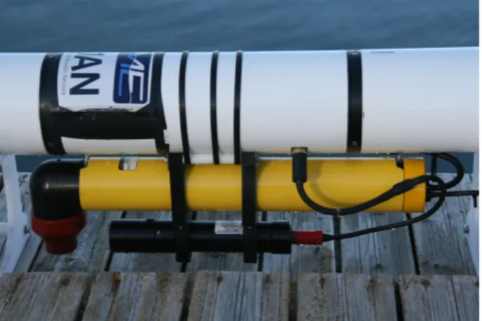
and requirements. Operation in TX/RX mode at low data rate is now possible at 1600 bps using turbo coding, and at unidirectional data rate at 8000 bps using QPSK are standard operational figures. The modem automatically detects traffic on the Bi-SISO link mode, separating heading with Cymbal protocol information from message payload that is delivered to the host via a serial port. Endurance highly depends on the TX/RX operation and may vary from 1 to 5 days. The mechanical housing is a 70cm x 9 cm diameter tube with the transducer cap on one end and the connection ports on the other. It weights approximately 3.5 kg in water, fully fitted with long life battery. Figure 3 shows the modem installed on a Folaga vehicle.
B. Performance prediction
The performance evaluation methodology developed is based on the simulation of acoustic communication in realistic underwater environments, with careful modeling of effects with significant influence on communication performance, in particular transmission loss, ambient noise, reverberation and multiple propagation paths with individual time-variable Doppler shifts due to movement of communication nodes,
Fig. 3. KM modem fitted on a Folaga vehicle (yellow tube) and an additional sensing probe (black tube below).
water surface and/or water body. A significant project mile-stone was attained with the delivery and testing of the COM-LAB communication performance predicting and evaluation tool. This software tool combines environmental, time-domain ray-based sound propagation and noise models, as well as network configuration and communication algorithms. The performance criteria are based on simulation of underwater communication using time-domain sound propagation mod-eling in realistic underwater environments. To this end the ray trace models REV3D and RAYLAB, originally developed for computation of transmission loss, were adapted to time-domain modeling with emphasis on communication applica-tions and integrated in the COMLAB package. An assessment of transmission loss modeling in the south Elba environment has been carried out showing good agreement between results of the REV3D and RAYLAB models and those obtained the PlaneRay and Bellhop codes. A detailed analysis with the PlaneRay model [1] illustrates the decomposition of the sound transmission into contributions from different propagation paths and points out that the individual paths may contribute either constructively or destructively to the received signal. Further, assessment of the fidelity of the sound propagation codes is pursued by model comparisons, benchmarking, and investigation of alternatives to the modeling of sea surface and bottom interactions [2], [3].
C. The unidirectional link
The Uni-SIMO unidirectional link is basically a P2P con-nection where the receiver end is formed by a multisensor array. Standard array processing allows for obtaining signal gain by coherently combining the sensor outputs. Coherent combining here is performed by passive time-reversal (pTR) which deconvolves array channel response by cross-correlating the incoming message with estimated channel response as given by a leading probe. In ideal conditions where the propagation media is stationary and the array spans the entire water column, pTR combining gives optimal signal enhance-ment and intersymbol interference rejection [4]. In practice this is seldom the case and the situation is aggravated when
the emitting node is moving during message transmission, thus contributing to a faster loss of coherence of the probe signal. In order to mitigate source-receiver movement impulse response frequency shifting (FS) is used, where appropriate shifts are selected for obtaining a maximum energy output - this technique is termed as FSpTR and was presented in [5]. When in presence of range - depth variation during transmissions, it was found that FSpTR has a performance comprised between 0.5 and 5 dB mean square error (MSE) gain over the non-frequency shifted version pTR, which is decisive in many situations but often requires further Doppler compensation and equalization. In UAN this was accomplished through an adaptive Decision Feedback Equalizer (DFE). The implementation of the FSpTR followed by the DFE required a new technique that accounts for phase-jump correction be-tween adjacent blocks with different frequency shifts. Results obtained on simulations, previous at sea collected data and an engineering test were presented in [6], while those obtained on UAN’10 data are shown in a companion paper at this conference [8].
D. Command and control
The latest updates in the field of security doctrine and technologies applicable to the maritime domain, together with the increased relevance of the asymmetric threat (up to the dramatic actions of our recent history) have conditioned the choice to apply the principles of Network-Centric Warfare (NCW) to its own know-how in the naval area for the development of a Harbor Protection System. In the following we will name such a system as the ”Archimede” system. This choice has determined the vision of such a system as a distributed and completely integrated system based on a NetWork Infrastructure (NWI) as backbone. This concept led to the development of a standard tactical gateway (Hermes) based on the Distributed Data Service (DDS) middleware as the mean to make heterogeneous system nodes interoperable with respect to a common tactical data domain. The use of an open architecture, through the implementation of the Hermes gateway (which allows the exchange of different messages such as tactical data, control data, videos, health status messages and engagement orders) allows the integration of different modules (such as Command & Control, Collectors, Effectors and Communication); this makes the architecture very flexible and able to be optimally instantiated for the specificities of each harbor of application.
The different families of heterogeneous system nodes, managed by a common C2, may include (but do not limit to) the following collectors: radar, sonar, acoustic barriers, opto/electronics, unmanned vehicles and others. Through a user-friendly human computer interface and its implemented system functions, the C2 module allows for the management of the network infrastructure for the activation of the distributed architecture, the remote operation of the netted collectors for the surveillance, the compilation of the common operational relevant picture for the achievement of the situational aware-ness, the direction of amplifying collectors for the assessment
of the situation, the semi-automated assessment of the threat and the remote operation of the effectors for the implementa-tion of the defensive measures.
The handling of the above mentioned heterogeneous system nodes by the C2 allows the execution of the following system operational functions: surface and subsurface surveillance, detection, classification/identification, gathering of all infor-mation and controls in a unique command and control center, tracking, counter threat and in some cases other additional features. The overall philosophy of the C2 of the extended network is to utilize the components, collectors and effectors, interfacing directly the control equipment allocated to each components. In this way all the information flow pass trough the adaptation of the gateway, as already told: the Hermes gateway.
IV. UANTESTING AND RESULTS
A. Network nodes
Two bottom fixed nodes, two AUV mounted mobile nodes and the STU access point node have been specifically devel-oped and interfaced with the KM modems described in section III-A. Each interface node is constructed around a PC104 CPU board running a tailored Linux kernel for real time message processing and running a MOOS-DB client [7]. Additional features include the gathering of environmental or acoustic data performed on the fixed nodes or on the STU. The STU in particular has a two powerful 24-bit data acquisition boards for the acoustic sensor array as well as data storage and Ethernet transmission via the electro-optical cable to the C2 operator. The Folaga AUV’s interpret the payload messages and react to commands by transmitting the relevant information to the other internal control systems. Conversely they may pack otherwise gathered information by additional sensors (such as that shown below the KM modem in figure 3) and send it either through the Bi-SISO or Uni-SIMO links to the other nodes or to the STU access point.
B. UAN’10 sea trial results
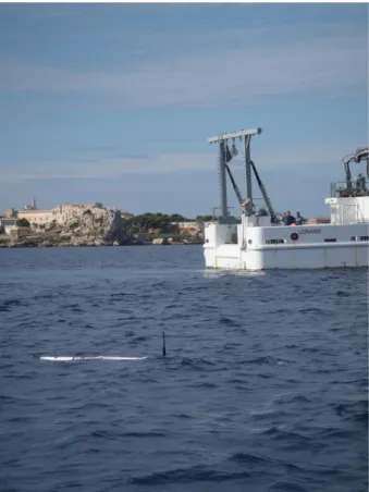
The UAN’10 sea trial took place in a shallow water area off Pianosa a small Island of the Tuscan archipelago situated approximately 10 nautical miles south of Elba Island in Italy, involving both UAN personnel, the Italian Navy ship R/V Leonardo and NURC personnel. The sea trial involved several testing including the deployment of the STU access point with a 16-hydrophone vertical line array in a water depth of 56 m, connected to the Pianosa pier via a 1 km long electro-optical cable for node power and signal. Individual nodes were deployed both from R/V Leonardo and/or from AUV’s (see Fig. 4.
1) Point-to-Point: P2P transmissions were performed in order to characterize the environment and validate equalization algorithms as well as to calibrate the acoustic performance tool COMLAB. Figure 5 shows the area bathymetry and the localization of the STU access node (marked VA) as well as the various source positions: on the Pianosa pier (lower left corner), stationary stations along the bathymetry slope,
Fig. 4. R/V Leonardo testing with Folaga vehicle in front of Pianosa Island (Italy).
marked S1 to S4, and a boat tow track along a nearly range
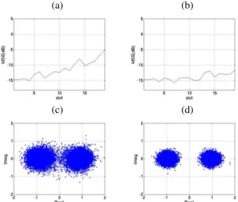
independent area. Source-receiver range varied between 100 and 700 m, source depth was about 10 m and boat speed varied from 0.1 to 1 m/s, while on drift mode or tow mode. Figure 6 shows the typical gain obtained by the FSpTR-DFE over the pTR-DFE only equalizer, where a clear enhancement of over 5 dB on MSE can be observed at the end of the 20 s data packet using the same channel probe signal for time-reversal combining drastically.
2) Network mode: A three-node network consisting of the master, and one Folaga and one static slave, was successfully set up during UAN’10. The Folaga was tested both as a relay node assisting the static node, and as a source node only (see Fig. 7). The PPP-IP connections were reliable once set up. Due to Folaga node movement during experimentation, the link quality varied. Thus, packet loss observation varied from 0 - 50%, approximately. Ping time (i.e. end-to-end delay, back-and forth) varied from 4.6 to over 80 seconds. 4.6 seconds was a typical one-hop point-to-point round trip delay (RTT). When relaying via the Folaga, the shortest RTT was about 10 seconds. If a packet was ”lost” in the water channel due to noise or collisions, or signal fade, the KM modem would attempt retransmission (at layer 2) up to three times before stopping any further attempt with that packet. Thus, an RTT could also be in order of 4 x 10 = 40 seconds. Such a case would however be very rare. More likely, any RTT larger than
Fig. 5. UAN’10 test site bathymetry with STU access point position (marked VA), stationary source positions marked S1to S4and source boat tracks along
(assumed) range independent profiles; the PIER mark on the lower left corner denotes the pier of Pianosa harbor from which test transmissions were also performed.
(a) (b)
(c) (d)
Fig. 6. P2P results with moving configuration: MSE with the pTR-DFE (a), MSE with the FSpTR-DFE (b) and the corresponding constellations without and with frequency shift in (c) and (d), respectively.
≈ 15 seconds was caused by queue backlog (new ping packets fed into the system before the former was finished, or MOOS data traffic simultaneously with ping traffic), which can happen both in the KM modem (maximum 4 packets), and in the PPP-IP driver system. The trial results were satisfactory from the point of view that PPP-IP behavior was as foreseen. However, the Pianosa test network was reduced from 5 to 3 nodes, and the available time at sea with the network up and running was limited.
C. UAN’11 network test
A second network test in controlled conditions took place in the lagoon off Faro (Portugal) in March 2011. During
Fig. 7. Node communication testing between mobile node Folaga and bottom modem in the porticiolo of Pianosa Island (Italy).
this network test a full network was setup with two Folaga and three fixed nodes, none of them with multiple sensor array since only the network features were being tested and ranges were limited within, say 100 m radius from the STU master node. All the network layers as shown on Fig. 2 where setup and successfully tested. Both Bi-SISO and Uni-SIMO messages could be transmitted and received to/from fixed or mobile nodes up to the C2 operator and visualized through the MOOS-DB (Fig.8).
Fig. 8. Command and Control (C2) screen with the pier area image (left) and with incoming / outgoing messages (right) during the network test in the Faro lagoon (Portugal).
V. CONCLUSION
Transmitting information underwater via hydro-acoustic waves faces a number of well known difficulties due to media anisotropy, boundary interaction and time-space variability. Most of these are strongly range dependent and are most difficult to tackle as frequency increases and as source and receiver are far apart and / or change their relative position during communication. All these situations are commonly encountered when dealing with multisensor systems spread
out in a shallow water area such as those dedicated to pro-tect coastal infrastructures. The project Underwater Acoustic Network (UAN) embraces those issues in the context of fully integrated IP supported wireless underwater network gathering information and receiving commands for specific intercept actions necessary for effective protection of sensitive underwater platforms or seaside infrastructures.
So far, the UAN project has successfully deployed at sea a network of nodes including both bottom fixed and vehicle mounted mobile nodes which interact to form an acoustic network. Two unique features distinguish UAN from current hydro-acoustic networks which is its ability to adapt to the local existing communication performance as conditioned by the environmental conditions and the asymmetric commu-nication data rate that takes advantage of the existence of a sophisticated multisensor access point for complex signal demodulation and equalization.
A final project sea trial aimed at integrated all the system components is planned for end of May 2011 in the Trondheim Fjord (Norway). Preliminary results obtained on that sea trial are expected to be shown at the conference.
ACKNOWLEDGMENT
The work presented in this paper was funded by the European Union Seventh Framework Program (FP7) under contract 225669. The authors also thank all the UAN team and in particular those having participated in the UAN’10 sea trial including important contributions of the Italian Navy and of the NURC team, lead by Dr. John Potter.
REFERENCES
[1] J.Hovem: Transmission loss modeling of multipath propagation. SINTEF ICT, Dec 2009.
[2] I.Karasalo, ”Prediction of acoustic communication performance in realis-tic underwater environments”, in Proceedings of the 10th European Conf. on Underwater Acoustics, Istanbul, Turkey 2010 pp. 997-1004. [3] L. Abrahamsson, S. Ivansson, ”Ray modelling including Doppler effects
for underwater communications”, in Proceedings of the 10th European Conf. on Underwater Acoustics, Istanbul, Turkey 2010 pp. 871-878. [4] A. Silva, S. Jesus and J.P. Gomes “Physics-based passive time reversal
equalizer using shallow water waveguide invariant properties”, in Proc. OCEANS’07, Vancouver (BC, Canada), October 2007.
[5] A.J. Silva, S.M. Jesus and J.P. Gomes, “Acoustic array depth and range shift compensation by using a waveguide invariant property”, in Proc. Underwater Acoustic Measurements, pp. 1315-1320, Heraklion, Greece, June 2007.
[6] U. Vilaipornwawai, A. Silva and S.M.Jesus, ”Combined adaptive time re-versal and DFE technique for time-varying underwater communications”, in Proc. 10th European Conference on Underwater Acoustics, Istanbul (Turkey), July 2010.
[7] F. Zabel, C. Martins and A. Silva “Design of a UAN node capable of high-data rate transmission”, Sea Technology, March 2011.
[8] U. Vilaipornwawai, A. Silva and S.M.Jesus, ”Underwater communications for moving source using geometry-adapted time reversal and DFE: UAN10 data”, to appear in Proc. OCEANS’11, Santander (Spain), June 2011.