A licença está disponível no em: http://creativecommons.org/licenses/by/3.0/deed.pt_BR
Repositório Institucional da Universidade de Brasília
repositorio.unb.br
Este artigo está licenciado sob uma licença Creative Commons Atribuição 3.0 Unported. Você tem direito de:
Compartilhar — copiar e redistribuir o material em qualquer suporte ou formato
Adaptar — remixar, transformar, e criar a partir do material para qualquer fim, mesmo que comercial.
De acordo com os termos seguintes:
Atribuição — Você deve dar o crédito apropriado, prover um link para a licença e indicar se mudanças foram feitas. Você deve fazê-lo em qualquer circunstância razoável, mas de maneira alguma que sugira ao licenciante a apoiar você ou o seu uso.
Sem restrições adicionais — Você não pode aplicar termos jurídicos ou medidas de caráter tecnológico que restrinjam legalmente outros de fazerem algo que a licença permita.
This article is licensed under a Creative Commons Attribution 3.0 Unported License. You are free to:
Share — copy and redistribute the material in any medium or format
Adapt — remix, transform, and build upon the material for any purpose, even commercially. Under the following terms:
Attribution — You must give appropriate credit, provide a link to the license, and indicate if changes were made. You may do so in any reasonable manner, but not in any way that suggests the licensor endorses you or your use.
No additional restrictions — You may not apply legal terms or technological measures that legally restrict others from doing anything the license permits.
1 Universidade de Brasília. Área Especial de Indústria Projeção, s/n, Gama, 72444-240, Brasília, DF, Brasil.
Dynamic response analysis of the electro-pneumatic
module of a continuous positive airway pressure in
newborns using Bond Graph modeling
Análise de resposta dinâmica do módulo eletro-pneumático da
pressão positiva contínua na via aérea modelado por Bond Graph
Suélia Siqueira Rodrigues Fleury Rosa1Universidade de Brasília suelia@unb.br
Abstract. Continuous Positive Airway Pressure is a ventilation system noninvasive complex currently applied in particular in neonatology. In this context, the parameters must have a con-trolled sett ing, since it will have an impact on the survival of premature infants with very low birth weight - which require constant control. The aim of this paper was to propose a mathematical mod-el for the mod-electro-pneumatic module of a Continu-ous Positive Airway Pressure in newborns system (Neo CPAP) with an interest in quickly check the infl uence of a particular change parameter on the performance of subsystems. The methodology used to analyze the variables was the mathemati-cal modeling by IDOV technique (validate, iden-tify, design, optimize). This approach leads to an adequate shape for obtaining the physical behav-ior and characterization of the studied system. The joint system accomplishes results that CPAP function is obtained; research has shown that, by adopting a specifi c purpose, one can create a bet-ter understanding of Assistive Technology and its parameters and how to control it.
Keywords: CPAP, modelling, Bond Graph.
Resumo. O Continuous Positive Airway Pressu-re (CPAP) é um sistema de ventilação não invasiva complexo, atualmente aplicado particularmente em neonatologia. Nesse contexto, os parâmetros devem ser controlados, pois terão um impacto sobre a so-brevivência de prematuros com muito baixo peso ao nascer – que requerem um controle constante. O objetivo deste artigo foi propor um modelo mate-mático para o Módulo de eletro-pneumate-mático de um sistema CPAP em recém-nascidos (Neo-CPAP) com o interesse em verifi car rapidamente a infl uência de uma determinada alteração de parâmetro sobre o de-sempenho dos subsistemas. A metodologia utilizada para análise das variáveis foi a da modelagem mate-mática pela técnica IDOV (validar, identifi car, proje-tar, otimizar). Tal abordagem leva a uma modelagem adequada para a obtenção do comportamento físico e da caracterização do sistema estudado. O conjunto de resultados do sistema que realiza a função CPAP foi obtido; a pesquisa mostrou que, através da ado-ção de um propósito específi co, pode-se criar uma melhor compreensão da Tecnologia Assistiva e de seus parâmetros e de como controlá-los.
Palavras-chave: CPAP, modelagem, Grafo de Liga-ção.
58 Estudos Tecnológicos em Engenharia, vol. 10, n. 2, p. 57-63, jul/dez 2014 Dynamic response analysis of the electro-pneumatic module of a continuous positive airway pressure in newborns
Introduction
The Continuous Positive Airway Pressure for Newborns (Neo-CPAP) device is used to maintain the airway at a pressure above the ambient throughout the breathing, and thus preventing the complete removal of the in-spired gas, while maintaining high stability. This technique was applied in cases of hya-line membrane disease in 1971, in which the use of this treatment was able to maintain a normal spontaneous breathing rate with ex-cellent results (Lima et al., 2004). Currently its application occurs mainly among newborns of very low weight, since this technique pro-vides increased functional residual capacity (FRC), pulmonary compliance (PC) and espe-cially the reduction of intrapulmonary devia-tion, in which an improper deviation occurs in the ventilation-perfusion ratio (V/Q), besides the reduction of oxygen diff usion (Kamper, 1999). In a study conducted by Mayor (2010), a chronology of the equipment evolution is pre-sented. The results show delimitations of char-acteristic functions of operation, handling, con-solidated and strongly validated applications (Bonassa, 2000; Borges et al., 2003; Carvalho, 2000; Carvalho e Bonassa, 2000; Postiaux, 2004). However, mathematical models of this disposi-tive are rare and they are often models that use phenomenological laws for obtaining the con-stitutive relations of the basic elements of the pneumatic system. To overcome this limitation, a study was elaborated to obtain a mathemati-cal model of the electro-pneumatic structure of the developed prototype Neo-CPAP. The the-ory used in this study is Bond Graph (BG), a graphing tool developed by H. M. Paytner in 1959 used to describe the physical interactions between physical systems, mechanical, hydrau-lic, electrical, pneumatic quantities, among oth-ers (Rodrigues, 2009). Bond Graph is meant to represent the exchange of energy among com-ponents of a physical system and the compres-sion of the interaction among the components. In general, as literature provides, pneumatic systems are fl uid systems that have multiple subsystems with non-linearities, such as com-pressibility of the air, holes, friction and losses (Garcia, 2009; Guenther et al., 2006). According to Von Linsingen (2001), a hydraulic system is a device by which an input of energy is con-verted and conditioned into useful mechani-cal energy. In this context, electro-pneumatic system of Neo-CPAP fi ts because it is a fl uid power system.
This article aimed at modeling and repre-senting the Electro-pneumatic Module for sub-systems which are analogous to mechanical equivalent circuits. Obtaining a representation of State Model -Space used in control theory that provides the ability to rapidly determine the eff ect of a given change parameters such as controllability, poles and stability in perfor-mance subsystems.
Description of the electro-pneumatic
module of Neo-CPAP
The input variables are compressed air and oxygen (O2); the output variable is the air that reaches the patient. The system works in such a way that proportional valves begin to adjust the fl ow of mixed air at the moment the equip-ment is connected. The fl ow is maintained according to the set value on the control pan-el of the equipment. The gas passing through proportional valves of compressed air and oxy-gen is directed to the mixer, homooxy-genizing the mixture. At the output of the machine there is a fl ow sensor that measures the pressure with which the gas reaches the patient. This pressure is limited according to the sett ing of the Pres-sure Positive Expiratory at the end of Phase (PEEP). Finally, any excess of gas is vented to atmosphere through the exhalation valve.
A. O
2/Compressed air channel
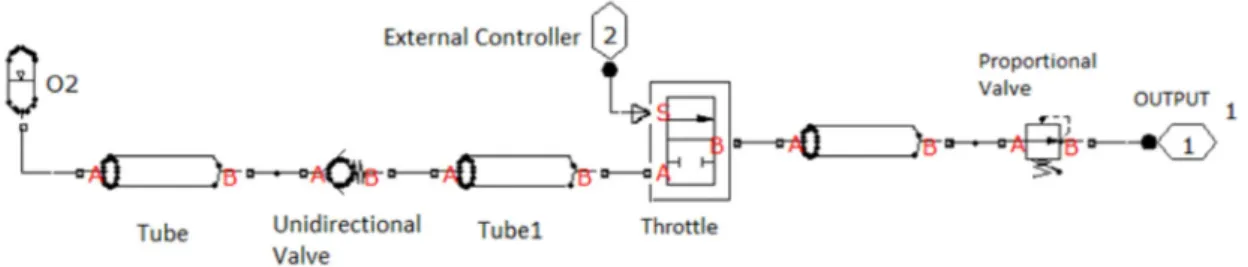
The channel for the entry of O2 corresponds to a tube connected to a one-way valve in order to allow fl ow in one direction and blocking the fl ow in the opposite direction. For this reason, there is a pressure regulating valve of oxygen, which keeps the pressure stabilized at work set value and a proportional valve that controls the fl ow of O2. The compressed air channel oper-ates similarly to the O2 channel subsystem. Fig-ure 1 shows a pneumatic circuit that comprises.
The channel of O2 with the structure of three types of valves. Its operation is based on the application of a modulated fl ow and pres-sure to the air channel of the patient.
B. Air channel of the patient
This subsystem has tubes with T-connec-tor, representing a star connection. It is com-posed by a main branch and a branch of fusion to the main application. Furthermore, there is a safety valve called PSV (Pressure Safety
and Relief Valve) that is an automatic pressure relief device to avoid excessive pressure. The PSV provides pressure relief before the sys-tem is broken up by pressure rise. It is a 3-way valve, in which the three ports are A, A1 and B. A is input, B is output and A1 controls the diff erential pressure (pc). In other words, pc is the minimum diff erential pressure valve to open A1 port and keep it open until normal pressure value is achieved.
This diff erential pressure has the control function described in Equation 1.
pc = pA – pA1 (1)
Methods
A. Simplifying hypotheses and
adopted parameters
The simplifying hypotheses are: (i) Local-ized losses of load caused by restrictions on the horizontal line, (ii) Valves with a linear behav-ior to open and close in relation to pressure, (iii) Horizontal tube, (iv) Non-turbulent fl ow, (v) Vibrations were neglected; (vi) Incompressible fl uid and constant areas; (vii) Bott lenecks in the valves only, and (viii) A linear model was adopted ignoring the nonlinearities of valves, tubes and fi tt ings. Furthermore, the Channel of Compressed Air has in its structure the same elements shown in Figure 2 (air channel of the patient, safety valve and exhalation valve). However, for this subsystem it was considered: (a) Model of fl ow following the equation of state of an ideal gas as a criterion (Equation 2) where ‘p’ is the pressure [Pa], ‘V’ is the volume [m3], ‘m’ is the mass of gas [kg]; ‘R’ is a constant that depends on the ideal gas [Nm / kg K], ‘T’ is the absolute temperature [K].
pV = mRT (2)
(b) Features of the model: (i) Model with isothermal behavior, (ii) Model of a perfect gas; (iii) Absence of condensate; (iv) Unidi-mensional fl ow, (v) Variables pressure and temperature are homogeneous in the volume.
B. Parameters
In the analysis of the parameters that com-pose the system, the basic elements of the pneumatic system are resistance (R), inertance (I) and capacitance (C). In Bond Graph theory, resistors (R) are characterized by a constitutive relationship between stress e(t) and fl ow f(t); resistors dissipate energy as the product be-tween e(t) and f(t) is always positive. In the case of pneumatic systems, the resistance is the re-lationship between pressure and output V’ (qm = fl ow). The capacitance (C), which is storage elements or energy suppliers, is characterized by the constitutive relation of stress with the integral variable displacement (q(t)). Normally, the stored potential energy is a state function, and displacement is a state variable for the ca-pacitor. In the case of pneumatic systems, the capacitance represents the compliance as a relation between mass and pressure. Finally, the inertance (I) has the ability to accumulate energy in form of kinetic energy. Moreover, the inertance relates the variable power fl ow ‘f’ to the amount of movement integral variable (Karnopp et al., 2000). Table 1 shows the pa-rameters that compose the system.
Results
To obtain the model via Bond Graph it is necessary to specify the study system based on the physical model considering simplify-ing hypotheses, inputs and outputs. The ad-opted hypotheses introduced erros in the sys-tem. The absence of condensation is necessary and suffi cient condition for the CPAP system.
60 Estudos Tecnológicos em Engenharia, vol. 10, n. 2, p. 57-63, jul/dez 2014 Dynamic response analysis of the electro-pneumatic module of a continuous positive airway pressure in newborns
The absence of condensation is a condition that results from isothermia. Moreover, it is necessary to apply the method of integrated equation by assuming unidimensional fl ow as simplifi er (Garcia, 2009). However, according to the literature, the fl ow cannot be unidimen-sional due to the viscous eff ects produced by a turbulent velocity profi le (Garcia, 2009). Thus, a future study is also needed in order to re-move these hypotheses for the purpose of im-proving the model.
The BG model of the subsystems of Figures 1 and 2 were made in the simulation software 20-sim (Rodrigues, 2009). The achievement of this system is given by the application follow-ing the change in the physical model for the analogue model. This application was sup-ported by the graphical tool Bond Graph.
The mathematical equations in the state-space model form were obtained from the analogue model (Rodrigues, 2009; Gawthrop
e Smith, 1996). The BG diagram obtained is composed by four groups of basic elements: one port passive elements (Inertance or In-ductance, Capacitance, and Resistance), two one port active elements, (Sources of Stress and Flow), two basic two port elements (Transformer and Spinner) and two junctions (1 and 0) (Rodrigues, 2009). The classifi cation of this system was considered to be a paramet-ric modeling with concentrated parameters, linear, SISO, time-invariant, continuous-time and deterministic (Garcia, 2009).
Figure 3 shows the BG diagram of the system 1 in several physical domains. The sub-system 1 corresponds to the air channel.
Mathematical modeling of the CPAP sys-tem was obtained after the preparation of BG diagram and the execution of systematic pro-cedures to obtain the equations of the system in the state-space form according to the algo-rithm for the construction of the BG.
Figure 2. System representing the air channel of the patient.
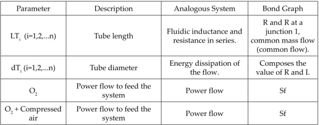
Table 1. Analog of the real variables by Bond Graph technique.
Parameter Description Analogous System Bond Graph
LTi (i=1,2,...n) Tube length Fluidic inductance and
resistance in series.
R and R at a junction 1, common mass flow
(common flow).
dTi (i=1,2,...n) Tube diameter Energy dissipation of
the flow.
Composes the value of R and I.
O2 Power flow to feed the
system Power flow Sf
O2 + Compressed air
Power flow to feed the
system Power flow Sf
Parameter Description Analogous System Bond Graph
Unidirectional valve
Allows flow in one direction and blocks it in
the opposite direction.
P is the pressure differential across the valve between the ports pA and pB allowing the
flow always in p>0.
R at a junction 1.
Throttle
Imposes a control on two hydraulic connections.
These connections correspond to the inlet opening (A), output (B) and
signal (S).
Resistance as a function of the external signal.
The formula that describes: Cd = discharge
coefficient
R at a junction 1.
Proportional valve
The input force is produced by a proportional solenoid. The force is proportional to the intensity of electric current flowing through
the solenoid.
Resistance as a function
of the external signal. R at a junction 1.
Exhalation valve Modulates the pressure
due to the flow.
Inertance having a relationship with the dynamic range of the
volume.
I at a junction 1, common flow.
Safety valve Releases the high pressure
of the system. Capacitance which has a proportional relationship with volume. C at a junction 0, common pressure (common effort). Patient Natural breathing resistance. For example,
trachea.
A variation Pp in patient pressure generates a resistance value R which
will cause a mass air flow into the lungs and
produce a variation Po in internal pressure.
R at a junction 1.
Lung Has a positive volume
pressure.
Reservoir pressure –
mass capacitance. C at a junction 1.
Table 1. Continuation.
62 Estudos Tecnológicos em Engenharia, vol. 10, n. 2, p. 57-63, jul/dez 2014 Dynamic response analysis of the electro-pneumatic module of a continuous positive airway pressure in newborns
The equation for this system is given by:
(3)
This equation represents the System of Equations in State-Space form =A.X+B.u.
Likewise, Figure 4 shows the diagram that represents the subsystem 2 in various fi elds of the BG.
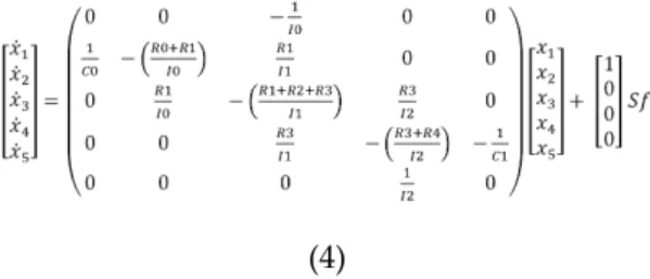
The elements that compose the BG subtem 2 are the capacitances and inertance sys-tem. The equation for this system is given by:
Figure 4. Graphical Representation of the Circuit Air System + Air Channel of the Patient.
(a)
(b)
Figure 5. (a) Step response of the system model; (b) Root locus plot of the system model.
(4)
The simulation of the system was per-formed by fi xing the elements of the tubes in constant values , which are R0, I0, I1, R2, I2, and R4. As a variation of the inlet pressure occurs from 90Pa to 25Pa, the values of R1, R3, and R5 had a relation of proportion. It means that, for a pressure of 100%, R1 = 100, R3 = 44.45 rep-resents 44.45% of the pressure and R5 = 27.78 represents 27.78% of the pressure.
According to the simulation, there is an er-ror in the system that is not stabilized at 1 Pa. Another important factor is that the response time is very high, which implies the need to introduce a controller in the system.
Conclusion
The modularity of the proposed procedure should contribute towards the use of com-plex bio-inspired systems. Finally, the pro-posed model serves as a relevant application in bio-inspired systems that demonstrates the potential benefi ts of the exact feedback linear-ization methodology, which has proved very suitable for modeling the dynamic behavior of modular systems (in this case, device med-ical) interacting with various components and nonlinearities. A code was writt en in Matlab to analyze the basic dynamics simulation of the model system, its response to the unit step input and its response in the root locus. In the system studied, the process of energy conver-sion in diff erent and equal domains occurs constantly, but with a change in the nominal value of the variable. Thus, it is necessary the use of transducer, such as valves receiving a rated voltage as the input variable, and off er a variation in gas fl ow that runs as a result. Dy-namic changes resulting from the introduction of the constants are observed in the state space matrices A of the system when compared with the system without alteration. It is noticed that the introduction of the constants in I0 element introduce a phase lag. This CPAP model may be an eff ective solution for public and private health units in order to facilitate medical care at remote health units, making it available at a relatively low cost, thus promoting healthcare in poor communities. To realize further devel-opments in bio-inspired system, it is still nec-essary to consider some specifi c aspects of this technique for the description of such systems, such as the description of nonlinear fi elds in more elements – typical of this type of system. Furthermore, new studies should explore how this technique can help in developing organic controllers.
References
BONASSA, J. 2000. Princípios básicos dos ventiladores artifi ciais. In: C.R.R. CARVALHO,
Ventilação mecânica – Básico. São Paulo, Atheneu,
vol. 1, p. 69-124.
BORGES, M.C.; VIANNA, E.S.O.; TERRA FILHO, J. 2003. Abordagem terapêutica na exarceba-ção da doença pulmonar obstrutiva crônica (DPOC). In: Simpósio de Urgências e Emer-gências Médicas, Ribeirão Preto, 2003. Anais... Ribeirão Preto, p. 36.
CARVALHO, C.R.R. 2000. Ventilação Mecânica –
Avançado. São Paulo, Atheneu, vol. 2, 621 p.
CARVALHO, C.R.R.; BONASSA, J. 2000. Ventilação
Mecânica – Básico. São Paulo, Atheneu, vol. 1,
315 p.
GARCIA, C. 2009. Modelagem e Simulação de
Proces-sos Industriais e de Sistemas Eletro-mecânicos. São
Paulo, Edusp, 678 p.
GAWTHROP, P.; SMITH, L. 1996. Metamodelling:
For bond graphs and dynamics systems. Londres,
Prentice Hall International, 317 p.
GUENTHER, R.; PERONDI, E.R.; VALDIERO, A.C. 2006. Cascade controlled pneumatic positioning system with LuGre model based friction com-pensation. Journal of the Brazilian Society of
Me-chanical Sciences and Engineering, 28(1):48-57. h t t p : / / d x . d o i . o r g / 1 0 . 1 5 9 0 / S 1 6 7 8
-58782006000100006
KAMPER, J. 1999. Early nasal continuous positive airway pressure and minimal handling in the treatment of very-low-birth-weight infants.
Bio-logy of the Neonate, 76(1):22-28. htt p://dx.doi.org/10.1159/000047043
KARNOPP, D.; MARGOLIS, D.L.; ROSENBERG, R.C. 2000. System Dynamics: Modeling and
Simu-lation of Mechatronic Systems. New York,
Hori-zon, 636 p.
LIMA, M.R.O.; de GUSMÃO FREIRE, A.L.; DE AN-DRADE, L.B.; SANTOS, L.G. 2004. Comparação dos níveis de pressão positiva contínua nas vias aéreas através de dois sistemas. Jornal de
Pedia-tria, 80(5):401-406.
htt p://dx.doi.org/10.2223/JPED.1225
MAYOR, J.T. 2010. Sistema de reabilitação pulmonar
por pressão positiva intermitente – SRPPPI.
Curiti-ba, PR. Dissertação de Mestrado. Universidade Tecnológica Federal do Paraná, 501 p.
POSTIAUX, G. 2004. Fisioterapia respiratória
pediátri-ca: O Tratamento Guiado por Ausculta Pulmonar. 2ª
ed., Porto Alegre, Artmed, 499 p.
RODRIGUES, S.S.F.R. 2009. Modelagem Dinâmica
para Controle de uma Serra Automática Utilizada em Cirurgias Ortopédicas. São Paulo, Blucher, 192 p.
VON LINSINGEN, I. 2001. Fundamentos de Sistemas
Hidráulicos. Florianópolis, Edufsc, 602 p.
Submetido: 22/06/2014 Aceito: 16/04/2015