UNIVERSIDADE DE ´
EVORA
ESCOLA DE CIˆENCIAS E TECNOLOGIA DEPARTAMENTO DE INFORM´ATICA
A 3D Web Interface for Plastic Surgery
Simulation
Jos´e Lu´ıs Pina Rolo
Orienta¸c˜ao: Pedro Salgueiro e Salvador Abreu
Mestrado em Engenharia Inform´atica
Disserta¸c˜ao
´
UNIVERSIDADE DE ´
EVORA
ESCOLA DE CIˆENCIAS E TECNOLOGIA DEPARTAMENTO DE INFORM´ATICA
A 3D Web Interface for Plastic Surgery
Simulation
Jos´e Lu´ıs Pina Rolo
Orienta¸c˜ao: Pedro Salgueiro e Salvador Abreu
Mestrado em Engenharia Inform´atica
Disserta¸c˜ao
´
Abstract
In the Plastic Surgery domain, one of the most important things to know before the surgery takes place is the impact of the incisions made in the aesthetic aspect and in the patient comfort. Breast reduction surgery is not an exception, since it is a very sensitive procedure that may cause functional and aesthetic problems to the patient after the surgery. The work described in this thesis presents a web interface for breast reduction surgeries simulation based on a research project that developed a mathematical approach to model the women breast [21, 19]. This research also developed a set of computer tools, which are the basis for the work presented in this thesis.
In this thesis we present an interactive tool to simulate breast reduction surgeries, pro-viding a simple interface that allows an intuitive planning of real surgeries. It is designed for surgeons to simulate all aspects related to breast reduction before performing the real surgery.
Interface Web 3D para Simula¸
c˜
ao de Cirurgias Pl´
asticas
Sum´
ario
No dom´ınio da cirurgia pl´astica, um dos aspetos mais importantes a saber antes da cirurgia,
´e o impacto das incis˜oes feitas no aspecto e no conforto do paciente. A cirurgia de redu¸c˜ao
mam´aria n˜ao ´e uma exce¸c˜ao, dado que ´e um processo muito delicado que poder´a causar
problemas est´eticos e funcionais ao paciente depois da cirurgia.
O trabalho descrito nesta tese apresenta uma interface web para simula¸c˜ao de cirurgias de
redu¸c˜ao mam´aria, baseado num projeto de investiga¸c˜ao ainda em desenvolvimento, que
desenvolveu uma abordagem matem´atica para modelar a mama da mulher [21, 19]. Esta
investiga¸c˜ao tamb´em desenvolveu um conjunto de ferramentas inform´aticas, que s˜ao a base
do trabalho apresentado nesta tese.
Esta tese apresenta uma ferramenta interativa para a simula¸c˜ao de cirurgias de redu¸c˜ao
mam´aria, contendo uma interface simples que permite aos cirurgi˜oes fazer um planeamento
das cirurgias reais de uma forma intuitiva. Foi desenhada de modo a simular todos os
aspectos relacionados com a cirurgia de redu¸c˜ao mam´aria antes da cirurgia real.
Acknowledgements
I would like to thank my parents for the support and stability needed during the devel-opment of my master thesis. Without their assistance this work would not have been possible.
I also thank to my supervisors, Prof. Pedro Salgueiro and Prof. Salvador Abreu, the new ideas and for always providing alternative solutions to address the problems occurred during this work, encouraging me to overcome the problems. Without their support, motivation and availability, it would be impossible to achieve the work described in this thesis.
I am also grateful to the members of the VAPS project, for providing the knowledge and the tools needed to understand the operation of the simulation software and the procedures of a real surgery. I specially thank to Dr. Igor Vasilevskiy the medical feedback during the development and his precious contribution for this thesis.
Finally I want to acknowledge Funda¸c˜ao para a Ciˆencia e a Tecnologia (FCT) the research
grant (EXPL/MAT-NAN/0606/2013) inside the VAPS project that conduce to the work described in this thesis.
Acronyms
API Application Programming Interface
CAD Computer-Aided Design DOM Document Object Model FVLib Finite Volumes Library
GIS Geographic Information System
Gmsh G mesh
HTML5 Hypertext Markup Language, version 5
OpenGLES2.0 Open Graphics Library for Embedded Systems, version 2.0 RGB Red, Green and Blue
SVG Scalable Vector Graphics
VAPS Variational Approach to Plastic Surgery VRML Virtual Reality Modeling Language WebGL Web Graphics Library
X3D Extensible 3D Graphics
X3DOM Extensible 3D Graphics based on a Document Object Model XML Extensible Markup Language
Contents
Abstract i
Sum´ario iii
Contents xii
List of Figures xiv
List of Tables xv
1 Introduction 1
1.1 Breast Reduction Surgery . . . 2
1.2 Breast Modeling Simulation . . . 3
1.3 Motivation . . . 3
2 State of the Art 5 2.1 Surgery Simulation . . . 5
2.2 Native Application vs Web Application . . . 6
2.3 Interactive Web Applications . . . 7
2.3.1 Web based Interactive 3D Graphics . . . 7
2.3.2 Dynamic Geometric Diagrams . . . 8
2.4 Conclusions . . . 9
3 Breast Reduction Surgery Simulation 11 3.1 Introduction . . . 11
3.2 Numerical Simulation Software . . . 12
3.2.1 Global Parameters File . . . 13 xi
xii CONTENTS 3.3 Breast Parametrization . . . 15 3.3.1 Components . . . 16 3.4 Surgery Simulation . . . 16 3.5 Displacement Process . . . 17 3.6 Auxiliary Tools . . . 18 3.6.1 Gmsh File Format . . . 19
3.6.2 FVLib XML File Format . . . 22
3.7 Conclusions . . . 24
4 Web Application for Breast Reduction Simulation 25 4.1 Introduction . . . 25
4.1.1 Web Application Architecture . . . 26
4.1.2 Web Application Development . . . 27
4.2 Automating the Simulation Process . . . 29
4.2.1 X3D Converters . . . 32
4.3 Web Interface . . . 35
4.3.1 First Step - Defining Breast Geometry . . . 36
4.3.2 Second Step - Surgery Simulation . . . 41
4.3.3 Third Step - Gravity Simulation . . . 41
4.4 Conclusions . . . 42 5 Overall Evaluation 43 5.1 Introduction . . . 43 5.2 Qualitative Evaluation . . . 44 5.3 Simulation Performance . . . 44 5.4 Medical Evaluation . . . 46 5.5 Conclusions . . . 48
6 Conclusions and Future Work 51 6.1 Assessment . . . 51
6.2 Future Work . . . 52
Bibliographic References 58
List of Figures
1.1 Breast reduction surgery. . . 2
2.1 Graphic technologies in HTML5. Retrieved from [16]. . . 8
2.2 Euler line theorem represented with JSXGraph. . . 9
3.1 Overall structure of Simulation Software. . . 12
3.2 Breast Geometry . . . 15
3.3 Gmsh rendering . . . 16
3.4 Gmsh rendering of the breast after the surgery . . . 17
3.5 Gmsh rendering of the breast after the Displacement Process . . . 18
3.6 Simple Cube made with Gmsh . . . 20
4.1 Web Application Architecture . . . 27
4.2 Architecture of the first step. . . 30
4.3 Architecture of the second step. . . 31
4.4 Architecture of the third step. . . 32
4.5 3D representation of a cube . . . 35
4.6 Anatomical Planes. Retrieved from [29, page: 34] . . . 36
4.7 Screenshot of the first step of simulation. . . 37
4.8 Screenshot of the geometric diagram. . . 39
4.9 Suture Plane Angle (P) representation. . . 40
4.10 Angle representation problem. . . 40
4.11 Screenshot of the second step of simulation. . . 41
4.12 Screenshot of the third step of simulation. . . 42 xiii
List of Tables
4.1 Predefined gravity vectors. . . 42
5.1 Description of used machines . . . 45
5.2 Execution times using different meshes and machines. . . 46
Chapter 1
Introduction
This chapter presents an Introduction to the work presented in this thesis, introducing the breast reduction surgeries topic as well as the motivation for doing this work.
All surgical procedures have their own associated risks for the patient health, so all surg-eries must be planned in detail, in order to minimize the risks. In the last years the software dedicated to health care increased, introducing high realism features that helps health professionals to prepare their procedures [19]. There are some kinds of software dedicated to the health professionals, such as augmented reality surgery software that helps the surgeon to interact with the human body through specific surgical tools [32, 34]. Among the health related software, there is also a category dedicated to the mathematical simulation of human organs like the heart [35, 31], liver [42] or skeleton [30].
With regard to surgical procedures, there are also some studies on numerical simulations that predict the final result of specific kinds of surgeries before the real surgery takes place, reducing the patient risks, such as the works presented in [19, 22, 23]. More specifically, the breast reduction simulation is an important tool to prevent common surgery mistakes, related with the breast aesthetic aspect after the surgery and the patient comfort. The main advantage of using a surgery simulation to plan a real surgery is that sur-geons can immediately view the consequences of a specific parameter and try another parametrization as many times as necessary, in order to achieve a good result. Without the simulation, the surgeon has only one chance to do the right parametrization. This type of simulation is particularly important on breast reduction surgeries, since the post-surgery breast shape is a very important aspect for the patient, and a simple error on the incisions can have a huge impact in the final result. With a simulation tool, doctor and
2 CHAPTER 1. INTRODUCTION patient can plan the surgery together, and if all goes well there will be no problems to solve in the post-surgery [21, 19].
Breast modeling is an active field of research, with works on aesthetic surgery [19] and medical imaging analysis [17]. Although the active research in this field, the modeling of an adequate breast model has not been reached yet [21].
The work described in this thesis is based on the research project Variational Approach to Plastic Surgery (VAPS) (EXPL/MAT-NAN/0606/2013), a joint project of Universidade
do Minho and Universidade de ´Evora. The work presented in this thesis was made in
the context of a research grant funded by this project, and the development process was closely monitored by all project members.
The researchers of Universidade do Minho developed a software that simulates the breast reduction surgeries, based on mathematical models of the women breast. The work related with this simulation software are published in [21] and [19].
The main goal of the work described along this thesis was the development of a 3D web interface based on the existing numerical surgery simulation software for breast reduction surgeries, so that surgeons can use it to prepare their surgeries more accurately and with less risk for the patient. Also important, the interface should be intuitive so that surgeons can use it without any special computer skills. With this approach, surgeons can plan their surgeries virtually in any device with a modern browser, allowing the interaction with a 3D breast model in real-time.
1.1
Breast Reduction Surgery
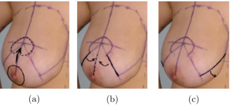
One of the methods used by surgeons to perform breast reduction surgeries consists of several steps. In first place, the nipple is placed in a new position and the breast is incised by two plans orthogonal to the chest and by an oblique plan(Fig. 1.1a). Next, the tissues incised by the two orthogonal plans are sutured to each other(Fig. 1.1b). After that, the tissues incised by the oblique plan are sutured to the chest(Fig. 1.1c)[21]. The work described in this thesis is based on a numerical simulation software that simulates this surgery procedure.
(a) (b) (c)
1.2. BREAST MODELING SIMULATION 3
1.2
Breast Modeling Simulation
Currently, there are several mathematical approaches to model soft tissues of the breast [24, 25, 17, 22, 21], but the development of an adequate breast model is still an unsolved mathematical problem. The work described along this thesis is based on a numerical approach for modeling the breast[21]. Although the model is of low precision, it was verified by the authors that it can be used to identify the most common errors on this type of surgery, allowing surgeons to avoid them.[21]
This model considers the breast tissue as a hyperelastic material. Although most soft tissues are incompressible, it was assumed that the breast is a compressible Neo-Hookean material.[21]
The breast is formed by several types of tissues but its elastic properties cannot be deduced from the elastic properties of the tissues that forms it. Another important aspect is the skin that presents different properties from the other tissues of the breast, and therefore must be modeled differently. The breast tissue is modeled using three dimensional elements and the skin is modeled using only two dimensional elements. The breast skin has the function of containing the jelly-like breast tissue, so it is a very important aspect to understand and forecast the results of breast reduction surgery. The breast also has the so called Chassaignac’s space, that is responsible for the connection between the breast and chest, playing a special role in the breast mobility. The Chassaignac’s space is modeled as mass-spring system [21].
1.3
Motivation
There are many risks associated with breast reduction surgery, including the patient com-fort and the aesthetic aspects of the breast after surgery. The simulation software for breast reduction surgery used in this work reduces the risks through a numerical simu-lation of the three main steps of the real surgery, namely: the pre-surgery process when the surgeon defines the location of the incisions; the surgery process including the incision and suturing steps; and the post-surgery that simulates the breast after the surgery under a gravity field to be as faithful as possible to reality. This enables surgeons to evaluate the breast shape before the real surgery takes place, preventing complex problems that might occur and avoid corrective surgeries to fix the breast shape. However, to use these numerical simulation software, surgeons must have programming skills, which is hard to find in health care professionals.
At the time, there is no tool that solves this problem in a simple and interactive way that surgeons can use in a daily basis. To address this problem, we decided to build an interface with the best of the both worlds. This interface must be easy to use by surgeons, sufficiently clean and organized to retain the user focus and the most important aspect,
4 CHAPTER 1. INTRODUCTION it must have a faithful viewing mechanism that allows surgeons to have a good feedback about the consequences of a set of parameters.
Throughout this thesis, the bridge between plastic surgeons and complex mathematical simulations on plastic surgery will be established with an interface that presents the evo-lution of a 3D breast model, during the entire surgery simulation process.
Chapter 2
State of the Art
This chapter introduces the State of the Art related to the work described in this thesis. First we present a survey on surgery simulation systems and then we present the actual paradigms related to web application and it’s interactive content in the browser.
2.1
Surgery Simulation
In the domain of surgery simulations, there are some systems that allow the simulation of a variety of medical interventions, such as laparoscopic procedures, cardiovascular surgeries, plastic surgeries and others. However, many of them are training platforms that surgeons use to practice the complex procedures of surgeries, like Epona Medical [4] and SimSurgery tools [11].
Surgery simulation is an active field of research, studying different approaches to the simulation of human organs like the heart [35, 31, 33], the liver [42, 26] or the skeleton [30,
20]. Some of the mentioned works are based on a physics system that simulates the
human body, while others are based only on computer software based on mathematical approaches.
In the case of plastic surgeries, training platforms are an important tool for surgeons, but that is not enough, due the fact that they don’t take into account the aesthetic aspects and the patient comfort after the surgery.
There are tools that simulate the physical aspect after the surgery, namely Vectra XT 3D [13], that is an imaging solution with a surgery simulator software and Crisalix [3], a
6 CHAPTER 2. STATE OF THE ART tool to be used mainly by patients in order to understand the impact of a given surgery. Usually these tools are only qualitative, i.e.: they don’t add relevant information for the surgery. The Vectra XT 3D is the only tool that supports breast lift and there is no tool that supports breast reduction, possibly due the fact of breast augmentation and lift surgeries having more commercial potential than breast reduction surgeries, which are mainly used to solve patient problems, despite of the improvement of the women aesthetic aspect. The main difference between breast lift and breast reduction surgery is the amount of tissue removed, while in breast lift only the skin is removed, in breast reduction both skin and tissue are removed[2].
2.2
Native Application vs Web Application
A local application is very different from a web application due to the environment in which they operate, since a local application is made for a specific device or group of devices and has to be installed on the device while a web application executes directly inside a web browser without the need of additional software.
Nowadays we can find many examples of web applications over the Internet, such as Google Docs [5], which is a productivity suite based on browser or Photopea [8] which is a web based photo editor. The main differences that distinguish a normal website from a web application are not consensual, however a web application is always compared to a normal software that as the particularity of running in a browser.
Regardless to the Internet connection, although a web application can be used offline, this kind of usage is very limited because there is no connection between client and server, so, in the most cases an Internet connection is a required feature. A local application can also use an Internet connection, but it’s not a requirement to perform their main tasks. Other important aspect is the updating process, while a local application must download their updates, which involves some waiting time by the user, in a web application the user just has to refresh the browser page and the application is updated.
One of the problems of web applications is the performance, since most of them don’t execute any tasks in the client device and there is always a delay due the communication between client and server. However, with HTML5, web developers can take advantage of client hardware without any kind of browser plugins, which it was not possible before HTML5. This is a great feature, as it solves most performance problems related to the web applications. In fact, HTML5 is the major driver of web applications, mostly due the limitations of the previous HTML standard. 3D applications can also benefit from the use of HTML5, which introduces Web Graphics Library (WebGL), a 3D rendering API for
the web, based on OpenGL ES 2.0. [7] This feature opens the doors of the web to theR
2.3. INTERACTIVE WEB APPLICATIONS 7
2.3
Interactive Web Applications
Due the changes introduced by HTML5, the Web is becoming more capable to do things which until now were exclusive to native applications. These features allow web developers to build applications that are closer to the user, making them more interactive and intuitive to use.
2.3.1 Web based Interactive 3D Graphics
The presentation of 3D graphics in web browsers is not new, being introduced in 1994 by David Raggett as a new standard of platform-independent exchange of 3D worlds over the web, called Virtual Reality Modeling Language (VRML) [37] Although the innovation brought by this standard, it only supported static scenes. It was only in 1997 with the review of the initial standard that it was added the possibility of dynamic scenes, allowing the user to interact with the 3D scene. However the visualization of 3D content was only accessible through supported browsers and relying on a specific plugin that users should install.
After a few years, in 2001, the Extensible 3D Graphics (X3D) was introduced as an XML encoding of VRML. The X3D proposal added to VRML new features like shaders and geo-location along with custom support for different areas such as Medicine, Computer-Aided Design (CAD) and Geographic Information Systems (GISs). Currently, X3D is a well-known format in the 3D community, supported by professional software such as Blender [1], becoming a famous 3D format outside the web [15].
More recently, with the appearance of HTML5, there are new ways to present 3D content on the web. The low-level option is WebGL which is integrated in the 3D canvas context of HTML5 and derived from Open Graphics Library for Embedded Systems, version 2.0 (OpenGLES2.0) [7].
Alongside WebGL, there are some Javascript libraries that add some syntactic sugar to
the WebGL API, like Scene.js [10], Three.js [12] or X3DOM1. Scene.js and Three.js are
similar as both define the 3D scene through Javascript in a imperative way. However, X3DOM is different, since it tries to integrate the existing X3D format and HTML5. The main goal of X3DOM is to become a 3D standard for HTML5 like Scalable Vector Graphics (SVG) for 2D content. While the X3DOM isn’t a standard it can be used through a Javascript library that implements some X3D elements on HTML5 Document Object Model (DOM) tree [16]. Figure 2.1 shows the relationship between various technologies relative to HTML5.
1
8 CHAPTER 2. STATE OF THE ART
Figure 2.1: Graphic technologies in HTML5. Retrieved from [16].
2.3.2 Dynamic Geometric Diagrams
A geometric diagram is a specific type of 2D figure, with the particularity that it only uses geometric primitives, e.g. lines, line segments, circles, among others. There are some ways to make this shapes interactive. One option is to use the canvas element present in HTML5 to draw the figures and make them interactive through Javascript. However to build an interactivity based on 2D primitives from scratch, with Javascript is a complex task.
Another option is to use an existent Javascript library like JSXGraph, Three.js or Raphael.js [6, 12, 9]. These libraries implement an abstract layer on top of Javascript that helps the programmer to build complex 2D drawings. This layer may contain features like path animations, intersections between shapes and other functions that are not native to the Javascript canvas element. However, to build an interactive geometric diagram, JSXGraph is the best option.
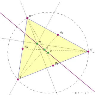
This library was designed specifically for dynamic geometric constructions on the web, where the user can manipulate almost anything and see the consequences in real-time. This approach is specially useful for demonstrations of geometric theorems, like the Euler line theorem (See Figure 2.2). In the example presented in Figure 2.2, the user is free to manipulate the points A, B and C, changing the geometry of the triangle, while the points H, S and U remain collinear, demonstrating the Euler line theorem. This capability of JSXGraph is very good to teach and explore complex geometric structures in an interactive way.
2.4. CONCLUSIONS 9
Figure 2.2: Euler line theorem represented with JSXGraph.
2.4
Conclusions
In this chapter we introduced the necessary background to understand the technologies used in this work, presenting the state of the art regarding the technologies used to im-plement the web application described in this thesis.
We started by presenting some health solutions designed to improve surgical procedures using simulators, followed by a comparison between native and web application, focusing on the strengths and weakness of both. We also introduced some aspects related to the interactive use of the web and associated technologies, namely 3D and 2D interaction. The graphics technologies described on section 2.3 are an important aspect to this thesis, since the main goal is to develop a web application containing 2D and 3D models.
Chapter 3
Breast Reduction Surgery
Simulation
This chapter describes the simulation software used in this work. The simula-tion tools described in this chapter were designed to simulate breast reducsimula-tion surgeries which is a specific type of plastic surgery. Throughout this chapter, all the components of the simulation software, as the connections between the simulation stages, are described in detail. This simulation software is also the basis of the web application described in Chapter 4.
3.1
Introduction
As mentioned in Chapter 1, the work described in this thesis is based on software that simulates breast reduction surgeries. This software was developed by some members of the VAPS project, namely the authors of the work presented in [21] and [19], which was achieved by the use of mathematical techniques related with breast modeling and simulation.
The software is made of two tools: the surgery simulator and the displacement simulator. The first one is used to simulate the surgery itself, while the second one is used to apply a gravity field to the post-surgery model.
This chapter explains how these tools work together and how they can be used to simulate breast reduction surgeries. We will also explain the relations with some auxiliary tools, such as Finite Volumes Library (FVLib) and the G mesh (Gmsh).
12 CHAPTER 3. BREAST REDUCTION SURGERY SIMULATION
3.2
Numerical Simulation Software
The simulation of breast reduction surgery is divided in three main steps: 1) the first step is dedicated to the definition of the breast geometry and the breast incision angles; 2) the second step is the surgery simulation itself; and 3) the last step is the application of the gravity field to the previous result.
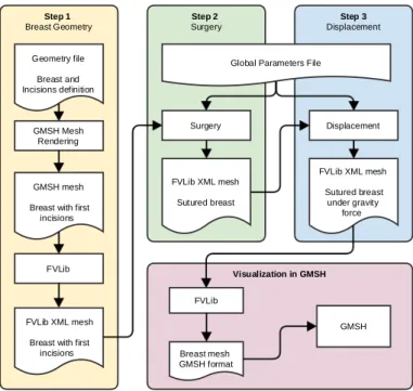
All of these steps use software simulation tools that have their own operation and are still in the development stage. These tools are the Surgery Simulator and the Displacement Simulator. The Surgery Simulator receives a previously defined breast mesh that repre-sents the patient breast and the incision parameters that will be used to make the breast reduction surgery. This initial mesh is obtained with an existent template file filled with the new parameters (Geometry file Fig. 3.1). After that the software performs the surgery simulation, suturing the incisions made on the breast mesh. The Displacement Simulator that receives the mesh produced by the Surgery Simulator and places it in a customizable gravitational field to understand the behavior of breast under gravity.
The first step is used only for the definition of the breast geometry and planning the
incisions, so there is no need of a simulation tool in this step. The workflow of the
simulation process is shown in Fig. 3.1.
Visualization in GMSH Step 3 Displacement Step 2 Surgery Step 1 Breast Geometry GMSH Mesh Rendering Geometry file Breast and Incisions definition GMSH mesh Breast with first
incisions
FVLib
FVLib XML mesh Breast with first
incisions
Surgery
Global Parameters File
FVLib XML mesh Sutured breast Displacement FVLib XML mesh Sutured breast under gravity force FVLib GMSH Breast mesh GMSH format
Figure 3.1: Overall structure of Simulation Software.
The simulation tool use a library called FVLib that provides a layer for complex mathemat-ical calculations and a XML specification for 3D models. This custom 3D representation (FVLib XML mesh) is used between all the simulation programs, and the 3D breast model must be in this format. This library also provides some tools that converts .msh (Gmsh
3.2. NUMERICAL SIMULATION SOFTWARE 13 mesh format) into FVLib XML format and vice-versa. These auxiliary tools are described in Section 3.6.
In order to make all the set of parameters accessible for all the simulation tools, there is a global parameters file made in XML (See Figure 3.1), where all the required parameters are defined. The structure of the global parameters file is defined in Section 3.2.1.
3.2.1 Global Parameters File
The global parameters file is shared between the simulation tools and is used to store the parameters of all steps, including some parameters related with the simulation algorithm, such as the maximum number of iterations. The structure of a normal parameters file is presented in Listing 3.1.
1 <?xml version="1.0" encoding="ISO-8859-1"?> 2 <FVLIB>
3 <PARAMETER>
4 <!-- Filenames definition -->
5 <parameter CirurgiaMeshFile="breast.xml"
6 CirurgiaPositionFile="position.xml"
7 CirurgiaDisplacementFile="displacement.xml" />
8 <parameter SuturedMeshFile="breast_sutured.xml"
9 SuturedPositionFile="position.xml"
10 SuturedDisplacementFile="displacement.xml" />
11
12 <!-- Surgery and Displacement simulation related parametes -->
13 <parameter Lambda="1000" Mu="150" Density="1000"
14 CoefChassignac="60000" />
15 <parameter LambdaP="8000" MuP="1600" SkinThickness="0.002" /> 16 <parameter XGravity="0.0" YGravity="0.0" ZGravity="-9.8" />
17 <parameter EpsilonDerivative="1.e-8" DerivativePrecision="1.e-10"
18 MaxIter="1000" />
19 <parameter NormEpsilon="1.e-6" LogParameter="1.e-8" /> 20
21 <!-- Parameters related with the breast modeling -->
22 <parameter TransformLeft="15" TransformRight="15" TransformBotL="0" 23 TransformBotR="0" Plano_Rot="0" />
24 <parameter H="0.14" R="0.10" S="0.06" /> 25
26 <!-- Simulation specific parameters -->
27 <parameter ZMinFixation="-1.0" ZMaxFixation="-0.03"
28 RotationFixation="0.0" />
29 <parameter CodeFixation="1" CodeChassignac="2" CodeSkin="3" />
30 <parameter CodeLeftSuturation="4" CodeRightSuturation="5"
31 CodeBottomSuturation="6" />
32 <parameter CodeDoubleSuturationLeftSide="7"
14 CHAPTER 3. BREAST REDUCTION SURGERY SIMULATION
34 CodeTableMatchRight="10" CodeJoin="11" />
35 <parameter CodeDispLeft="104" CodeDispRight="105" />
36 </PARAMETER>
37 </FVLIB>
Listing 3.1: Global Parameters File
The parameters file starts with a typical XML header where the version and encoding are defined (Line 1). After that, there is a XML block delimited by the tags <FVLIB> and <PARAMETER> (Lines 2, 3, 36 and 37), which is a container for all the defined parameters. The first set of parameters are related with the filenames that will be used during all the simulation process (Lines 5 to 10):
• The CirurgiaMeshFile is the input file that contains the breast model with the
breast geometry and incisions definition. The CirurgiaPositionFile and the
CirurgiaDisplacementFile are auxiliary files that must be generated during the simulation and do not contain anything that can be visualized.
• The SuturedMeshFile is the output model of the surgery simulation, that after the displacement process takes place, will generate the SuturedPositionFile, which is an auxiliary file and the SuturedDisplacementFile, which is the displacement that must be applied to surgery result (SuturedMeshFile) in order to simulate the given gravity on the breast model.
The next set of parameters are related with the simulation itself (Lines 13 to 19). The Lambda, Mu, Density, CoefChassignac, LambdaP, MuP and SkinThickness are related with the Surgery process, while XGravity, YGravity and ZGravity are the parameters for the Displacement process. The EpsilonDerivative, DerivativePrecision, MaxIter, NormEpsilon and LogParameter are used to finely tune the simulation algorithm. The third set of parameters are related with breast modeling and the incisions definition (Lines 21 to 24). The TransformLeft, TransformRight, TransformBotL, TransformBotR and Plano Rot are related to the incisions angles and to the suture plane, while H, R and S are related with the breast geometry. The last parameters must be included in the global parameters file because they are needed across all the simulation steps.
The last set of parameters are related with the creation of the 3D model (Lines 26 to 35), namely the codes assigned to the faces in order to distinguish the different parts of the breast.
3.3. BREAST PARAMETRIZATION 15
3.3
Breast Parametrization
In the first step of the surgery simulation process, the surgeon will input all pre-surgery aspects related to the patient physiognomy. This step is divided in two parts: 1) the definition of the breast geometry and 2) the incisions parameters.
The definition of the breast geometry is made by a sectioned sphere and the surgeon only needs to input two parameters: the depth of the breast (H), which represents the place where the sphere is sectioned by a vertical plane, and the radius of the circle (R) made by the intersection between the vertical plane and the sphere that represents the breast radius close to the chest.
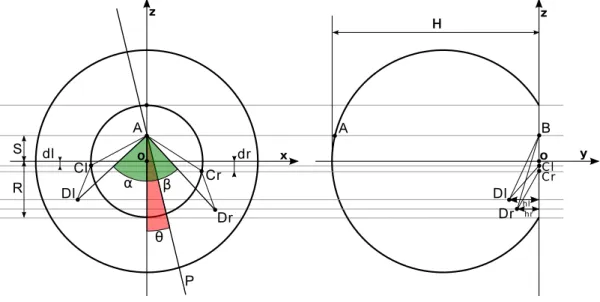
Figure 3.2 represents the initial breast geometry with all the measurements needed by surgeon to define the geometry of the breast and the incisions that will be made.
A O S R Cr Dr A H z y x B Cr O Dr z β α Dl Cl dr dl Dl Cl θ hl hr P
Figure 3.2: Breast Geometry
To model the surgery, the surgeon must define four incisions: two in the front of the breast (left and right side) and two in the rear of the breast, close to the chest. The frontal incisions are made with two planes orthogonal to the chest through point A, which is the new position of the nipple. The left and right incisions form an angle of α and β degrees, respectively, with the z negative axis. The new position of the nipple can be modified by changing the value of S. The rear incisions are made with two obliques planes to the chest. In the right side of the breast the plane goes through B, Cr and Dr with a distance hr between Dr and z axis. The left plane passes through B, Cl and Dl with a distance hl between Dl and the z axis. In order to finely adjust this planes, the surgeon can change the values of dl and dr, which will affect Cl and Cr. He can also modify s, which will change the position of points A and B. The surgeon is also free to manipulate the plane P , which defines the angle of the suture. If the angle is zero, the suture will be
16 CHAPTER 3. BREAST REDUCTION SURGERY SIMULATION symmetric, but if is greater or lesser than zero the suture will be made in the right or left side, respectively.
This is the most important step in the entire surgery simulation since this is the step where all the patient customization is made. An error in this initial parametrization will lead to an unrealistic surgery simulation that will not correspond to the results of a real surgery. The simulation software cannot check if the entered parameters make sense from a surgical point of view.
3.3.1 Components
The initial parametrization with the parameters presented in the last section is made with an external tool called Gmsh that is a “3D finite element mesh generator with built-in pre- and post-processing facilities” [27]. Gmsh has it’s own scripting language to define
3D meshes, which is used to parametrize the initial breast model. The result of the
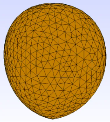
parametrization script is shown in Fig. 3.3a (only with geometry rendering) and in Fig. 3.3b (with 3D mesh rendering). Figure 3.3a is the viewable result before the step “Gmsh mesh rendering” step presented in Fig. 3.1, while Fig. 3.3b is the result after this first step. The 3D mesh presented in Fig. 3.3b considers all parameterization done by the surgeons. If the surgeon is satisfied, he can continue to the next phase, the surgery simulation. If there is something to adjust, the Gmsh script has to be modified in order to reflect these new adjustments and the 3D mesh needs to be rendered again.
(a) Gmsh geometry rendering (b) Gmsh 3D mesh rendering
Figure 3.3: Gmsh rendering
3.4
Surgery Simulation
After the definition of the parameters related to the breast geometry and incisions, we are ready to advance to the next step, the surgery simulation. In this step, the incisions defined in the previous step will be sutured according to the parameters introduced by the surgeon.
3.5. DISPLACEMENT PROCESS 17 The breast surgery is a very complex process, so even small adjustments in the parameters can have a large impact in the final shape of the breast, which is very important for the patient comfort after the surgery. The surgery parameters are related with the dynamics of the breast, such as the Breast Density, Skin Thickness, Elasticity and Compressibil-ity of the skin and the interior tissue, and the Chassignac Coefficient which affects the interaction of the breast with chest [21].
To perform the surgery simulation, the mesh produced in the parametrization step must be converted to the FVLib XML format, making it compatible with the surgery simulation tool. This conversion is made with fvcm, a tool included in the FVLib library. After that the global parameters file (See Section 3.2.1) must be created, including all the parameters related to the surgery simulation process, namely the parameters defined in the first step that are related to the breast geometry and to the incisions, the parameters introduced in this step related to the breast dynamics, and the parameters that will be defined in the next step, which are not available in this step. This parameters file also contain the location of all files needed for the simulation, including the input and output filename of the surgery simulation and the displacement simulation together with some other auxiliary files that are needed. The parameters file is not created before because the simulator is only executed from the surgery simulation. After the parameters file is correctly configured and the input mesh calculated, the surgery simulator is ready to be executed.
Fig. 3.4 presents the result of a surgery simulation in a gravity free environment. The result of the simulation is in FVLib XML format, which has to be converted into Gmsh, so that the surgeon can see the result (See Fig. 3.1).
Figure 3.4: Gmsh rendering of the breast after the surgery
3.5
Displacement Process
After the surgery simulation the surgeon has a global idea about the shape of the breast and the implications of a specific parametrization. However the breast shape obtained after the surgery simulation is not consistent with the reality due the fact that the model is in a zero gravity field. The zero gravity field is very useful when the surgeon is modeling
18 CHAPTER 3. BREAST REDUCTION SURGERY SIMULATION and parameterizing the breast, but for a realistic final evaluation, the breast model must be inserted in a gravity field.
The Displacement Process is the final stage of the simulation. In this step, the surgeon can analyze the behavior of the breast model under a defined gravity field, which means that the surgeon is free to simulate the breast behavior in all positions, even experience with gravity forces different from the ones found in Earth.
In terms of the organization of the software, this step receives the breast model created in the second stage (Surgery Simulation) alongside with a gravity vector which indicates the gravity force for each axis. The gravity vector is defined in the global parameters file like in the previous step. After that, the Displacement Process can be executed. This process generates a set of displacement vectors that represents the displacement of the breast under the specified gravity. Then, the displacement vectors are applied to the breast model calculated in the second step using fvcd, which is a FVLib tool to add a certain displacement to a gravity free model. The fvcd tool returns a new 3D breast model under the specified gravity in the FVLib XML format. This file needs to be converted into the Gmsh format so that the surgeon can visualize the result (See Fig. 3.1). An example result of the Displacement Process is shown in Fig. 3.5.
Figure 3.5: Gmsh rendering of the breast after the Displacement Process
3.6
Auxiliary Tools
As mentioned before, there are some auxiliary tools that are used in the simulation pro-cess. These tools are: 1) the FVLib library, which is used by the simulation programs to represent 3D meshes and perform some calculations, and 2) Gmsh, which is a mesh modeling tool used to build the initial breast model at the first step of the simulation. Each one of these tools has it’s own format for representing 3D meshes, but during the simulation work-flow there is the need to make a conversion between them. This
conver-3.6. AUXILIARY TOOLS 19 sion is made with tools provided by the FVLib library. Sections 3.6.1 and 3.6.2 explains the 3D representation used by Gmsh and FVLib, respectively.
3.6.1 Gmsh File Format
Gmsh has two different types of files: the geometry script file which is based on a scripting language, used to define geometry shapes and perform calculations with these shapes, and the Gmsh mesh format, which is the output format after rendering a geometry script.
Geometry File Format
The geometry file is the source-code of a 3D model before the 3D rendering. The whole structure of the 3D model must be defined in the geometry file, i.e important points, vertices, edges and polygons.
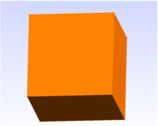
The Gmsh script language has a simple syntax, based on an incremental construction of the model. As it can be seen in Listing 3.2, which represents a cube, the script begins with the definition of all points (Lines 2 to 9) followed by the definition of the edges (Lines 12 to 2) and then the definition of the faces (Lines 26 to 31) and surfaces (Lines 34 to 39). Figure 3.6 shows a cube generated by the source-code presented on Listing 3.2 after the Gmsh rendering. Building a breast geometry is much more complex than building a simple cube, as it can be seen in the geometry template present on Annex A.
1 // Vertices Definition 2 Point(1) = {0, 0, 0}; 3 Point(2) = {.1, 0, 0}; 4 Point(3) = {0, .1, 0}; 5 Point(4) = {.1, .1, 0}; 6 Point(5) = {0, 0, .1}; 7 Point(6) = {.1, 0, .1}; 8 Point(7) = {0, .1, .1}; 9 Point(8) = {.1, .1, .1}; 10 11 // Edges Definition 12 Line(1) = {1,2}; 13 Line(2) = {2,4}; 14 Line(3) = {4,3}; 15 Line(4) = {3,1}; 16 Line(5) = {5,6}; 17 Line(6) = {6,8}; 18 Line(7) = {8,7}; 19 Line(8) = {7,5}; 20 Line(9) = {5,1}; 21 Line(10) = {6,2}; 22 Line(11) = {8,4};
20 CHAPTER 3. BREAST REDUCTION SURGERY SIMULATION 23 Line(12) = {7,3}; 24 25 // Faces Definition 26 Line Loop(13) = {1,2,3,4}; 27 Line Loop(14) = {5,6,7,8}; 28 Line Loop(15) = {-1,-9,5,10}; 29 Line Loop(16) = {-2,-10,6,11}; 30 Line Loop(17) = {-3,-11,7,12}; 31 Line Loop(18) = {-4,-12,8,9}; 32 33 // Surfaces Definition 34 Plane Surface(19) = {13}; 35 Plane Surface(20) = {14}; 36 Plane Surface(21) = {15}; 37 Plane Surface(22) = {16}; 38 Plane Surface(23) = {17}; 39 Plane Surface(24) = {18};
Listing 3.2: Gmsh geometry file representing a Cube.
Figure 3.6: Simple Cube made with Gmsh
The first code block (Lines 2 to 9) of the Gmsh geometry file (Listing 3.2) is the definition of the cube vertices i.e. the declaration of the coordinates that form the cube. Each point is made of two components: a number that identifies the point(L) and a set of coordinates (X, Y and Z), according to Listing 3.3.
1 Point(L) = {X, Y , Z};
Listing 3.3: Point syntax.
The second code block (Lines 12 to 2) is the definition of the edges that make the cube. Each edge (Line) is made of three components: a number that identifies the edge (L), a
number that references the first vertice of the edge (V1) and a number that references the
3.6. AUXILIARY TOOLS 21
1 Line(L) = {V1, V2};
Listing 3.4: Line syntax.
The third code block (Lines 26 to 31) is the definition of the cube faces. Each cube face (Line Loop) is made of two components: a number that identifies the face (L) and a list
of edges that compose the face (E1, E2, E3 and E4), which in the case of the cube are
four edges. The minus signal behind the edge number means that edge are interpreted reversely i.e: if a edge was previous defined from point A to point B, with the minus signal it is interpreted from point B to point A. Listing 3.5 presents the syntax of the Line Loop element.
1 Line Loop(L) = {E1, E2, E3, E4};
Listing 3.5: Line Loop syntax.
The last code block (Lines 34 to 39) is the definition of a surface. The main differences from the Line Loop element are: the Plane Surface element may reference more than one Line Loop, while the Line Loop can only build a face (with more than three edges). Regarding the 3D rendering, only the Plane Surface will generate the opacity of the cube faces, otherwise it will be generated a wireframe cube. The main advantage of the Plane Surface is the possibility to create a new surface composed by n previously defined holes (Line Loop). In the case of the cube, each node of a Plane Surface is made of two components: a number that identifies the surface (L) and a number that references the face of the cube
(Line Loop) (F1), as shown in Listing 3.6.
1 Plane Surface(L) = {F1};
Listing 3.6: Plane Surface syntax.
The syntax described in the last paragraphs is based on the Gmsh Reference Manual [28].
Mesh File Format
The Gmsh mesh format is very extensive [28], in this section we only describe the elements used by the simulation process and supported by FVLib converters. The example source-code presented in Listing 3.7 represents a simple cube.
The mesh format is composed by three main blocks (Listing 3.7): 1) the indication of the mesh format version, which is delimited with $MeshFormat (Line 1) and $EndMeshFormat tags (Line 3); 2) the definition of all the points (nodes) that form the mesh, which are defined between the $Nodes (Line 4) and $EndNodes tags (Line 14); and 3) the definition of the geometric primitives built with the nodes defined before delimited with the $Elements (Line 15) and $EndElements tags (Line 23).
22 CHAPTER 3. BREAST REDUCTION SURGERY SIMULATION Each line of the nodes definition block (Lines 4 to 14) is made by the node number, which is the label of the node, and the three coordinates of the point. The first line of the block is an exception, reserved to define the number of nodes that form the mesh.
In the elements definition block (Lines 15 to 23), each line is composed by: the element number, which is the label of the element; the element type which is the type of the geometric primitive that we want (1 for lines, 2 for triangles, 3 for quadrangles, 4 for tetrahedrons and so on); the numbers of the element tags that comes next; the element tags (not used by the simulation process) and finally the node list that compose the geometric element, defined with the node numbers declared in the previous block (Lines 4 to 14). As in the previous block, the first line indicates the number of elements defined in the current block.
1 $MeshFormat 2 2.2 0 8 3 $EndMeshFormat 4 $Nodes 5 8 6 1 0.0000 0.0000 0.0000 7 2 0.0000 1.0000 0.0000 8 3 0.0000 1.0000 1.0000 9 4 0.0000 0.0000 1.0000 10 5 1.0000 0.0000 0.0000 11 6 1.0000 1.0000 0.0000 12 7 1.0000 1.0000 1.0000 13 8 1.0000 0.0000 1.0000 14 $EndNodes 15 $Elements 16 6 17 1 3 0 1 2 3 4 18 2 3 0 5 6 7 8 19 3 3 0 6 2 3 7 20 4 3 0 5 1 4 8 21 5 3 0 8 7 3 4 22 6 3 0 6 2 1 5 23 $EndElements
Listing 3.7: Gmsh file format
3.6.2 FVLib XML File Format
The FVLib file format uses XML to define the 3D model and is divided in four parts: 1) the list of all points and respective coordinates of the 3D model; 2) the list of the edges of the 3D model, i.e. the definition of connections between two or more collinear points; 3) the list of the faces made by three or more edges; 4) the list of the cells composed by
3.6. AUXILIARY TOOLS 23 one or more faces. These four different kinds of definitions are modeled as four different XML blocks, as seen in Listing 3.8.
1 <?xml version="1.0" encoding="ISO-8859-1"?> 2 <FVLIB>
3 <MESH dim="3" name="3Dmesh"> 4 <VERTEX nbvertex="4">
5 <!-- label code coordinates -->
6 1 1 0.0000 0.0000 0.0000 7 2 1 0.0000 1.0000 0.0000 8 3 1 0.0000 1.0000 1.0000 9 4 1 0.0000 0.0000 1.0000 10 </VERTEX> 11 <EDGE nbedge="4">
12 <!-- label code numberOfVertices listOfVertices -->
13 1 0 2 1 2 14 2 0 2 2 3 15 3 0 2 3 4 16 4 0 2 4 1 17 </EDGE> 18 <FACE nbface="1">
19 <!-- label code numberOfEdge listOfEdges -->
20 1 0 4 1 2 3 4
21 </FACE>
22 <CELL nbcell="1">
23 <!-- label code numberOfFaces listOfFaces -->
24 1 0 1 1
25 </CELL>
26 </MESH> 27 </FVLIB>
Listing 3.8: FVLIB XML file format
The FVLib file format begins with the typical tag found on XML documents, where the XML version and the encoding are defined. After that, there is a block called FVLib (Lines 2 to 27) which is a container for all the model data. Inside de FVLib block there is another block called MESH (Lines 3 to 26) which indicates that we are defining a Mesh in three dimensions (dim field), called “3Dmesh” (name field).
The next block is the VERTEX definition (Lines 4 to 10) which is a container for all the vertices that form the mesh. The field nbvertex indicates the number of vertices defined inside the block.
Each line of the VERTEX block (Lines 6 to 9) is made by three components: a label that identifies the vertex, a code that can be used to distinguish different kinds of vertices and a list of coordinates.
Then is defined the EDGE block (Lines 11 to 17) which is a container for the edges that form the mesh. The field nbedge indicates de number of edges defined.
24 CHAPTER 3. BREAST REDUCTION SURGERY SIMULATION Each line of the EDGE block (Lines 13 to 16) is composed by four parts: a label that identifies the edge, a code that can be used to distinguish different kinds of edges, the number of vertices that made the edge and a list of vertices labels referencing the vertices defined in the last block.
Follows the FACE block (Lines 18 to 21) which contains all the faces that compose the mesh. The field nbface indicates the number of faces defined.
Each line of the FACE block (Line 20) is made by four components: a label that identifies the face, a code that can be used to distinguish different kinds of faces, the number of edges that form the face and a list of edges labels referencing the edges defined in the EDGE block.
The last block is the CELL block (Lines 22 to 25), which contains the faces that form a cell. The field nbcell indicates the number of cells defined.
Each line of the CELL block (Line 24) is made by four parts: a label that identifies the face, a code that can be used to distinguish different kinds of faces, the number of faces that forms the cell and a list of faces labels referencing the faces defined in the last block.
3.7
Conclusions
In this chapter was described the simulation software that is the basis of the web applica-tion made in this work. The comprehension of the simulaapplica-tion software workflow and its auxiliary tools is fundamental to create the abstract layer described in Chapter 4 necessary to the proper functioning of the web application.
Throughout this chapter was described in detail all the simulation steps needed to com-plete a surgical simulation, from the geometry file until the displacement calculus, passing through the 3D representation using Gmsh and FVLib formats.
Chapter 4
Web Application for Breast
Reduction Simulation
This chapter presents the Web Application for Breast Reduction Simulation implemented in the context of this work, including it’s architecture and the necessary improvements to the Simulation Software in order to make it com-patible with a web based application. This chapter also details each step of the simulation process using the web application.
4.1
Introduction
Breast reduction surgery is a complex process, where small changes can have a huge impact in the final breast shape, and when not done in the right way, it can lead to catastrophic results which are hard to solve. In order to achieve a realistic surgery simulation, surgeons must be able to manipulate and interact with the breast model in all steps of the simulation process: 1) Breast parametrization; 2) Surgery simulation and 3) Gravity simulation. To allow an easy interaction with the simulation process, including an adequate breast modeling, it was decided to create a web application that reflects the simulation process in an easy way. This web application should use recent 3D capabilities found on modern web browsers to give the surgeon the freedom to inspect and interact with the 3D breast model before and after the simulation of the surgery. It was also decided that the interface should be as intuitive as possible and avoid the use of any type of client-side plugins. This aspects are very important because they eliminate the majority of barriers between
26 CHAPTER 4. WEB APPLICATION FOR BREAST REDUCTION SIMULATION surgeons and this simulation tool, since the web application is virtually accessible from any device with a modern browser and an internet connection.
To implement the web application it was decided to use X3DOM [16], which is an open-source JavaScript framework and runtime for 3D graphics on the web, based on WebGL [16]. Using X3DOM it is possible to create 3D scenes inside an HTML5 web page, allowing to visualize and interact with these 3D graphics on HTML5-enabled browsers without the need of any client-side plugins.
Although X3DOM is not part of the HTML5 specification, it’s the best candidate to fulfill the current HTML5 specification for declarative 3D content [16].
4.1.1 Web Application Architecture
The web application is made of three layers: • User Interface
Responsible to present the content to the final user and catch the user actions. • Process the UI content
Process the user requests, delegates the hard work to the execution layer and wait for the results. This layer is implemented in PHP.
• Execution
Responsible for the execution of user requests and sending the results back. This layer is implemented in Python.
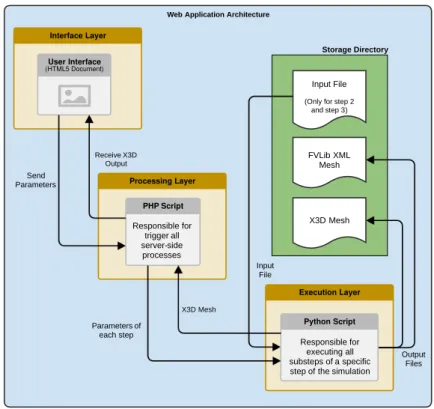
The layers are interconnected as described in the diagram presented in Figure 4.1. The normal work-flow of the web application starts with some parametrization made by the user on the interface. Then these parameters are sent to the Processing layer, which in turn will trigger the Execution with the user parameters. The Execution layer executes the simulation for the actual simulation step and saves the results inside a storage area. Note that each simulation step (Breast Parametrization, Surgery and Gravity Application) has it’s own implementation of each described layer, each one specialized on a specific simulation step.
After the Execution layer has finished, the results are sent to the Processing layer, which in turn will send them to the User Interface.
The Execution layer only receives an input file on the second and third step because these steps need the previous result to continue, i.e. the surgery simulation step needs the parametrization made in the first step, and the Gravity Application step needs the Surgery simulation result to apply the gravity. The first step doesn’t have dependencies, so there is no need to input any file into the Execution layer.
4.1. INTRODUCTION 27
Web Application Architecture
FVLib XML Mesh
X3D Mesh Input File
(Only for step 2 and step 3) Storage Directory Parameters of each step Input File Output Files X3D Mesh Interface Layer User Interface (HTML5 Document) Receive X3D Output Send
Parameters Processing Layer PHP Script Responsible for trigger all server-side processes Execution Layer Python Script Responsible for executing all substeps of a specific step of the simulation
Figure 4.1: Web Application Architecture
Cache Feature
In the Processing layer it was added a feature that checks the user request/parametrization, and if there is an already calculated mesh with the same set of parameters, that file is directly presented to the user, without the need to recalculate it. This feature acts like a cache, allowing the user to switch between the simulation steps without loosing time calculating what it’s already been calculated.
When the cache system is triggered, the Execution layer is not reached, because the result is directly obtained by the Processing layer.
The cache system is only activated if the previous parameters were equal to the actual parameters. If this is true, it means that the previous calculated result is the same as the correct result. Due to this, the recalculation time is saved, and the last result is immediately presented. This can vary between seconds to minutes depends on the selected mesh quality.
4.1.2 Web Application Development
The development of the web application was made in several stages. In a first step it was made a Gmsh to X3D format converter. This is necessary to present a 3D model of the breast in the web browser, and Gmsh is not suitable for that task.
28 CHAPTER 4. WEB APPLICATION FOR BREAST REDUCTION SIMULATION Then, it was made the first prototype, consisting of a web page that was made with HTML forms with all possible parameters of the simulation, an upload area where the user should upload the initial parametrization of the breast using the Gmsh geometry file format and a frame in a corner of the page that shows the result of the simulation.
After receiving some feedback of the team that was developing the simulation software, we concluded that this design/architecture was good enough for a first approach, but not enough to be used by surgeons.
The initial parametrization was still made through the scripting language provided by Gmsh and during the simulation process, users could not make any changes or visualize the intermediate steps until the simulation end. The solution was to split the simulation process in three main steps: the initial parametrization and modeling of the breast; the surgery itself; and the displacement step. Each one of this steps have it’s own parameters and 3D model of the breast. To achieve this design we automated all the steps using a Python script. Also, in the first step, the application generates the Gmsh script that was necessary to upload in the previous version, based on a few parameters that describe the breast geometry and the incisions that will be made during the surgery. Note that all calculations are performed on server-side. At this point the web application was divided into three pages, representing the three steps of the simulation. According to all project members, this version was much better than the previous one and theoretically, it could be used by anyone that have medical knowledge.
The development process was made in parallel with the development of the simulation software, introducing incremental updates which should be included in the web application. With these updates, it was suggested to introduce an alternative method of inputting the breast parameters in the first step, namely a visual method where the surgeon can understand the relation between all parameters and the impact of changing any of them. After this suggestion, we started to build the interactive diagram that is present on the actual version of the web application (Fig. 4.8). To do so, we used a JavaScript library, called JSXGraph that creates a very intuitive layer to build interactive geometric shapes in web pages. The development of this 2D diagram was a complex task, since the ge-ometry related with the 2D representation of the breast must be accurate, otherwise the parameters will be inconsistent.To do so, we introduced the mathematical formulas that define the breast model into the logic of the 2D diagram.
After we made a stable version of the web application with the diagram we received some good reviews about the application, including reviews from a doctor and a physician, part of the project team, which appreciated the work made on the web application.
4.2. AUTOMATING THE SIMULATION PROCESS 29
4.2
Automating the Simulation Process
The surgery simulation process described in the Chapter 3 has a complex work-flow, so we needed to simplify the overall structure of the simulation in order to make it compatible with a web application.
The first thing to do is to group the activities related with each step of the simulation, into one single tool that receives as input all the parameters related with each step of the simulation. Figure 3.1(page 12) shows the grouping of the various steps of the simulation. To address this problem, it was decided to build a Python [41] application that will hide all the subtasks needed by each step. Each simulation step will be associated with a Python application that abstracts all the subtasks needed by the step. The choice of Python is related to the fact that this is a very powerful tool in several domains, from scientific computation to simple scripting tasks. Due the simplicity of the Python syntax, the automation of the several steps becomes more simple to implement
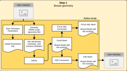
First Step - Breast Parametrization
The first step is about the definition of the initial model of the breast and it’s parametriza-tion. As represented in Fig. 3.1, the generation process of the breast mesh from the initial geometry file, and it’s conversion to the FVLib XML format must be automated. The parameters file must be defined with the parameters in this step. To do so, was created a Python application that receives as input the following parameters (as described in Fig. 3.2):
• Radius of the breast (R distance) • Depth of the breast (H distance)
• Angles of frontal incisions (α and β angles) • Angle of suture (θ angle)
• Distance between chest and the bottom incisions (hl and hr distances) • The new position of the nipple (S distance)
• Adjustments on the incision planes (points dl and dr) • Mesh Quality
The first task to be done is the creation of the Gmsh geometry file with these parameters. This is made with a template file that is modified by the Python application (See Annex A for detailed information about this template). In this template the following variables are updated:
30 CHAPTER 4. WEB APPLICATION FOR BREAST REDUCTION SIMULATION • R, which is the Breast Radius in meters
• H, which is the Breast Depth in meters
• a lef t, which is the Left Incision Angle in radians • a right, which is the Right Incision Angle in radians
• s, which correspond to the s distance in Figure 3.2(page 15) • dl, which is the dl distance in Figure 3.2
• dr, which is the dr distance in Figure 3.2
• h2l, which is the distance of the Bottom Left Incision with a shift • h2r, which is the distance of the Bottom Right Incision with a shift
• lc, which is the Mesh Quality Coefficient (0.15 - Thin; 0.2 - Normal; 0.3 - Coarse). Scaled with the Breast Radius. Directly influences the distance between vertices.
After that, the Python application will generate the geometry file using Gmsh, and convert the resulting mesh into the FVLib XML format and X3D, both a representation of the defined breast model. The FVLib XML file must be generated because the next step of the simulation will need this file to proceed, but in order to show the result of this step in the browser it must also be converted to X3D. The X3D conversion process is explained with detail in Section 4.2.1.
This first process also updates some parameters in the global parameters file used in the surgery simulation. The work-flow of the first step can be visualized in Figure 4.2.
Optional: Visualization in Gmsh Step 3 Displacement Step 2 Surgery Step 1 Breast geometry Gmsh geometry file breast and incision
definition
Gmsh mesh breast with first
incisions
FVLib
FVLib XML mesh breast with first
incisions surgery surgery parameters FVLib XML mesh sutured breast displacement gravity parameters FVLib XML mesh sutured breast under gravity force FVLib Gmsh Breast mesh Gmsh format Step 1 Breast geometry Step 2 Surgery User interface User interface User interface User interface Step 3 Displacement User interface User interface GMSH File with Breast Geometry and Incisions Definition
Gmsh Mesh Breast Model with
the Incisions FVLib XML Conversion
FVLib XML Mesh Breast Model with the Incisions
X3D Conversion
X3D Mesh Breast Model with
the Incisions Generate GMSH script (geometry file) Python Script Python Script Surgery Global Parameters File FVLib XML Mesh Breast Sutured Save Surgery Parameters X3D Conversion X3D Mesh Breast Sutured Python Script Displacement Global Parameters File FVLib XML Displacement File Save Displacement Parameters FVLib Conversion to GMSH X3D Mesh Sutured Breast under Gravity FVLib XML Mesh Breast Sutured GMSH Mesh Sutured Breast under Gravity X3D Conversion Save Geometry Parameters Global Parameters File FVLib XML Mesh (Step 1) FVLib XML Mesh (Step 2)
4.2. AUTOMATING THE SIMULATION PROCESS 31
Second Step - Surgery Simulation
The second step is about the surgery simulation itself and the parametrization of some aspects related with the breast dynamics. So, the Python application for this step will receive as input the file generated in the last step alongside the following parameters:
• Lambda and Mu, which are two coefficients that define the breast as an elastic material.
• Breast Density, which is the density of the breast, i.e. weight divided by volume.
• Chassignac Coefficient, which is the coefficient that defines the connection between the breast and chest, as a spring.
• LambdaP and MuP, which defines the elasticity of the breast skin.
• Skin Thickness, which is the thickness of the breast skin.
With these inputs, the Python program will add the new parameters to the global param-eters file and execute the surgery simulation program.
The surgery simulation process returns a FVLib XML file with the breast model after the suture. After that the FVLib XML file is converted into X3D in order to be visualized in a web browser. The surgery process can be seen in Figure 4.3. The X3D conversion process is explained with detail in Section 4.2.1.
Optional: Visualization in Gmsh Step 3 Displacement Step 2 Surgery Step 1 Breast geometry Gmsh geometry file breast and incision
definition
Gmsh mesh breast with first
incisions
FVLib
FVLib XML mesh breast with first
incisions surgery surgery parameters FVLib XML mesh sutured breast displacement gravity parameters FVLib XML mesh sutured breast under gravity force FVLib Gmsh Breast mesh Gmsh format Step 1 Breast geometry Step 2 Surgery User interface User interface User interface User interface Step 3 Displacement User interface User interface GMSH File with Breast Geometry and Incisions Definition
Gmsh Mesh Breast Model with
the Incisions FVLib XML Conversion
FVLib XML Mesh Breast Model with the Incisions
X3D Conversion
X3D Mesh Breast Model with
the Incisions Generate GMSH script (geometry file) Python Script Python Script Surgery Global Parameters File FVLib XML Mesh Breast Sutured Save Surgery Parameters X3D Conversion X3D Mesh Breast Sutured Python Script Displacement Global Parameters File FVLib XML Displacement File Save Displacement Parameters FVLib Conversion to GMSH X3D Mesh Sutured Breast under Gravity FVLib XML Mesh Breast Sutured GMSH Mesh Sutured Breast under Gravity X3D Conversion Save Geometry Parameters Global Parameters File FVLib XML Mesh (Step 1) FVLib XML Mesh (Step 2)
32 CHAPTER 4. WEB APPLICATION FOR BREAST REDUCTION SIMULATION
Third Step - Application of Gravity
The last step is the application of a gravity field to the breast model, also called the dis-placement process due to the disdis-placement that the breast will suffer, in order to simulate the gravity. This step is very similar to the previous one, also having a Python script that processes all the parameters.
The application receives as input the result of the previous step, which is the breast model after the suture, along with the parameters of this step, which in this case is a vector that represents the gravitational field that will be applied. The application will add the new parameters to the global parameters file and execute the displacement simulation software. This software will calculate the amount of displacement for each breast cell according to the given gravity field, returning a special FVLib file that represents the final displace-ment. After that, the displacement must be applied to the previous step. This merge is made with the help of FVLib, which has a tool specifically made for this task. The result of the converter is a Gmsh mesh that must be converted to X3D in order to be viewable in a web browser. The X3D conversion process is explained with detail in Subsection 4.2.1. All the stated workflow is shown in Fig. 4.4.
Optional: Visualization in Gmsh Step 3 Displacement Step 2 Surgery Step 1 Breast geometry Gmsh geometry file breast and incision
definition
Gmsh mesh breast with first
incisions
FVLib
FVLib XML mesh breast with first
incisions surgery surgery parameters FVLib XML mesh sutured breast displacement gravity parameters FVLib XML mesh sutured breast under gravity force FVLib Gmsh Breast mesh Gmsh format Step 1 Breast geometry Step 2 Surgery User interface User interface User interface User interface Step 3 Displacement User interface User interface GMSH File with Breast Geometry and Incisions Definition
Gmsh Mesh Breast Model with
the Incisions FVLib XML Conversion
FVLib XML Mesh Breast Model with the Incisions
X3D Conversion
X3D Mesh Breast Model with
the Incisions Generate GMSH script (geometry file) Python Script Python Script Surgery Global Parameters File FVLib XML Mesh Breast Sutured Save Surgery Parameters X3D Conversion X3D Mesh Breast Sutured Python Script Displacement Global Parameters File FVLib XML Displacement File Save Displacement Parameters FVLib Conversion to GMSH X3D Mesh Sutured Breast under Gravity FVLib XML Mesh Breast Sutured GMSH Mesh Sutured Breast under Gravity X3D Conversion Save Geometry Parameters Global Parameters File FVLib XML Mesh (Step 1) FVLib XML Mesh (Step 2)
Figure 4.4: Architecture of the third step.
4.2.1 X3D Converters
As mentioned in Section 3.6, the simulation software relies on two file formats to represent the 3D models. These formats are the Gmsh and the FVLib XML file formats, detailed
![Figure 2.1: Graphic technologies in HTML5. Retrieved from [16].](https://thumb-eu.123doks.com/thumbv2/123dok_br/19289036.990834/28.892.254.637.172.412/figure-graphic-technologies-html-retrieved.webp)