Abstract—There is no doubt that today manufacturing is more competitive and challenging than ever before in trying to respond to “production on demand”. Companies from east and west and all over the world have changing rules of business and need to collaborate beyond geographic boundaries with the support of the rapid advancement of information technology associated with manufacturing technology. This paper describes and illustrates a STEP compliant CAD/CAPP/CAM System for the manufacture of rotational parts on CNC turning centers. The information models to support the proposed system together with the data models defined in the ISO14649 standard used to create the NC programs are also described. A structured view of a STEP compliant CAD/CAPP/CAM system framework supporting the next generation of intelligent CNC controllers for turn/mill component manufacture is provided. Finally the authors proposed system is outlined by the modeling of a turn/mill workstation and through the use of user interface dialogs that depict the information held in the models. A case study component has been developed to prove the concept for using the milling and turning parts of ISO14649 to provide a turn-mill CAD/CAPP/CAM environment.
Index Terms—CAD/CAPP/CAM, CNC, ISO 14649, STEP-NC.
I. INTRODUCTION
Today, with the use of computer technologies and communication technologies in the manufacturing industries, the methods mentioned above are largely being replaced by Computer Aided Design (CAD) and Computer Aided Manufacturing (CAM) to implement concurrent engineering.
Widespread CADCAM systems will reduce human
interaction and the result, should be increased production, reduced costs and better quality of product. Manufacturing companies invariably have more than one CNC machine model due to business development, technology and market demand. CNC machines now, utilize a variety of cutting technologies such as multi turrets and multi spindles in complex axial configurations increasing the level of flexibility compared to the machines of the previous decade[1]. A large number of CAx systems have been developed and implemented in recent years to support all stages of product life by computer systems and many can simulate a virtual CNC machining with the complete machine toolpath [2].
Manuscript received July 22, 2008. This work was supported in part by the Malaysia Government of UTHM Short Grant 0 532
Yusri Yusof is with the University of Tun Hussein Onn Malaysia (UTHM), 86400 Parit Raja, Johor, Malaysia. phone: 607-4537982; fax: 607 -453 6080; e-mail: [email protected].
Keith Case was with Loughborough University, Loughborough, Leicestershire, LE11 3TU, United Kingdom.
Most of these systems are specialized to support certain applications, and are based on an information model that handles the application specific view of the product. These CAx systems do not share common databases for the product information. Since the first NC machine was introduced in 1947, various processes planning packages have been developed and each system tried to interpret the part data format more reliably. To date there are more than 2000 CNC models around the globe, and turning centers need a single standard particularly in the area of machining to improve productivity by increasing the richness of interactions and transactions. An initial standard is ISO 10303, informally known as the STandard for the Exchange of Product (STEP) Data which aims to provide a single International Standard for all aspects of technical product [3]. This paper presents an overall review of the various research projects carried out by the major research groups. The relevant research issues for the development and introduction of reconfigurable machines tools are presented focused on turning operations. Finally, the authors propose a STEP-NC compliant CAD/CAPP/CAM system that is currently being implemented at Loughborough University, UK and UTHM, Malaysia. A case study based on a component from industry has been carried out to demonstrate the capability of the system.
II. RIVIEW OF STEP-COMPLIANT MANUFACTURING
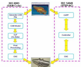
Over the last 15 years, many efforts have been made to apply STEP concepts to the data interface between CAD/CAM and CNC. The use of ISO 6983 (G&M codes) for programming CNC machines requires NC part programs to be specific to a machine and CNC controller. This is particularly true for the programming of asymmetric rotational parts manufactured on the wide variety of turn/mill centers. Through considering new standards, such as ISO 14649, this research explores the opportunity to enable STEP-NC part programs to be used for different turning centre configurations that provide a platform for interoperable manufacture. Both standards can be summarizing as shown in figure 1. To satisfy the latest requirements and demands with respect to a bi-directional process chain of machining modeling, several different technology-specific process models are necessary within STEP-NC. A new data interface framework for the milling process has been proposed in the OPTIMAL project to overcome the legacy standards of ISO 6983, informally named "G code" [4]. This is one of the earliest STEP-compliant systems and is based on feature information and machining strategies. The research does not
STEP Compliant CAD/CAPP/CAM System for
Turning Operations
stop there, because the researchers now focus on identifying and defining interoperable manufacturing and STEP-NC compliance in the context of concurrent engineering. In particular, information review of Standards for the Exchange of Product Model Data for Numerical Controls (STEP-NC), manufacturing processes, and manufacturing resources provide the basis for this paper. STEP-NC has been developed as a result of several research projects carried out by companies and academic institutions.
Figure 1: Comparison of the CAD/CAPP/CAM process chain with ISO 6983 and ISO 14649
Standardization and application are two identifiable STEP compliance research topics. In standards activities project names such as ISO, NIST, NCMS, ESPRIT Project, and IMS are recognized around the world [5, 6]. On the other hand for STEP compliant application, names such as STEP Tool (USA), WZL RWTH- Aachen and ISW Stuttgart University (Germany), National Research Laboratory for STEP-NC Technology (NRL-SNT), University of Bath and University of Auckland are among the established research groups [7]. The literature to date has provided an overall view of the various research projects carried out by the major research groups worldwide in the application of STEP-NC for CAD, CAPP, CAM and CNC integration, Xu, et al. [5]. Xu et al review the major global endeavors in STEP-NC related research such as the IMS STEP-NC project, European ESPRIT STEP-NC project, Super Model project, STEP Manufacturing Suite (SMS) project, Rapid Acquisition of Manufactured Parts (RAMP) project, Intelligent manufacture for STEP-NC-compliant machining and inspection with more technical insight. Other important aspects in that paper that have been discussed about work that has been carried out by research groups from countries such as Germany, Switzerland, UK, Korea, USA and New Zealand. One of the aims for next generation CNC machines is to be portable, interoperable and adaptable so that they can respond quickly to changes in market demand and the manufacturing needs of customized products and this is parallel with the STEP-NC manufacturing roadmap suggested by Suh [8]. The roadmap
consists of three steps to consider for the
STEP-Manufacturing environment; 1) participation with
many manufacturing related companies, 2) inducement toward an information oriented and international environment and finally, 3) consideration of compact and economical research and development [9]. The year 2006 was a time when researchers were extremely focused on this particular area, and details can be found a special issue edition of IJCIM for STEP-Compliant Process Planning and Manufacturing. Most of the researchers proposed a system framework to support data interoperability between the various CAx systems based on ISO standard 14649 that provided the first data exchange format used in the operation of a NC machines. That development of a future manufacturing platform to enable different process models to be integrated for the adaptable integration of CAD/CAPP/CAM and CNC will be a major avenue of research for years to come.
III. PROPOSED STEP COMPLIANT SYSTEM FOR TURNING OPERATIONS (SCSTO)
A STEP -NC compliant CAD/CAPP/CAM prototype system for turn/mill operations is being developed to consider the complexity of turning centre configurations and is based on STEP-NC turning features [10]. This prototype termed SCSTO has built using JBuilder 2005 and the JDataStore database. Tasks and major functions of this system is divided into definition of the: i) workpiece, ii) manufacturing features, iii) turn/mill operations, iv) project set-up, v) functional/technology, vi) manufacturing strategies, vii) placements/lengths and viii) tools [11].
A. Turning Classes
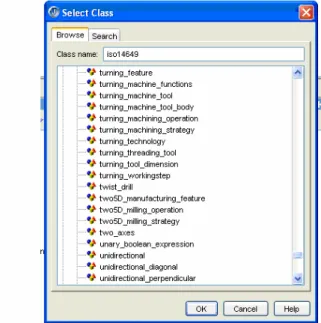
The process data for turning is provided in ISO14649 Part 12 [12] which specifies in the technology specific data elements that are needed as process data for turning [2]. Part 10 describes the general process data [8]. Included in Part 12 are features and operation data models for conventional turning, involving X and Z axis movements. This again only represents the standard rotational turning with no representation of features and operations for composite machining such as C-axis milling operations. Figure 2 shows example turning classes based on ISO 14649. This system needs integrated manufacturing information about the product model and manufacturing resources, and is also based on an object oriented platform. Another aspect of information is the description of the manufacturing process, and the product geometry that can be created and manipulated. The structured model approach, in the STEP-NC manufacturing chain starts with the definition of the feature-based design geometry in a CAD/CAM system. An ISO 10303 Part 21 physical file is then generated from a STEP-NC Compliant CAPP/CAM system based on a suite of Java information classes from the
STEP-NC ARM model definition, developed by
software proprietary format .MPF file [1]. The generated file can then be directly machined on any CNC workstation equipped with a Siemens controller and ShopTurn CAM software.
Figure 2: Turning classes based on ISO 14649
Figure 3: Operational structure of SCSTO
B. Information Model
The implementation of SCSTO consists of three main stages, namely the representation of the information model, the development of the tool database and the construction of the system application as shown in figure 3. The first stage starts with the proposed system framework for SCSTO
including an information model designed from the STEP-NC standards. The framework described mainly by the information and functional perspectives of the CAD to CNC process chain. The information model was established by Molina [13] and consists of a product model and a manufacturing model. The product model represents relevant information about the product throughout its life cycle while the manufacturing model is defined as an information model that identifies information describing the manufacturing resources, processes and strategies. The system has been modeled using the unified modeling language (UML) which clearly shows the system information model in terms of classes, attributes, relationships and operations. Various objects in the SCSTO environment and the relationship between these objects. Each of the entities is based on ISO 14649 Part 10, 11, 12, 111 and 121 [12, 14-17] The class diagram depicting various classes of product and process data types was created using Rational Rose version 2000. The second stage in constructing the SCSTO is the database system developed using JDataStore. In SCSTO the cutting-tools database involved both turning and milling tools. The process starts with creating a file, establishing connection, test query and database development.
C. Turning Operations
T urning schema, definitions of technology specific data types representing machining features and processes for turning operation on lathes are defined with reference to the ISO standard [12]. The turning operation has two basic categories of machining operation; either roughing or finishing. All the turning operations are under the machining_operation sub class which is based on the operation class. In turning the workingsteps include manufacturing features and machining operations are defined byturning_featureandturning_operationsrespectively. The UML representation was developed for the diagrams, the constraints and the extension mechanisms. UML is the most widely known and used standardized notation for object-oriented analysis and design. The most useful standard UML diagrams are; use case diagram, class diagram, sequence diagram, state chart diagram, activity diagram, component diagram, and deployment diagram. For the purpose of this research, only class diagrams and their notation were used. The UML diagram represents the various objects in the turning manufacturing environment and the relationships between these objects. Each data type in these models is based on ISO 14649 Part 10 and Part 12 [12, 13]. A class diagram illustrating how the object identifies itself through a set package of ISO 14649 for manufacturing features consists of fields, constructors and methods using the Java programming approach. The Java programming language was used for the development of software components based on an object oriented methodology and UML was utilized as the modeling language.
D. Graphic User Interface (GUI)
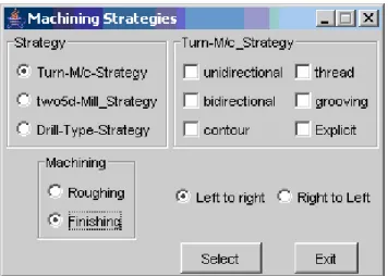
21 File. It mainly seeks inputs from the system users via dialogs, either by selecting from standard data or keys in dialogs. The process begins with defined turning features; turning operations, turning strategies, tooling and code generation. The user can also define their own data or edit and modify their own data. The project dialog is the first dialog that appears on the screen when a new project is created and this is the starting point of the data input process. This dialog continues with a link to the workpiece dialog and workplan dialog according to the SCSTO scheme by selecting the various options featured in a java combo box. After workpiece and workplanentity entry have taken place, the next entity considered is the turning feature. Figure 4 illustrates theturning_machine_strategydialog depicting the various attributes of the turning strategy entity.
Figure 4: Turning Machining Strategy dialog
Illustrations in this dialog were helping the user to get some ideas of the machining strategy chosen. Next, the machining workingsteps, which are characterized by the turning_machining_operation, define all the machining operations and technology specific data needed to define a turning operation. The data is captured via manufacturing operation, machining strategies, turning technology and the machine function dialog. The output of SCSTO is a text file that is compliant with the ISO 10303-21 physical file format. The overall structure of SCSTO is illustrated in figure 5 including the output STEP file.
IV. CASE STUDY COMPONENT
An industrially-oriented case study component representing a selection of operations and features has been used to illustrate and demonstrate the system. The case study component was adapted from component photographs in the Mazatrol brochure.
The component consists of turning features defined in STEP terminology namely: out diameter to shoulder, revolved flat, revolved round, grooves, thread and milling features, such as the revolved surface of the component. The constituent features of the component are shown in figure 6 where the features are not arranged in any particular hierarchy. The main reason for choosing this component is that it provides an introduction to the addition of milled features. This configuration represents the first level of turn/mill CNC turning for just the X, Z and C axes as found for example in the Okuma and Homa model HL35M.
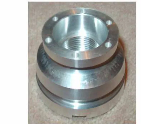
Milling operations are allowed on the side and face of component. Parts requiring a second set-up are manually rotated and positioned and re-held in the chuck in relation to first set-up operations unless the machine has the capability of a counter spindle to machine the other side with single set-up. Overall configuration for range 2-5 axes turning centre for machining this component. The machining operations for this case study component consist of turning, grooving, threading, off centre drilling and milling on side face. In terms of general attributes the component is double sided asymmetrical. The final component is shown in figure 7.
Figure 6: Turning centre configuration for case study component
Figure 7: Case study component.
I. CONCLUSION
This paper has outlined current CAPP and CAM systems related to STEP-NC that have been created by other worldwide researchers and illustrated the proposed STEP-NC compliant CAD/CAPP/CAM system that is currently being implemented by the authors. The system was constructed using a structured methodology in the initial stages and using object oriented methods for subsequent stages. SCSTO was developed to generate a Part 21 file automatically based on machining features to support the interactive generation of process plans utilizing feature recognition and includes the physical file. Efforts are under way to fulfill the STEP-NC challenge by combining Parts 11 and 12, for turn/mill operations. STEP-NC forms a possible basis to satisfy the
latest requirements and demands with respect to a bi-directional CAx process chain for machining. In addition its development as a future manufacturing platform to enable different process models to be integrated for the adaptable integration of CAD/CAPP/CAM and CNC will be a major avenue of research for years to come.
REFERENCES
[1] Nassehi, A., R.D. Allen, and S.T. Newman.Intelligent Replication of Manufacturing Information between CAD/CAM Systems and CNC Controllers. inProceedings of the 16th International Conference on Flexible Automation and Intelligent Manufacturing Conference (FAIM2006). 2006. Limerick, Ireland, June 2006.
[2] Newman, S., Integrated manufacture for the 21st century Development of the STEP-NC standard and its implications for manufacturing processes worldwide. Metalworking Production, 2004. 148(6): p. 13-16.
[3] ISO, International Organization for Standardization - ISO 10303-1:1994, Part 1: Overview and fundamental principles . Product data representation and exchange. 1994.
[4] ESPRIT,Project 8643, Optimized preparation of manufacturing information with multi-level CAM-CNC coupling (OPTIMAL): final report for publication.1997.
[5] Xu, X.W., et al.,STEP-Compliant NC Research: The search for Intelligent CAD/CAPP/CAM/CNC Integration.International Journal of Production Research, 2005. 43(17): p. 3703-3743.
[6] Xu, X. and S.T. Newman,Making CNC Machine Tools More Open, Interoperable and Intelligent.Computers in Industry, 2006. 57(2): p. 141-152.
[7] Xu, X.W. and Q. He,Striving for a total integration of CAD, CAPP, CAM and CNC.Robotics and Computer-Integrated Manufacturing, 2004. 20(2): p. 101-109.
[8] Suh, S.-H. and B.E. Lee. STEP-Manufacturing roadmap. in
Proceedings of the 2004 Society of CAD/CAM Engineers. 2004. Kangwon, Korea.
[9] Suh, S.-H., et al.,STEP-compliant CNC system for turning: Data model, architecture, and implementation.Computer-Aided Design, 2006. 38(6): p. 677-688.
[10] Yusof, Y., et al. The Design of a STEP-NC Compliant CAD/CAPP/CAM System for the Manufacture of Rotational Parts on a CNC Turning Centre. inProceedings of the 23rd International Manufacturing Conference (IMC23). 2006. University of Ulster, Northern Ireland, UK: University of Ulster.
[11] Yusof, Y., et al.A STEP Compliant System for Turning Operations. in 17th International Conference on Flexible Automation and Intelligent Manufacturing (2007 FAIM). 2007. Philadelphia, USA. [12] ISO, International Standard 14649-12: Part 12 : Industrial
automation system and integration - Physical device control - Data model for computerized numerical controllers - Part 12 : Process data for turning. 2005.
[13] Molina, G., A Manufacturing Model to Support Data Driven Applications for design and manufacture, in Manufacturing Engineering. 1995, Loughborough University: Loughborough. p. 330.
[14] ISO, International Standard 14649-10: Part 10 : Industrial automation system and integration - Physical device control - Data model for computerized numerical controllers - Part 10 : General process data. 2004.
[15] ISO, International Standard 14649-11: Part 11 : Industrial automation system and integration - Physical device control - Data model for computerized numerical controllers - Part 11 : Process data for milling. 2004.
[16] ISO/FDIS,Industrial automation systems and integration - Physical device control Data model for computerized numerical controllers -Part 111: Tools for milling machines.2004.