WIFI INDOOR POSITIONING FOR MOBILE DEVICES, AN
APPLICATION FOR THE UJI SMART CAMPUS
WIFI INDOOR POSITIONING FOR MOBILE DEVICES, AN APPLICATION
FOR THE UJI SMART CAMPUS
Dissertation supervised by
PhD Francisco Ramos Romero PhD Michael Gould Carlson MSc André Figueiredo Barriguinha
ACKNOWLEDGMENTS
This research project would not have been possible without the support of many people. Prof. Dr. Francisco Ramos who was abundantly helpful and offered invaluable assistance, support and guidance.
Deepest gratitude are also due to the members of the supervisory committee, Dr. Michael Gould and MSc. André Figueiredo.
Special thanks also to the Assoc. Prof. Andrés Muñoz who was offered some help during the project development of the work.
Special thanks also to all my graduate friends by all experiences together throughout the master specially to Alberto Olivares for his support in some difficult moments and for his friendship.
Not forgetting Paula Oliete who always been there.
""""I have not failed. I've just found 10,000 ways that won't work.
I have not failed. I've just found 10,000 ways that won't work.
I have not failed. I've just found 10,000 ways that won't work.""""
I have not failed. I've just found 10,000 ways that won't work.
Thomas Alva Edison
""""If I had eight hours to chop down a tree, I'd spend six sharpening my
If I had eight hours to chop down a tree, I'd spend six sharpening my
If I had eight hours to chop down a tree, I'd spend six sharpening my
If I had eight hours to chop down a tree, I'd spend six sharpening my ax.
ax.
ax.""""
ax.
WIFI INDOOR POSITIONING FOR MOBILE DEVICES, AN APPLICATION
FOR THE UJI SMART CAMPUS
ABSTRACT
Smart Campus has emerged as a study platform of a Smart City. There are some
similarities between the Campus and a City. Due to this, is possible use a Smart
Campus as attesting bench and then apply these investigations to implement in a
Smart City. One of this potential technologies is the Indoor Positioning System
using the Wi-Fi network. The aim of this work is research and implement a
mobile application to carry out the indoor positioning in the context of the UJI
Smart Campus. The prototype developed allows to perform the first part of the
Wi-Fi Indoor Positioning, the mapping phase. This application implements a
system to display and all UJI cartography (campus basemap, UJI buildings and
UJI buildings interiors). When whole system will be developed, it will allow
viii
KEYWORDS
Smart City Smart Campus GIS Applications
Geographical Information System Wi-Fi Indoor Positioning System Wireless positioning
Indoor Positioning Indoor Localization Smart Phones
ACRONYMS
A-GPS Assisted GPS (see GPS) AOA Angle of Arrival
AP Access Point
API Application Programming Interface
BSSID Basic Service Set Identifier, same as MAC in value Cell-ID Cell Identification
dBm Decibel miliwatt
GNSS Global Navigation Satellite System GPS Global Positioning System
ICT Information and Communication Technologies IEEE Institute of Electrical and Electronics Engineers INIT Institute of New Imaging Technologies
LAN Local Area Network LOS Line of Sight
MAC Medium/Media Access Control, same as SSID in value REST Representational State Transfer
RFID Radio Frequency Identifier
RSS(I) Received Signal Strength (Indication) SDI Spatial Data Infrastructure
SDK Software Developer Kit SQL Structured Query Language
SS Sum of Squares
SSID Service Set Identifier TDOA Differential Time of Arrival TOA Time of Arrival
UI User Interface UJI Universitat Jaume I
UMTS Universal Mobile Telecommunications System UNIX Uniplexed Information and Computing System URL Uniform Resource Locator
US United States
UWB Ultra Wide Band
viscaUJI Virtual Smart Campus for the Universitat Jaume I WAP Wi-Fi Access Point
Wi-Fi Wireless Fidelity
WIPS WiFi Indoor Positioning System WLAN Wireless LAN (see LAN)
TABLE OF CONTENTS
PART O: INTRODUCTION
1-. INTRODUCTION ... 3
2-.GOAL/OBJECTIVES AND SCOPE/LIMITATIONS ... 6
PART I: THEORETICAL FRAMEWORK
3-. SMART CAMPUS ... 93.1. Smart Cities and Smart Campus ... 9
3.2. GIS in Smart Campus ... 10
4-. MOBILE PLATFORM ... 13
4.1. Introduction ... 13
4.2. Android ... 14
4.3. ArcGIS SDK for Android ... 15
5-. SENSORS AND POSITIONING TECHNIQUES ... 16
5.1. Available sensors technologies ... 16
5.2. Positioning technologies ... 17
5.2.1. Self positioning techniques ... 17
5.2.2. Remote positioning techniques ... 19
5.3. Indoor wireless positioning system using Smart Phones ... 23
PART II: PROJECT OVERVIEW AND DESIGN
6-. GOAL, OBJECTIVES AND SCOPE ... 277-. DESIGN REQUIREMENTS ... 28
8-. DESIGN ... 30
9-. MOBILE PLATFORM ... 32
10-. POSITIONING TECHNIQUE ... 33
11-. SERVER PART ... 34
12-. CLIENT PART ... 39
12.1. Software System Design ... 39
12.2. Registering Fingerprints ... 51
xii
PART III: CONCLUSION
14-. CONCLUSIONS ... 57
14.1.WIFI INDOOR POSITIONING ... 57
14.2. ARCGIS SDK ANDROID ... 57
14.3. SMART CAMPUS ... 57
PART
IV: FUTURE DIRECTIONS
15-.FUTURE DIRECTIONS ... 61PART V: BIBLIOGRAPHY
16-.BIBLIOGRAPHY ... 65PART VI: ANEXES
17-. ANEXE I: SOURCE CODE ... 7117.1. Clases... 71
17.2. Layout ... 96
INDEX OF TABLES
xiv
INDEX OF FIGURES
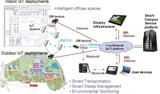
Figure 1: Outline the architecture of a smart campus (Surrey) ... 3
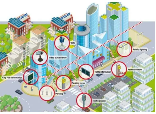
Figure 2: Smart City technologies (Ingeniería para optimistas) ... 4
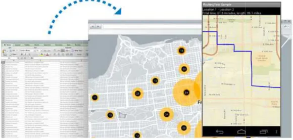
Figure 3: Place-Finder web-app of the viscaUJI project (Geotec) ... 4
Figure 4: Logo of Smart UJI ... 11
Figure 5: Mobile platforms (Poder PDA) ... 13
Figure 7: Android logo (Wikipedia) ... 14
Figure 8: ArcGIS Runtime SDK for Android (Resources ArcGIS) ... 15
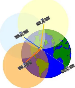
Figure 9: Scheme of GPS system ... 18
Figure 10: Time of Arrival ... 20
Figure 11: Differential Time of Arrival ... 21
Figure 12: Triangulation ... 21
Figure 13: Allocation methods based on Woo et al. (2011) ... 22
Figure 14: General schema of the system designed ... 30
Figure 15: Service directory of the Geotec server ... 35
Figure 16: MasterGeotec server, inside the folder of this project... 35
Figure 18: UJI Buildings interior by floor ... 36
Figure 17: a) UJIBuildings; b) viscaUJI desaturado; c) viscaUJI ... 36
Figure 19: Diagram of the Geodatabase Architecture ... 38
Figure 20: Activity lifecycle (Android developer) ... 40
Figure 21:Use Case Diagram ... 40
Figure 22:Scheme of the class IndorPositioning ... 41
Figure 23: Main screen of the application, displayed by an emulator ... 42
Figure 24: Application menu with the options: "Select BaseMap", "Add Buildings Interiors Layer", "Select Floor" and "About" ... 42
Figure 25: Select BaseMap dialog ... 43
Figure 26: Application displaying the Grey Map ... 43
Figure 27: Select Building Interior Layers dialog ... 43
Figure 28: Displaying the building Interiors, floor 0 ... 44
Figure 29: Select Floor dialog ... 44
Figure 30: Displaying of the second floor ... 44
Figure 31: About dialog ... 45
Figure 32: "MyTouchListener" main schema of the application ... 46
Figure 34: Antenna Layer becomes visible in the application ... 47
Figure 33: Scheme of the Add Antenna function ... 47
Figure 35: List of antenna names in the application ... 48
Figure 36: A new graphic appears where the user have touched on the map ... 48
Figure 37: Main scheme of the Add Wi-Fi Fingerprint function ... 49
Figure 38: Wi-Fi Scan Points measureds by the user ... 50
Figure 39: Visualization of the Scan Points and the grid through ArcMap ... 51
Figure 40: Different interfaces of the training phase of the application. Visualization of theUJI buildings and building interiors ... 52
Figure 41: Attribute table of the Wi-Fi Scan Points ... 53
PART 0 - INTRODUCTION
CONTENTS
1-.INTRODUCTION
2-.GOAL/OBJECTIVES AND SCOPE/LIMITATIONS
SUMMARY
In this part, it is going to do a introduction of the project by outlining and framing the project. It starts talking about the campus as a platform concept that it will briefly explain the concept of Smart Campus and then it will explains the importance and scope of the location based services applied as a Smart Campus service.
Introduction
1-. INTRODUCTION
A campus is a platform whe at week. These people have staff and campus manag (energy, maintenance, info reasons the campus platfor Optimize the resources a managers. Regarding the im data that the campus adm way, most of the campus inFigure 1: Outline the
The concept of Smart Camp to improve the services a services and it’s a power transports, access, classroo Besides this is possible to u investigations to implement
ION
where there are people spending same hours at a da have a different role in the campus (students, profes
nagers/administrators). This platform has differe information, etc. expenses) and offers same servic tform and the city platform have several similarities.
s and improve the services is a key factor for he improvement of the services in a campus, abou administration works with daily are georeferenced. s information that the students use are georeferenc
e the architecture of a smart campus (Oredope, Gluhak, & Evan
ampus appears in order to use the new technologie es and reduce the expenses. Smart Campus can werful tool to manage all information in a cam srooms and labs, energy expenditure, maintenance in
to use the smart campus as attesting bench and the ent smart cities with tested applications and with a
a day many days ofessors, campus fferent expenses rvices. For these ities.
for the campus bout 80% of the ced. In the same renced too.
Evans)
ogies and apply it can improve all campus: wastes,
Introduction
Joan Pere Avariento Vicent Figu
The Smart UJI project is c growing adding different ki geodatabase (a database w tools developed, most of geodatabase needs add m other information that will
Figure 3: Pl
An important part of any S application that use the n becoming a part and parce
cent
Figure 2: Smart City technologies (Pareja, 2012)
is called viscaUJI project. This project is actually nt kind of services and applications. Nowadays the se with geographic data and alphanumeric data) a
of them developed with web technologies. H d more data, such as buildings data, building inter will be useful in the future.
: Place-Finder web-app of the viscaUJI project (Geotec)
ny Smart Campus or any Smart City is the realization he new technologies. Nowadays the Smart Phon arcel of lives of most peoples. These are the reason
4 lly working and the project has a ta) and different s. However the interior data and
Introduction
Campus needs mobile appl services.
Technological advances wit of personal locating techn Global Position System (GP watercraft. As computing a including Garmin Ltd., TomT systems with increased usa mounted, handheld, and w current location and find measurements of signals internet (Wi-Fi) access poin becoming ubiquitous in the technologies into the Sma dedicated to positioning o computing systems on th readdressing problems that The signals used by outdoo Systems that rely on the nearby Wi-Fi access points the individual rooms of a b but are unreliable indoors and other objects.
Due to these limitations, Campus is necessary the positioning a user inside th and fundamental tool of th maintenance breakdowns…
application to provide to the Smart Campus user's to
within the past decade have caused a surge in the hnologies. Early consumer grade locating systems m (GPS) receivers fit for mounting on automobiles, ing and communication technologies have advanced
omTom International, and Magellan Navigation Inc. usability and functionality. Current systems on th d wristwatch scales provide users the ability to det nd their way to their destination. Today’s advanced als from GPS, cellular communication towers, points to locate the user. Internet enabled mobile
the personal and business marketplaces. Integratio mart Phones has made the use of handheld dev ng obsolete. The availability of powerful commu n the handheld scale has created many oppo that have historically been solved in other ways.
tdoor locating technologies are often inadequate in the use of cellular communication signals or ide ints do not provide sufficient accuracy to discrimin f a building. GPS based systems can achieve sufficie
ors due to signal interference caused by walls, floo
ns, and the need of this kind of applications by vi the study, research and implement an applica e the buildings in the UJI campus. This application w of the other applications such as navigation, place
ns…
r's tools and new
the proliferation ms manifested as iles, aircraft, and nced, companies Inc. have offered n the dashboard determine their ced systems use rs, and wireless obile devices are ration of locating devices that are munication and pportunities for
te in this setting. identification of iminate between fficient accuracy, floors, furniture,
Introduction
Joan Pere Avariento Vicent
2-.
GOAL/OBJECTI
The main objective of thi technologies as a positioni will be developed to provid The secondary objective is t to perform the Indoor Posit to develop other applicatio navigation application, plac The framework of the app reason, the application mu whole project. In fact, all viscaUJI project, but this wi For all of the above, the ap the project), and store the be integrated to the main g The academic objective of Geospatial Technologies. months.
cent
JECTIVES AND SCOPE/LIMITATIONS
f this work is research whether is possible to u tioning technique for Smart Phones. This positioni ovide the position inside the UJI campus buildings. e is the implementation of a mobile application that Positioning. This application will be a basic tool or a
ations that will need incorporate the indoor positio place finder, notice maintenance problems…
application is the UJI Smart Campus project: visca must be compatible with the others mobile appli all of these applications will be integrated in only
s will be in the future.
e application must use the viscaUJI data (use the ge the data in a compatible format probably because
in geodatabase in the future.
of this work is performing the Master’s Thesis of t s. Consequently it is a requisite perform the wo
6 o use the Wi-Fi ioning technique
that will be a tool r a basic module sitioning such as
viscaUJI. For this pplication of the only one for the
e geodatabase of use this data will
PART I – THEORETICAL
FRAMEWORK
CONTENTS
3-.SMART CAMPUS
3.1. SMART CITIES AND SMART CAMPUS 3.2. GIS IN SMART CAMPUS
4-.MOBILE PLATFORM 4.1. INTRODUCTION 4.2. ANDROID
4.3. ARCGIS SDK FOR ANDROID 5-. SENSORS AND POSITIONING TECHNIQUES
5.1. AVAILABLE SENSORS TECHNOLOGIES 5.2. POSITIONING TECHNOLOGIES
5.2.1. SELF POSITIONING TECHNIQUES 5.2.2. REMOTE POSITIONING TECHNIQUES
5.3. INDOOR WIRELESS POSITIONING SYSTEM USING SMART PHONES
SUMMARY
Theoretical Framework
3-. SMART CAMPUS
3.1. Smart Cities and
The XXI century is called advanced with giant steps important thing in the citi sustainability point of view wastage and losses (Hernán is a platform where the p business and in this context For these reasons the publ think about the manageme the municipal managers, th better automatic and efficie This will provide some bene The Smart Cities is a good informatics and communica efficient infrastructure and The Smart City becomes environment and welfare behavior among all stakeh maximize public budgets, p in the city and its inhabit cooperation strategies amo and innovation resources tools, methodologies and Future Internet technologie innovation resources as we will constitute the future ba opportunities provided by Trousse, Nilsson, & Oliveira Smart City has to pay atte development. People needPUS
s and Smart Campus
lled to be the century of the cities because the teps (Shapiro, 2005). Also, optimize the resource cities. Smart cities purpose rethink about the cit view: adjust all of resources demand, reduce th rnández Muñoz, 2011) (Caragliu, Del Bo, & Nijkamp, he people live and work, where the companies d
text there are many services managed by the city ha public administrator, in this case the local administ ement of the evolution of cities models. From the rs, that provides services to the city, have a Smart fficient management of the urban infrastructures an
enefices: expenditure reduction and improvement o ood solution to address these facts. The Smart Cit
nication technologies and tries to create a more in nd their components and services.
es a digital platform that maximizes the econo are of the cities, and facilitates the shift to more keholders: users, businesses and government. It a ts, precisely thanks to the improvement of the proce
abitants (Fundación Telefónica, 2011). Partnershi among main stakeholders are needed in order to sh ces such as: experimental technology platforms, e nd know-how, and user communities for experim logies and e-service applications. Common, shared s well as cooperation models providing access to su re backbone of urban innovation environments for e by Future Internet technologies (Schaffers, Kom eira, 2011).
attention to the role of social and relational cap eed to be able to use the technology in order to be
the urbanization urces will be an e cities from the the waste, the mp, 2009). A city ies develop their
y hall.
inistrator, has to the viewpoint of art City helps a es and resources. ent of services. t City applies the
e interactive and
conomy, society, ore sustainable It also seeks to rocesses involved rships and clear to share research s, emerging ICT erimentation on red research and o such resources for exploiting the omninos, Pallot,
Theoretical Framework
Joan Pere Avariento Vicent From the viewpoint of mu automatic and efficient m advantages: first, the reduc self services (Fundación Tel There are a parallelism be these characteristics and a smaller than a city but it is improvement in the manag campus. Due to these char bench (Sanchis, y otros, 201 The Smart Campus offers campus managers have sev services, the resources and role of social in the campus to benefit from it and for th
3.2. GIS in Smart Cam
About 80% of the data that georeferenced (Coll, Mart administrations have prove System (GIS)in the municip this data (Coll, Martínez, & (Martínez, Coll, & Irigoyen,However, there are more p the campus staff doesn’t kn use together because is st between data of the differ data is not related with his
The GIS provides solution information. The Spatial D the tools to access to the ne users to do analysis on the 2012). This local SDI in the and single.
cent
municipalities provided in the city, have a Smart nt management of urban infrastructure, which eduction of expenditure and secondly the improvem
Telefónica, 2011).
between a city and a university campus and it is nd applies the smart city concept in a campus. Th
it is more controlled. The concept of Smart Camp anagement of the resources and the facilities in the
haracteristics it is possible to use the Smart Campu , 2012).
fers several improvements for whole campus com several tools to manage, analyze and take decisio and the campus facilities. The campus has to pay att pus. The students need to be able to use the techno or the own campus (Caragliu, Del Bo& Nijkamp).
t Campus
that the campus administration and campus staff w artínez, & Irigoyen, 2005). The same experien roved that the gradual incorporation of a Geographic icipal databases are the best way and the best tool ez, & Irigoyen, 2004) (Coll, Martínez, Ibarz, & Elg
en, 2004) (Peñarrubia & Rubio, 2007).
re problems in the administration related with the ’t know well the spatial data; the spatial and numeri is stored in incompatibles formats; there aren’t co ifferent departments; there are redundant data; t his spatial data (Coll, Martínez, Ibarz, & Elgezaba, 20
tions to visualize and integrate global and local al Data Infrastructure (SDI), in the distributed vers e needed information in an interoperable way. Thes n the different systems on the smart campus (San
the Universitat Jaume I (UJI) is viscaUJI. The data
10 art City help the ich has obvious vement of one’s
it is possible use The campus is ampus means an the frame of the mpus as a testing
community. The cisions about the y attention to the chnology in order
works daily are rience in these phic Information tool to work with Elgezaba, 2007)
the spatial data: erical data can’t t communication ta; the numerical a, 2007).
Theoretical Framework
The viscaUJI project improv is based in a SDI local mo viscaUJI GIS is the most pow the analysis of the differen any kind of application or se
Figure 5
ViscaUJI integrates all info
Figure 4: Logo of Smart UJI
proves the resource management on the UJI campus l model and integrates all available information i t powerful tool to manage the campus data and it is erent systems in a campus. This GIS is the best bas or service for staff and students.
5: A version of UJI data model (Sanchis, et al., 2012)
information (geographic and alphanumeric) follow
pus. This project on in a GIS. The it is a tool to do base to develop
Theoretical Framework
Joan Pere Avariento Vicent campus enables a set of se These services are offered t
• Web Map Service (W • Gazetteer Service • Catalog Web Servic
cent
of services to provide data to the applications that ed through internet and there are:
ce (WMS)
rvice (CWS)
Theoretical Framework
4-.
MOBILE PLATF
4.1. Introduction
A mobile platform is a por which a user can perform Internet access. In recent devices, large and heavy, more new functions that ar increase their functionality platforms that are implem Symbian, UNIX, Apple and source platform. Symbian a respectively. Apple develo figure shows the mobile plaFor each platform, Softw producer to help third pa platform. To protect the c developer is able to acces Application Programming In
LATFORM
portable device, typically a mobile phone or a sma form different functionalities such as cellular net ent years, mobile phones have evolved greatly si vy, designed only for phoning anywhere. There a at are being added to the current generation of mob
ality and productivity. There are currently four plemented directly or developed by other highe and Windows. Among these platforms, only UNIX ian and Windows are licensed by Nokia Inc. and M velops and distributes the mobile operating syste
platforms that are actually in the market:
Figure 6: Mobile platforms (Poder PDA)
ftware Developer Kits (SDKs) are provided by party developers create applications for use on he closed source of the structure of the operating ccess different functionalities of the operating sys ng Interfaces (APIs).
smart phone, on etworking and ly since the first re are more and mobile device to popular basic igher platforms: UNIX is an open d Microsoft Inc., ystem iOS. Next
Theoretical Framework
Joan Pere Avariento Vicent
4.2. Android
The main operating system because there are the tw comparison between Andro ANDORID
68% worldwide market of S Is incorporated in multiple S Allow custom and access wh
Table 1: C
Android is the operating sys reasons for choosing Andro Android…
is an easy programm is open source. has an efficient man has a large commun Thus was born Android. An on Linux for Smartphone environment of Java applica others operating systems is widgets, or even modifies
Figure
cent
stem to target the application of this work are And e two main mobile operating systems. Next ta ndroid and iOS.
iOS
of SmartPhones 17% worldwidemarket of Sma ple SmartPhones iOS is only available by Apple ss whole system iOS does not allow that
: Comparative between Android and iOS (Luna, 2012)
g system selected to develop and implement this wo droid are:
amming language if one has previous knowledge of management of the available resources.
munity of developers and users.
. Android is an operating system and a software pla hone and tablets. Android lets you program in plications. Moreover the most important difference
s is that anyone who can program can create new the operating system itself because is open sourc
gure 7: Android logo (Wikipedia)
14 Android and iOS t table shows a
SmartPhones ple
is work. The main
e of Java or C #.
e platform based in a working nce between the new applications,
Theoretical Framework
4.3. ArcGIS SDK for A
ArcGIS Runtime SDKs for S that utilize the powerful m provided by ArcGIS for serv maps and tasks into the apFigu
The most powerful capabi follow:
• Use and display ser • Execute sophisticat • Create applications • Use a rich set of ta in the application a • Work with the devi • Perform advanced g
for Android
or Smart Phones enable to develop users to build ful mapping, geocoding, geoprocessing and custom server. Using this SDK, the user has the ability to e
application.
Figure 8: ArcGIS Runtime SDK for Android (ESRI)
pabilities that ArcGIS SDK provides to the applicat
services from ArcGIS Online and/or ArcGIS for Serve ticated geoprocessing tasks and displays results.
ions that collect data and update data.
f tasks which leverage the power of ArcGIS to anal on and provide information to the application’s users device GPS mobile.
ced geometric operations locally.
uild applications stom capabilities to embed ArcGIS
lications are the
erver.
Theoretical Framework
Joan Pere Avariento Vicent
5-.
SENSORS AND
5.1. Available sensor
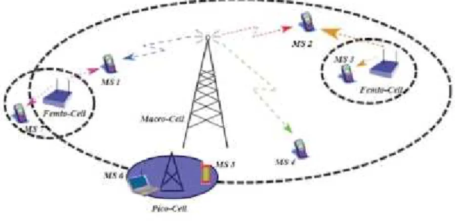
There are many Location B needed of a precise indoor GPS (Martin, Vinyals, Friedl integrated in a mobile plat technologies are GPS, Cell T The Bluetooth and Infrared implementation, the low ra A Cellular Communication communicate with each ot mobile devices. The range of large buildings, trees a tower is 35 kilometers in an ID, also called Cell of Origin Giaglis, & Lekakos, 2003) estimate the position of a c at a specific time. The adv implementation and the fa technique is very low du kilometers or more. In urbaThe GNSS (Global Navigati global coverage. Currentl dedicated to the civil posi System), the Russian GLON advantage of satellite syste altitude to a high degree o functioning of these syste indoor environment where Wireless Fidelity (Wi-Fi) is t connectivity is more preva
cent
AND POSITIONING TECHNIQUES
ensors technologies
on Based Services running on the Smart Phones, b oor localization system, since most of these applica riedland, & Bajcsy, 2010). There are many potential platform that it is possible use to carry out the posit
ell Tower, Wi-Fi, Bluetooth and Infrared.
ared technologies have been discarded because the w range and the low range (Le, 2009).
ation Network is a system that allows mobile h other. This system uses large cell towers to wirele nge of cellular communication networks depends o
s and other possible obstructions. Maximum ran in an open rural area. This method is a basic techniq rigin, to provide location services for cell phone user 03). This method is based on the capability of the
f a cell phone by identifying the cell tower that the d advantage of this technique is its ubiquitous distr e fact that all mobile cell phones support it. The acc due to the fact that cell towers can support r urban environments cell towers are distributed more
igation Satellite System) provide geo-spatial positi ently there are several global navigation sate positioning including the US NAVSTAR GPS (Globa LONASS, and the European Union’s Galileo (Thursto systems is that receivers can determine latitude, lo ee of accuracy. However, LOS (Line Of Sight) is req ystems. This leads to an inability to use these sy
ere the LOS is blocked by walls and roofs.
) is the common nickname for the IEEE 802.11 stand revalent than ever in our everyday lives. Each wi
16 s, but there is a plications rely on tial technologies ositioning. These
the high cost of
bile phones to irelessly connect ds on the density range for a cell nique using Cell-users (Zeimpekis, f the network to he device is using distribution, easy e accuracy of this rt ranges of 35
ore densely.
ositioning with a satellite systems lobal Positioning rston, 2002). The e, longitude and required for the e systems for an
Theoretical Framework
broadcasts a signal that is capability to measure the s known as received signal s user’s device can detect the RSSI is a dimensionless met from multiple access point actual received signal str conversions include: The m the maximum and minim resolution of the conversion An advantage of Wi-Fi is th dense areas and are contin to have a lower cost of impl
5.2. Positioning tech
Positioning techniques can positioning (Zeimpekis, Gia terminal uses signals, tra position. In the second case measuring the signals trave be installed at one or more positioned. These signal m direction of the individua computed from geometric r 5.2.1. Self positioning tec GPS and Assisted GPS (A system. The system’s satell to determine its position. G As far as the A-GPS metho provider can assist the han by collecting data from the the handset itself may be u method can be extremely a Lekakos, 2003). Therefore G where there is a clear vie technologies to remedy the Li, 2003).t is received by devices in the area. Wireless devi he strength of this signal. This strength is converted nal strength indicator (RSSI) (Le, 2009) (Halder & K t the RSSI and MAC address of multiple routers at on metric that is used by systems to compare the stren oints. There is no standard conversion between l strength (RSS). Important characteristics of
e maximum and minimum RSSI values (dimensionl inimum RSS values that can be represented (dBm
ion (value in dBm represented by one RSSI unit), (L is that wireless networks are universal. They exist in
ntinuously spreading outward. This causes Wi-Fi b implementation (Le, 2009).
technologies
can be implemented in two ways: Self-positioning Giaglis, & Lekakos, 2003). In the first approach transmitted by the gateways/antennas to calcu case (remote positioning) the mobile terminal can b
avelling to and from a set of receivers. The receive ore locations measure a signal originating from the al measurements are used to determine the le ual radio paths, and then the mobile termina tric relationships.
ng techniques
(A-GPS): GPS is the worldwide satellite-based rad atellites transmit navigation messages, which a GPS n. GPS receiver processes the signals to compute p ethod is concerned, the mobile network or a third handset by directing it to look for the specific satel the handset to perform location identification calc be unable to perform due to limited processing powe
ly accurate, ranging from 1 to 10 meters (Zeimpek re GPS is largely unchallenged in the outdoor positio r view of the sky. There is still a need for oth y the serious shortcomings of GPS technology (Wan
evices have the ted to a number, & Kim, 2012). A
t one time. trength of signals
en RSSI and the of RSSI to RSS
ionless integers), dBm), and the
(Le, 2009). ist in population-Fi based systems
ning and remote ach, the mobile alculate its own an be located by eivers which can the object to be e length and/or inal position is
Theoretical Framework
Joan Pere Avariento Vicent GPS is a semi-accurate glob (Lenihan, 2004). The accura space. A GPS device canno blocked.
Methods have been develo pseudolite systems that im receiver within the buildin University GPS Lab, which system (Kee, Yun, Jun, P convergence time of under a mobile user. This system mobile vehicle in an indoor an inverse carrier phase d reference station is also fixe The system faces several ch strict pseudolite synchroniz through the use of a pulse s problem. The prototype ha However, this system is ver a large number of pseudolit Assisted GPS (A-GPS) is pr method uses assistance fr network, to assist the mob Also, data from the device not otherwise be possible some satellite signals are w
cent
Figure 9: Scheme of GPS system
global positioning and navigation system for outdoor curacy of GPS devices is still in the range of 5-6 me annot be used for an indoor environment becaus
veloped to overcome the LOS requirement of GPS t imitate GPS satellites by sending GPS-like correcti
ilding. A system has been developed by the Se ich achieves sub-centimeter accuracy for indoor GP n, Parkinson, Pullen, & Lagestein, 2001). This sy der 0.1 seconds, which helps to increase the respo stem uses pseudolites and a reference station to door environment. The pseudolites have a fixed pos se differential GPS to calculate the mobile user’s
fixed and transmits carrier phase correction to the al challenges including serious multipath propagatio onization requirements. The multipath propagatio lse scheme. Using a center pseudolite solves the syn e has achieved 0.14 cm static error and 0.79 cm dy very financially costly to implement, due to the req dolites.
s primarily used in cellular phones (Lenihan, 2004 e from a third party service provider, such as mobile device by instructing it to search for partic vice itself is used to perform positioning calculation ible due to limited computational power. A-GPS is re weak or unavailable. The cell tower provides info
18 door applications 6 meters in open cause the LOS is
PS by setting up rection signals to e Seoul National r GPS navigation is system has a sponsiveness for to assist a GPS position and use r’s position. The the mobile user. gation errors and tion is addressed e synchronization m dynamic error. requirement for
Theoretical Framework
assists the GPS receiver. W but suffers similar indoor lim Indoor Global Positioning S advantages of GPS for dev Indoor GPS solutions can be exist. Indoor GPS takes i requirements of wireless computers. The navigation satellites). The signal is de pseudolite-compatible rece receivers (Zeimpekis, Giagli
5.2.2. Remote positionin Cell Identification (Cell-ID) services and applications. T a mobile handset by knowin benefit is that all devices generally low (200 meters)
Figure 10: Cell
Angle of Arrival (AOA): det towards the receiver from calculating such information is unreliable, since it is pro the receiver, which us hard Time of Arrival (TOA): meas from the transmitter to the is a constant, only time n However, in order to get needed (Lenihan, 2004).
r. When using A-GPS, accuracy is typically around 1 or limitations to standalone GPS (Lenihan, 2004). ing System (Indoor GPS): This system focuses on e developing a location-sensing system for indoor e n be applicable to wide space areas where no signif es into account the low power consumption an less access devices, such as mobile phones an
tion signal is generated by a number of pseudoli is designed to be similar to the GPS signal in or receivers to be built with minimal modifications to iaglis, & Lekakos, 2003).
ioning techniques
ID): this method is the basic technique to prov s. The mobile networks can identify the approximat owing which cell site the device is using at a given tim ces support this technology but the accuracy of th ers) depending on cell size (Zeimpekis, Giaglis, & Leka
Cell Identification scheme (Liu, Zhang, Yi, Li, & Zhang, 2012)
determines the positioning of the user by measur from the transmitter. The transmitters must be ation. This can be done with directional antenna. Yet prone to multi-paths, plus it requires the line of si ard to counter in the harsh indoor environment (Len
easures the exact distance by using the travel time the receiver. Using the equation R = time x speed, e needs to be measured to determine the exac get more accurate results, synchronization of the
nd 10-20 meters
on exploiting the or environments. ignificant barriers and small size s and handheld dolites (pseudo-n order to allow
s to existing GPS
provide location imate position of n time. The main of the method is Lekakos, 2003).
asuring the angle t be capable of . Yet, the method of sight to detect (Lenihan, 2004). time of the signal
Theoretical Framework
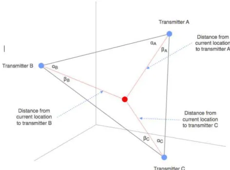
Joan Pere Avariento Vicent Differential Time of Arrival ( the locus of the time differ dimensional plane and hype a number of base stations t is similar to TOA subjec synchronization between ba
cent
Figure 11: Time of Arrival
ival (TDOA): The position is determined from the in ifference of arrival at the receiver, which is hyperb hyperboloid in three-dimensional space. A TDOA sys
ns that is one greater than the number of dimensio bjected to the time of arrival measurement an
n base stations in the system (Lenihan, 2004).
Theoretical Framework
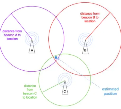
Triangulation: In an environ directly converted to distan the inverse of the square convert to distance in a rea objects in the signal path m the accuracy with which the
Location fingerprinting: Loc measured RSSI data to a Kumar-Raja, 2010). Typica around the building. A mul database for the best mat accurate but takes a long tim
Figure 12: Differential Time of Arrival
vironment with known propagation losses, signal str istance (Lenihan, 2004). In free space, signal strengt are of the distance from transmitter to receiver. T
real setting, factors such as antenna gains and inter ath must be accounted for. This method’s accuracy h the propagation losses can be estimated.
Figure 13: Triangulation
Location fingerprinting is a positioning technique th a database of expected values to estimate loca pically, measurements are taken in an arbitrary ultiple matrix correlation algorithm can be used t match, thus giving a position estimate. This meth
g time to implement.
l strength can be ength varies with er. To accurately nterference from racy depends on
Theoretical Framework
Joan Pere Avariento Vicent Figure
cent
re 14: Allocation methods based on Wooet al. (2011)
Theoretical Framework
5.3. Indoor wireless
The possibilities offered by communications and accele system within buildings h ubiquitous availability of hardware is required to ins 2010).Two basics methods of find are trilateration and locatio The trilateration method c strength data and know the Points (APs). The distanc proportional to the signal user’s location if at least 3 But this method of trilatera of the signals undergo vario like walls, equipments wit correct position of the user On the other hand, fingerp better accuracies. The mo between the measured rad registered in the radio map consists in two stages: Tr (Meng, Xiao, Ni, & Xie, 2011 Training phase, also called values from different bea between these chosen loca for indoor environments t Friedland, & Bajcsy, 2010) The other phase is called O through best matching bet recorded in the radio map make use of deterministic Bajcsy, 2010):
eless positioning system using Smart Phon
d by 3 available resources in smart phones: Wi-Fi ccelerometer. The use of Wi-Fi signals as a potentia gs has opened doors for many applications. Thiof Wi-Fi signals in almost all the buildings, so n install a positioning system in the buildings (Monoj
finding the position of the user given the signals stre ation signature/fingerprinting.
od can compute the user location on the fly fro the positions of the Wi-Fi signals transmitters also tance of the user from any Wi-Fi transmitter nal strength obtained from that transmitter. One t 3 Wi-Fi transmitters are visible.
teration does not work well in the indoor environm various interference and multipath problems due to within the building and so the trilateration will user. (Li, Salter, Dempster, & Rizos, 2006).
gerprinting techniques have already proved to be ab mobile terminal estimates its location trough be radio signals and those corresponding to location map (Martin, Vinyals, Friedland, & Bajcsy, 2010). Th : Training phase and online phase (Monoj-Kumar 2011), (Martin, Vinyals, Friedland, & Bajcsy, 2010).
lled offline phase, in which radio map of the area beacons are recorded at different locations; th locations will depend on the area in the study, and ts this separation can be of around a meter (Ma 0). The training data is stored in a database.
ed Online phase, in which the mobile terminal infer between the radio signals being received and tho
map. Localizations algorithms employed in this ca istic or probabilistic techniques (Martin, Vinyals,
t Phones
Fi radio, cellular ential positioning This is because so no additional onoj-Kumar-Raja,strength of Wi-Fi
from the signal also called Access tter is inversely One can find the
ronment because e to the features will not result in
e able to deliver h best matching ations previously . This technique mar-Raja, 2010),
rea is built. RSSI ; the separation and for instance, (Martin, Vinyals,
Theoretical Framework
Joan Pere Avariento Vicent Deterministic techniques s access points. The most rele
a) “Nearest neighb b) “Nearest neigh
and calculating
c) “Smallest polyg various polygon as the estimate d) “Naïve Bayes m
processed and being the user’s Then the point picked and decl
cent
es store scalar values of average RSSI measureme t relevant techniques in this group are:
ighbor in signal space”.
eighbor in signal space-average”, choosing k neare ting the centroid of that set.
olygon”, selecting several nearest neighbors whi ygons and the centroid of the smallest polygon will b
ated location.
es method”, the given set of signals at the user and the probability of the each and every point in ser’s location is calculated using the probability den oint with the highest probability of being the use declared as the user’s location (Monoj-Kumar-Raja, 2
24 ements from the
earest neighbors
PART II – PROJECT OVERVIEW
AND DESIGN
CONTENTS
6-.GOAL, OBJECTIVES AND SCOPE 7-.DESIGN REQUIREMENTS 8-. DESIGN
9-. MOBILE PLATFORM 10-. POSITIONING TECHNIQUE 11-. SERVER PART
12-. CLIENT PART
12.1. SOFTWARE SYSTEM DESIGN 12.2. REGISTERING FINGERPRINTS 13-. RESULTS
SUMMARY
Project Overview and Desig
6-.
GOAL, OBJECTIV
The main goal of this syste the framework of the vis applicable to the others sub The goal of the applicatio positioning. The indoor trilateration and fingerprint the offline part of these two The system will be easy connectivity. The system w system and methods, and campus.To function as intended, the The application mu Indoor Positioning S The application m data in a server to u The device must ha The mobile applica viscaUJI project and This system must b Campus project. The scope of the project is f in an indoor location based the other hand the applica the UJI Smart Campus. The ambit of the project is an indoor location based se the architecture of the geo server, ArcGIS SDK for Andr The project will be develo system and the prototype p
esign
ECTIVES AND SCOPE
ystem is to facilitate indoor positioning for mobile d viscaUJI project of the UJI Smart Campus. This subprojects of the viscaUJI project (navigation, plac ation is provide to the user an tool to carry ou or positioning using Wi-Fi data have two ma printing. The application provides two main function two methods: add antenna and add Wi-Fi fingerprin easy to implement in buildings that have exist m will be tested first of one in the INIT building (T and then it will be incorporated the others buildin
, the system must meet these primary objectives: must be used to carry out the first phases of the m ing System (WIPS).
must be register all needed data for WIPS and must to use in right way this data later.
t have an intuitive user interface.
plication must to be compatible with the requirem and use its data to visualize the information.
st be a tool for the others applications or projects
t is for one hand the Wi-Fi location technology and i ased service implemented and designed for mobil lication of this system and integrating in the viscaU
ct is limited to Wi-Fi localization technology and its a d service. To implement the geographical part of ap geodatabase the scope will be the ESRI technology,
ndroid and others ESRI APIs.
veloped, initially, at the TI building of the UJI. The pe provide the indoor location with some precision
ile devices inside This tool will be
place-finder…). out the indoor
main methods: tions to carry out rprint point. existing wireless
g (TI) to test the ildings of the UJI
he method Wi-Fi ust be store the
uirements of the ects of the Smart
nd its application obile devices. By iscaUJI project of
its application in f application and ogy, using ArcGIS
Project Overview and Desig
Joan Pere Avariento Vicent
7-.
DESIGN REQUIR
The design includes five sub summarized in the next tab Subsystem Geodatabase User Interface Cartographic Basemap Registering data PositioningTable 2 The design
Each subsystem has its own are two geodatabases used and the other aims to store the first database the appli alphanumeric data order to other database has a corre with its georeferenced poin the Indoor Positioning. The user interface subsyste and visualize the geograph one for add antennas and Interface (UI) is very intuiti provide same alerts to infor into account the design of t is coherent respecting the v
esign
cent
QUIREMENTS
subsystems. These subsystems and their responsibi table:
Responsibilities
Directory of geographical information that conta campus data and will contain the registered data Allow the user all provided functionality.
Is the design of the visualized data provided by th geodatabase
Allow the user to do the offline part of the Wi-Fi Positioning with the fingerprinting method and user to insert the position of each antenna Wi-Fi Locate the user in the building.
ign requirements include five subsystems and their descriptio
own specific requirements. In the geodatabase subs used in the project. One is the geodatabase of the s store and manage the data to perform the indoor p pplication only can perform queries about these ge er to show, visualize and interact with the UJI cart orrect structure to store Wi-Fi data (Wi-Fi fingerp point. The data stored is used to do different analys
ystem provides to the user on one hand several too aphic data of the campus, and on the other hand t and the other for add a fingerprint measuremen
tuitive and fully exploited the size of the mobile sc inform the user if one is not using correctly the tools of the whole project viscaUJI and the colors and th he viscaUJI guidelines.
28 sibilities are
ontains the UJI data.
by the viscaUJI
Fi Indoor nd allow to the
Fi.
iptions
subsystem there he smart campus or positioning. In e geographic and cartography. The erprints) related alysis focused on
Project Overview and Desig
The cartographic basemap geographical data in the m viscaUJI geodatabase of the in the case of the building (color map or grey scale building interiors layer. Wh by default but user can chan The registering data subsys mobile applications. Their f of the antenna. This data is indoor geodatabase. These attributes depending if the antenna name, Wi-Fi Access The aim of the positioning register the fingerprint at t the fingerprint database. T method to positioning the d esign
ap subsystem is the organization or the structure o e mobile application. There are same features and f the campus. These layers are used as dynamics ma
ing interior layers by floor. The user can select the le map), and choose visualizing between the build When one choose the building interior layer the floo change the floor.
ubsystem consists in two functions that are implem eir functionality is register data of the Wi-Fi fingerpr
ta is stored in the server following the architecture hese functions register geographic data of the poin the points are Wi-Fi scans or antennas (floor, map ccess Points registered…).
ing subsystem is locate the user in the building. Th at the point where is the user and compare its fin se. This subsystem is the second part of the Wi
he device, i.e. the online phase.
re of the campus and layers in the s maps organized the UJI basemap uilding layer and floor 0 is loaded
plemented in the erprints and data ture of the Wi-Fi points and some map coordinates,
Project Overview and Desig
Joan Pere Avariento Vicent
8-.
DESIGN
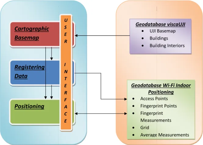
The system consists of fiv system is divided in two pa parts are related between figure. The figure is a gener
Figur
The geodatabase viscaUJI p a map of buildings and a cartographic subsystem) m provided by the ArcGIS SD visualize what it wants.
CLIENT PART
Cartographic
Basemap
Registering
Data
Positioning
esign centf five sub-systems as illustrated in the next figure o parts, the client part (a mobile device) and a serve en them and the subsystem inside the parts too, as neral scheme of the system.
Figure 15: General schema of the system designed
JI provide to the system the basemaps: two basema d a map with different layers, one per floor. The
) manage and organize these information usin SDK. This subsystem provides same tools to allow
ART
SERVER
Geodataba
• UJI B • Build • Build
Geodatabase
Positi
• Access Po • Fingerprin • Fingerprin Measurem • Grid • Average U S E R I N T E R F A C E 30 igure. The whole erver part. These , as shown in the
emaps of the UJI, The client, (the using the tools allow the user to
VER PART
tabase viscaUJI
JI Basemap uildings
uilding Interiors
Project Overview and Desig
There are two main functio Access Point or antenna an this function of register a f (perform the offline phase o Add fingerprint register fu phone. Then, when the use point the fingerprint data fingerprint measurement an points data in the fingerprin are in the server.
Add Access Point or antenn touch on the screen. The information of the antenna is. This information is includ appears and the user select the antenna that it want t viewing the antenna is add antenna.
The positioning subsystem The difference is that this f compares the current finge the most similar fingerprint
esign
nctions of the registering subsystem. The first one a and the other is registering a Wi-Fi fingerprint. At r a fingerprint is focused to add a fingerprint in the ase of the Indoor Positioning method).
r function uses the data of the Wi-Fi Manager o user touch on the mobile screen and the system re
ata and save in the Wi-Fi Indoor Geodatabase th nt and the floor that the user is displaying. This funct rprint points feature layer and the measurements in
tenna function add an antenna where the position The informatics department of the UJI campus nnas: name or code and building and floor where e cluded in the system and when the user touch the m elect the name of the antenna. Then the user select
nt to add. If this antenna is in the same floor tha added, but if not, the system don’t allow to the use
em use many of the methods of the add fingerprint his fingerprint is not added to the geodatabase. Th ingerprint with the geodatabase, and returns the p
rint previously registered in the offline phase.
ne is register an t. At the moment the geodatabase
er of the mobile m register at this e the point, the unction store the ts in a table that
ion that the user pus provided us ere each antenna the map, a dialog lect the name of that the user is user to add this
Project Overview and Desig
Joan Pere Avariento Vicent
9-.
MOBILE PLATF
The mobile platform sele different versions of their different versions of the observes the relative numbTable 3: Comparison betwee run
Higher versions of the plat improvements respect the one has to take into accou percentage of devices runn compatible with the previou Each version of the Androi this work the target versio Gingerbread. The API used 10.
In next table one can obse that can use the developed
Version 2.3.3
Table 4: Android platform ver esign
cent
LATFORM
selected to develop the application is Android. eir platform. There are same many active devices he Android platform. In the next graphic and ta
mber of devices compared with the version that are
ween the Android platform version respect the relative numbe running with this platform (Android developer)
platform has new tools and functionalities, and the the older versions. To select the target version of
ccount two main factors: the most recent as poss running with this versions. The higher versions ar evious.
droid platform has a specific API to develop the ap ersion selected to develop the application is the
sed to develop an application with this version is the
bserve the selected version and the relative numb ped application.
Codename API Distr
Gingerbread 10
version used and relative number of devices compatible with (31-1-2013)
32 id. Android has ices running with d table one can t are running.
mber of devices
d there are same of the platform possible and the s are completely
e applications. In he 2.3.3, named s the API number
umber of devices
Project Overview and Desig
10-. POSITIONING T
The method that perform t This technique is explained There are two phases in th developed performs correct To carry out the mapping fingerprints. Three points h average of these fingerprin performed using ArcGIS too in the server.esign
ING TECHNIQUE
rm the application developed is the Wi-Fi fingerprin ned in the chapter 5.3.
n this technique: offline phase and online phase. Th rrectly the first phase, the offline phase, called mapp ping phase, the application provides a function to
nts have been stored by each cell of the 3x3 met prints are calculated and assigned for each cell. This
tools and a new table of these averages are create
rprint technique.
. The application apping phase. n to register the
Project Overview and Desig
Joan Pere Avariento Vicent
11-. SERVER PART
The data used to visualize t on the campus. One of thes server) and the other one c Whoever that want to have net. There are two options VPN connection.In these servers there are i sharing GIS resources (m accessing trough Internet. query this information, app that the GIS resources are technology: the data is cen with the most up-to-date in The ArcGIS Server REST AP Web interface to services h by the REST API are access service published with ArcG The ArcGIS REST system i themselves (catalog, map, operation (exporting a map
esign
cent
ART
lize the UJI campus are in two servers. These server these servers contains all right data of the Smart Cam ne contains all testing data (MasterGeotec server). have access to these servers will have to be connect
ions to connect: directly connected to the UJI net
re installed ArcGIS Server. ArcGIS Server provides a (maps, feature layers...). One can access to th net. Depending the settings of the resources, one apply edits, delete,... The main advantages of use
are the same as sharing any data trough any ki centrally managed, supports multiple users and pr te information.
T API (Representational State Transfer), provides a es hosted by ArcGIS Server. All resources and operat
cessible through a hierarchy of endpoints or URLs ArcGIS Server (ESRI).
m is a hierarchy of resources. Some resources a ap, layer, etc.). Other resources are produced as a map results in a map image resource of an operation
34 rvers are located Campus (Geotec
nected to the UJI net or through a
es a platform for o this resources one can access, se a GIS server is y kind of server d provide clients
s a simple, open ations exposed RLs for each GIS
Project Overview and Desig
One can observe in the follo using the URL of the servers Geotec server: http://geote
Figu
MasterGeotec server : (in t http://mastergeotech.dlsi.uj
Figure 17: M
The resources used at the service. The map services a dynamic map and others as interaction between the la feature services are used to support the "Apply edits" geodatabase of this system
esign
following figures the interface of the REST API throu rvers used in this work:
eotec.dlsi.uji.es/arcgis/rest/services/UJI
Figure 16: Service directory of the Geotec server
(in this case the folder of this project) lsi.uji.es/arcgis/rest/services/WifiIndoor
: MasterGeotec server, inside the folder of this project
the mobile application are the feature services es are used to visualize information. In some cases rs as a tiled map. The dynamic map visualization offe
e labels of the map depending of the scale of visua ed to register the data using the mobile device. Fea
its" operation. Therefore this is the best way to tem.
hrough a browser
Project Overview and Desig
Joan Pere Avariento Vicent The following list show all d Services used that are in the
• UJI/Buildings (MapS • UJI/viscaUJI desatu • UJI/viscaUJI (MapSe
Services used that are in the • WifiIndoor/Antenna • WifiIndoor/WiFi Sca • WifiIndoor/Building • WifiIndoor/Grid (M Figure 18 a)
c)
esign
cent
all data used as a map in the application. n the Geotech server:
apServer)
saturado (MapServer) apServer)
n the MasterGeotech server: enna (FeatureServer)
i ScanPoints (FeatureServer) ldingInteriorbyFloor (MapServer)
(MapServer)
Figure 19: UJI Buildings interior by floor
18: a) UJIBuildings; b) viscaUJI desaturado; c) viscaUJI b)
Project Overview and Desig
The building interior by floo the original data contains a each floor has the attri BuildingInteriorbyFloor has light to use in a mobile devi The Antenna feature conta feature the information reg MAC. The WiFi ScanPoin Measurements. This featur ScanPoints layer have the in the device using the coordi Measurements layer is a measured in each point. T network, the MAC of the Ac The next table shows the fie
Feature Name Layer Antenna Antenn
Grid Grid
WiFi ScanPoints WiFi ScanP Measurem Averag Measur Table esign
floor map is based on the data of the viscaUJI geod ins all data of the building in the same layer but eac attribute floor that specifies the floor where
has different layers, one per floor. In this way the device.
ontains the Access Points and its geometry type is n registered is the Name of the Access Point, the F
Points feature contains two layers: WiFi Sca ature contains the data of the fingerprint database he information of the points: Floor, coordinates GPS ordinates provided by the network and the ID of ea s a table that contains the measurements of the t. The fields of this layer are: ID of the point, the e Access Point and the intensity received.
e fields of this features:
ayer Fields
tenna OBJECTID FLOOR NAME
rid OBJECTID FLOOR ID_CELL canPoints OBJECTID ID_POINT FLOOR X_G
rements OBJECTID ID_POINT FLOOR MA erage
asure. OBJECTID ID_CELL FLOOR MA le 5: Features fields of the WiFi Indoor Geodatabase
geodatabase, but t each element in re the data is. the data is more
e is point. In this he Floor and the ScanPoints and base. In the WiFi GPS provided by f each point. The the WiFi signals the name of the
MAC
X_GPS Y_GPS
MAC NAME INTENSITY
Project Overview and Desig
Joan Pere Avariento Vicent Next figure shows the Class
Figure esign
cent
lass Diagram of this Features.
igure 20: Diagram of the Geodatabase Architecture
Project Overview and Desig
12-. CLIENT PART
12.1. Software S
To develop the application dEclipse IDE for Java Android SDK ArcGIS SDK for And Eclipse is the software used ins (Android SDK and Arc necessary tools and librari whole ArcGIS functionality. The development of an An screens that comprise the contain images, buttons, te Activities.
An Activity is an applicatio interact in order to do som user interface. The window and float on top of other wi An application usually con other. Typically, one activity presented to the user when then start another activity i In the next figure there a between states.
esign
RT
are System Design
ion different tools are needed: ava DevelopersAndroid
used to develop the application. In this applications t ArcGIS SDK) have been installed. This two SDK braries to target the application to the Android p
lity.
Android application is carried out by developing th the application. Each screen is an interface becau s, text, etc. In Android, each of these interfaces a
cation component that provides a screen with whi something. Each activity is given a window in whic dow typically fills the screen, but may be smaller tha
r windows.
consists of multiple activities that are loosely bo tivity in an application is specified as the "main" acti hen launching the application for the first time. Eac ity in order to perform different actions.
re are represented the loops and the paths an
ons the two plug-SDK provide the
id platform with
ng the successive ecause it will be es are known as
which users can hich to draw its r than the screen
y bound to each activity, which is Each activity can
Project Overview and Desig
Joan Pere Avariento Vicent Figu
In the application develope and the indoorpositioning a The Use Case Diagram of th
esign
cent
Figure 21: Activity lifecycle (Android developer)
loped there are two activities implemented: the ing activity.
f the application is shown in next figure:
Figure 22:Use Case Diagram