Universidade de Aveiro Ano 2019
Departamento de Eletrónica, Telecomunicações e Informática
Filipe Cabral Amaral
Nunes da Costa
Aplicação SDN de controlo de banda para redes
OpenFlow
A bandwidth-aware SDN application for OpenFlow
enabled networks
Universidade de Aveiro Ano 2019
Departamento de Eletrónica, Telecomunicações e Informática
Filipe Cabral Amaral
Nunes da Costa
Aplicação SDN de controlo de banda para redes
OpenFlow
A bandwidth-aware SDN application for OpenFlow
enabled networks
Dissertação apresentada à Universidade de Aveiro para cumprimento dos requisitos necessários à obtenção do grau de Mestre em Engenharia de Computadores e Telemática, realizada sob a orientação científica do Doutor Pedro Alexandre de Sousa Gonçalves, Professor adjunto na Escola Superior de Tecnologia e Gestão de Águeda e do Doutor Daniel Nunes Corujo, Investigador Doutorado do Departamento de Eletrónica, Telecomunicações e Informática da Universidade de Aveiro.
o júri / the jury
presidente / president Professor Doutor Diogo Nuno Pereira Gomes
Professor Auxiliar do Departamento de Eletrónica, Telecomunicações e Informática da Universidade de Aveiro
vogais / examiners committee Doutor Sérgio Miguel Calafate de Figueiredo Engenheiro Sénior, Altran Portugal
Doutor Daniel Nunes Corujo
Doutorado (nível 2), Departamento de Eletrónica, Telecomunicações e Informática da Universidade de Aveiro
agradecimentos /
acknowledgments
A execução deste trabalho só foi possível devido à colaboração, disponibilidade e empenho de algumas pessoas, desde já, a todos o meu muito obrigado.
Aos professores, Pedro Gonçalves e Daniel Corujo pela orientação neste trabalho, por todo o conhecimento científico comigo partilhado, pela paciência que tiveram para comigo e pelo apoio que me deram.
Agradecer ao Engenheiro Luís Silva pelo apoio, disponibilidade e ajuda na programação e instalação da placa FPGA.
Quero agradecer especialmente à minha mãe, ao meu pai e à minha irmã por terem estado sempre ao meu lado em todos os momentos, por todo o incentivo e força que me deram ao longo destes anos. Obrigado!
palavras-chave
SDN, OpenFlow, Software Defined Networking, controlador SDN, Ryu.resumo
Software Defined Networking (SDN) é uma tecnologia de rede recente que melhora as tecnologias existentes, separando o plano de controlo do plano de dados. Altera a rede de forma a que esta seja mais dinâmica, menos complexa e mais fácil de interagir e automatizar que, por sua vez, pode levar ao desenvolvimento de software mais eficiente e eficaz. Apesar de ser uma tecnologia bastante recente, esta é compatível com os switches existentes e outros dispositivos de rede que tenham suporte para o protocolo OpenFlow. Nesta dissertação, é utilizado o controlador Ryu (um controlador SDN desenvolvido em Python) que em conjunto com o protocolo OpenFlow gerem o plano de dados.Neste trabalho foi implementado um mecanismo de controlo da rede sob a forma de uma aplicação para o controlador Ryu para controlar o tráfego de múltiplos sensores, tendo como principal exemplo uma rede dentro de um veículo. O mecanismo de gestão de recursos implementado visou garantir resultados de latência dos pacotes comutados na rede, tendo em conta o número variável de clientes a enviar tráfego na rede.
De acordo com os resultados obtidos, o tempo que um pacote demora a ir da sua origem até ao seu destino e de volta à origem varia entre 15 ms a 35 ms, quando os pacotes têm de ser tratados pelo controlador, e varia entre 0,5 ms e 1,8 ms, quando não passam por esse processo.
keywords
SDN, OpenFlow, Software Defined Networking, SDN controller, Ryu.abstract
Software Defined Networking (SDN) is a recent networking technology that improves existing technologies by separating the control plane from the data plane. It changes the network so that it is more dynamic, less complex and easier to interact with and to automate which, in turn, can lead to the development of more efficient and effective software. Despite being a fairly recent technology, it is compatible with existing switches and other network devices that support the OpenFlow protocol.In this dissertation, the Ryu controller is used (an SDN controller developed in Python) that together with the OpenFlow protocol manage the data plane. In this work, a network control mechanism was implemented in the form of an application for the Ryu controller to control the traffic of multiple sensors, the main example being a network within a vehicle. The implemented mechanism for resource management aimed at guaranteeing the latency results of the packets traveling across the network, taking into account the variable number of clients sending traffic on the network.
According to the results obtained, the time it takes for a packet to go from its source to its destination and back to the source varies between 15 ms and 35 ms when the packets have to be handled by the controller and varies between 0,5 ms and 1,8 ms, when they do not go through this process.
Index
Figure List ... iii
Table List ... v Acronyms ... vii 1. Introduction ... 1 1.1 Motivation ... 1 1.2 Goals ... 2 1.3 Methodology ... 2 1.4 Document Structure ... 3
2. State of Art & Background Technologies ... 5
2.1 Background ... 5
2.2 OpenFlow ... 7
2.3 Software Defined Networking ... 12
2.4 Controller... 15
2.4.1 Ryu ... 16
2.5 OpenFlow Virtual Switches ... 17
2.6 Technologies relevant to Automotive systems ... 18
2.7 Mininet ... 19
2.8 Zen Network ... 20
3. Concepts & Tools ... 21
3.1 Quality of Service ... 21
3.2 Real-time communication... 21
3.4 REST ... 22
4. Architecture ... 23
4.1 Operation Mode ... 29
5. Implementation ... 33
5.1 Initial Implementation ... 33
5.2 Limiting the Bandwidth ... 35
5.3 Flow Authorization & Administrator Application ... 36
5.4 Multiple Switch Topology ... 37
6. Evaluation ... 41
6.1 Meter Evaluation ... 41
6.2 Algorithm Evaluation ... 43
6.3 Travel Time when Processed by the Application ... 48
6.4 Evaluation without Bandwidth Restriction ... 49
6.5 Evaluation without Timeout ... 52
7. Conclusion ... 57 Appendix A ... 59 Appendix B ... 61 Appendix C ... 67 Appendix D ... 69 Glossary ... 71 Bibliography ... 73
Figure List
Figure 1 - OSI model and TCP/IP model with associated protocols, adapted from [15] and protocols adapted
from [16]. ... 6
Figure 2 - SDN architecture planes. ... 13
Figure 3 - OpenFlow switch packet handling, reproduced from [32]. ... 14
Figure 4 - Single switch, single host architecture. ... 24
Figure 5 – Single switch, multiple hosts architecture. ... 25
Figure 6 - Multiple switches architecture. ... 26
Figure 7 – Possible architecture of a SDN system... 27
Figure 8 - Signalling diagram of the messages exchanged between the application, the controller, a switch and hosts. ... 28
Figure 9 - Application Architecture. ... 29
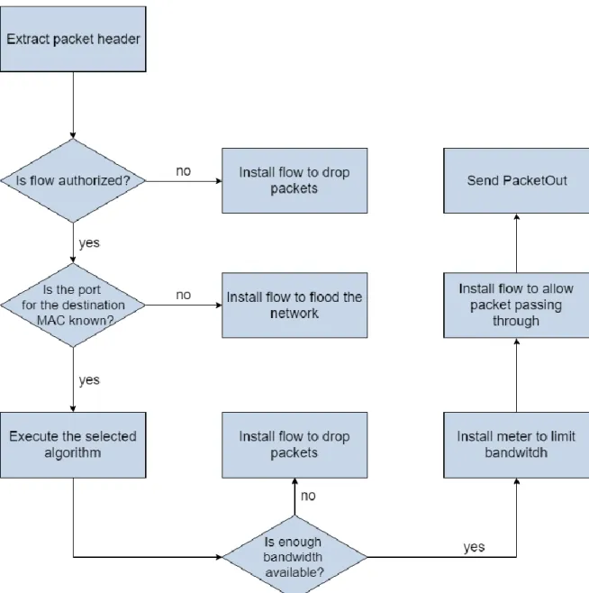
Figure 10 - PacketIn handling inside the application. ... 31
Figure 11 - Signalling diagram of the initial communication between the switch, the controller and the application. ... 33
Figure 12 - Workflow of the initial packet processing. ... 34
Figure 13 - Workflow of packet processing including meters. ... 35
Figure 14 – Workflow for packet authorization. ... 36
Figure 15 – Diagram about Mininet multiple switches, multiple hosts topology script, presented in Appendix C. ... 38
Figure 16 - Architecture with hosts split into left side and right side. ... 39
Figure 17 – Diagram about the Host script, presented in Appendix D. ... 40
Figure 18 - Setup for meter testing. ... 41
Figure 19 - Packets received from FPGA sending at around 30 Mbps. ... 42
Figure 20 - Packets received from FPGA sending at around 30 Mbps with a meter of 10 Mbps applied. ... 42
Figure 21 - Time between packet transmission and return for a given number of active hosts using ... 44
Figure 22 - Time between packet transmission and return for a given number of active hosts using ... 45
Figure 23 - Number of values corresponding to the time taken between packet transmission and return when installing a new flow for algorithm 1. ... 48
Figure 24 - Number of values corresponding to the time taken between packet transmission and return when
installing a new flow for algorithm 2. ... 49
Figure 25 - Time between packet transmission and return for a given number of active hosts using ... 50
Figure 26 - Time between packet transmission and return for a given number of active hosts using ... 51
Figure 27 - Time between packet transmission and return for a given number of active hosts using ... 53
Table List
Table 1 - OpenFlow 1.3 messages that are employed in this work. ... 8
Table 2 - OpenFlow 1.3 messages that are not employed in this work. ... 9
Table 3 – OpenFlow 1.3 message header structure. ... 12
Table 4 - Ryu custom OpenFlow events used in the development of this work. ... 16
Table 5 - Average and standard deviation of the time taken between packet transmission and return for a given number of active hosts using both algorithms. ... 46
Table 6 - Expected average minimum and maximum values, obtained from t-Student distribution with confidence of 95%. ... 47
Table 7 - Average and standard deviation of the time taken between packet transmission and return for a given number of active hosts using both algorithms, where the bandwidth control was turned off. ... 52
Table 8 - Average and standard deviation of the time taken between packet transmission and return for a given number of active hosts using both algorithms, where the timeouts were turned off. ... 55
Acronyms
AVB Audio/Video Bridging standard
CAN Controller Area Network
ECU Electronic Control Unit
FPGA Field-programmable gate array HTTP Hypertext Transfer Protocol
IEEE Institute of Electrical and Electronics Engineers
IP Internet Protocol
ISO International Organization for Standardization
JSON JavaScript Object Notation MAC Media Access Control
OSI Open Systems Interconnection
OSPF Open Shortest Path First OVS Open vSwitch
QoS Quality of Service
REST Representational State Transfer SDN Software Defined Networking
SNMP Simple Network Management Protocol TCP Transmission Control Protocol
TSN Time-Sensitive Networking
1. Introduction
The Internet is an important innovation that brought users together by allowing us to communicate with each other even if they are spread across the world, through a computer. Humanity, always wanting to modernize, started connecting more and more devices to this global network, ranging from tablets, smartphones, household appliances to sensors contained within electronic devices, vehicles and clothes. This became known as the Internet of Things [1], and it is a paradigm that has been established on the basis that all the appliances, electronic devices and sensors communicate with each other and with the user. These devices are always improving to become more efficient, in terms of power usage and processing power, more reliable and more adapted to each users preferences but, this also means that they require better and steadier connections where the flow of data must have enough bandwidth to travel, sometimes with low to no delays, through multiple nodes and links in the path between the source and the destination. Common networking is not designed to withstand such large amount of traffic [2].
1.1 Motivation
This work aims to analyse the impact of Software Defined Networking (SDN) [3] [4][5][6] in the systems that are part of smaller networks with special focus in those connecting all the devices and components inside a vehicle, comparing it to technologies such as Controller Area Network (CAN) [7] and FlexRay [8], which are traditionally used in the connection of those components.
In the past few years, the world has seen a very rapid growth in the amount of technology being put into vehicles, an increasingly larger number of cameras and infotainment applications which require a lot of bandwidth and sensors [9] used for road assistance. These transmit critical information that must be sent with very low delay to the vehicle main computer to guarantee the security and well-being of its passengers.
Another motivation is to contradict the fact that most of these networks are proprietary. As such, this work aims to manage a network by using only open-source software like the Ryu SDN controller, OpenFlow switches and Ethernet cables.
In this dissertation, the switches run an application layer protocol called OpenFlow [10], that gathers the characteristics of each switch making them available to devices that use the same protocol and allows the
management of flows that control how the packets travel inside the network. An SDN controller is an application that, together with the OpenFlow protocol, governs the network, creating and removing rules in each switch to block or allow the data packets to pass through while also limiting the bandwidth used. The application keeps information about each flow and each switch. This information is used to implement Quality of Service (QoS) methods and shortest path methods through the use of the third-party software library, Zen from Network Dynamics [11], an alternative to NetworkX [12], which allows the controller to have a notion of the topology of the network. These two are used together to direct the flows through the shortest paths where the switches have the most available bandwidth, resulting in less overloaded links and switches.
1.2 Goals
The goal of this thesis is to demonstrate that a SDN controller could be used together with network routing devices that support OpenFlow to connect the multiple electronic components inside smaller proprietary networks such as those in a vehicle, allowing the information to travel at speeds equal or better to those seen in the proprietary systems, while providing equal or better reliability.
1.3 Methodology
The work developed can be divided into multiple stages with an increasing amount of complexity and network devices changing the quantity of switches and hosts. The dissertation was developed using the Ryu SDN controller [13], OpenFlow version 1.3 and OpenFlow 1.3 Software Switch. The ambient for testing the first stage was composed of two computers and a Field-Programmable Gate Array (FPGA). The other two stages were tested inside a Mininet [14] virtual machine. There is more information about the software and hardware used in the section 6 and about the architecture in section 4.
In the first stage of the work, it was developed the setup for creating and removing flows, the setup for QoS rules and the management of resources and retrieval of information about the network and its devices.
The second stage introduced three different priorities for the QoS rules and the authorization of flows through either a file existing within the application directory or through another application, referred to as the administrator application, developed to communicate with the main application. The testing environment for this stage was a simulation of a simple network composed of only one switch and multiple hosts.
The final testing environment was a simulation of a network consisting of four switches, where two of them worked as redundant links between the other two and these last ones were connected to hosts. The application suffered a major overhaul as it had not been setup to work with multiple switches and to do the routing through a path required that the controller retrieved and maintained information about them. For this to be implemented the topology library Zen from Network Dynamics [11] was imported to the application. The
redundancy in the network is still necessary because SDN cannot solve hardware problems such as failure of a switch or link where this is the only point of communication between two other nodes.
Two algorithms were developed in this work to create paths for the packets to travel across the network from their source to their destination. On one algorithm, the packets stop at each switch where a message is sent to controller application which will either result in confirming or denying the passage of that packet and to those that correspond to the same source and destination. The other algorithm allows or blocks the passage in all switches at the same time of all similar packets, packets that contain the same source and destination. This setup in all switches occurs when a packet first arrives at any switch in the network and it is processed by the controller application. These algorithms are an improvement to the basic application, that is provided as an example with the Ryu controller, which only established connection with the switches and, when receiving a PacketIn, flooded the network to discover what was the port corresponding to its destination and installed a flow in the switch to allow the packets through to that destination.
1.4 Document Structure
Section 2 presents the two common network models comparing them to the SDN model, stating what improvements this last one brings in regards to the existing networks. This section also presents the state of art for the OpenFlow and SDN technologies, as well as, key technologies related to both.
Section 3 presents technologies, concepts and tools that were used throughout the development of this thesis.
Section 4 presents the architecture of the network used at the different stages in the development of this dissertation. In this section it is also presented the operation mode of the network.
Section 5 presents the implementation of the work.
Section 6 presents the results obtained and the evaluation of these results.
2. State of Art & Background Technologies
The Internet is a cluster of computer networks distributed across the entire planet that are interconnected, allowing users who connect to it to exchange data between them. This is possible because a common set of protocols are used for the exchange of data packets guaranteeing a medium of establishing the communication between the different computers and servers. Servers are special computers with great processing power and connections with higher speed and bandwidth, whose main functionality is to respond to requests from ordinary computers. These computers referenced here aren’t just laptop and desktop devices, but it is also referring to sensors, handheld devices and other devices which have processing power and are also connected to the Internet, this is what today is called Internet of Things. These devices can be anything ranging from smart televisions, home appliances, security sensors and cameras to cars and airplanes.
2.1 Background
One of the most well-known networking models is the Open Systems Interconnection model (OSI model) which is an International Organization for Standardization (ISO) standard for computer networks. Although this is only a conceptual model, its objective is to establish and guarantee connection between two computer systems in a local network, which is also called Ethernet. The computer networks in this model are split into 7 layers, the application layer is the upmost layer and corresponds to the applications that interact directly with the user and the services used by those applications. The sixth layer is the presentation layer, this layer converts data into a format that can be understood by the applications in the layer above. This layer also has a cryptographic function where the data can be encrypted, sent to lower layers and only decrypted in the sixth layer of the destination system. The fifth layer is the session layer and its goal is to control the sessions of the applications, allowing communication between multiple applications in separate systems. The transport layer is the fourth layer, its purpose is to control the data received from the session layer and segment it into packets that are sent through the lower layers. This layer is the bridge between the layers at the application level, 5 to 7, and the physical level layers, 1 to 3. The third layer is the Network layer, its goal is to route the packets and fragment them in the case that the packets are too large for one node and then unite them again in a following node. The data link layer is the second layer of the OSI model, it provides a way of transferring data between two nodes directly connected, can also detect errors in the physical layer and has an option to
try and correct those errors. The first layer is the physical layer, it defines the structure of the physical medium, sends and receives data from the physical medium by converting data to and from electrical and radio signals.
Figure 1 - OSI model and TCP/IP model with associated protocols, adapted from [15] and protocols adapted from [16].
Figure 1 compares both the OSI model and the Transmission Control Protocol/Internet Protocol (TCP/IP) model, by making a correspondence between the layers in each model. Although the protocols column is directly associated with the TCP/IP model, they can also be split between the OSI model layers that correspond to the same layer of the TCP/IP model. The application, presentation and session layers of the OSI model correspond to the application layer in the other model, the transport and network layers are the same in both models and the data link and physical layers of the OSI model correspond to the link layer of the TCP/IP model.
TCP/IP is one of the most important set of protocols for communication between devices in a network and a foundation of the Internet. TCP/IP is divided into 4 layers, the first layer being the link layer, it is the lowest layer, working right above the hardware, a header is given to the packets travelling in this layer and these are sent through the physical medium of a network. The next layer is named the Internet layer, packets in this layer carry an additional header on top that allows them to travel across networks. The transport layer is
responsible for establishing end-to-end channels where applications from higher layers don’t have to worry about how to route the messages through the lower layers, the transport connects lower and higher layers providing tools for controlling flows, avoiding and correcting errors, controlling the congestion of the network and segmenting the network into multiple subnetworks. Finally, the application layer, where most of the innovation occurs, it is the highest layer of the four, where the protocols and interfaces accommodated in it communicate directly with the hosts and other protocols.
The OpenFlow protocol [10], and therefore SDN [5], runs in the application layer of the TCP/IP model, above of the Transmission Control Protocol (TCP), and focuses on controlling flows of packets which can be found in the transport layer of the same model. The protocols used to implement Internet of Things communications also run in the application layer of the model.
Even though traditional IP network have been spreading everywhere they are still hard to manage [17], particularly when trying to implement high level policies where each device must be configured individually by the network technicians. Even worse is that traditional networks tend to be static [18] and as such dynamic configuration mechanisms are lacking or are literally non-existing. And the devices presented before as part of the Internet of Things are embedded with processing power that will only get better towards the future which generates elevated quantities of data [9] and can be very difficult to process in these traditional networks if there aren’t some improvements made to them.
Since each network vendor uses its own management technology, the hardware is tightly coupled with software, meaning that the networking devices are not easily programmable which, in turn, means that it is harder to innovate and improve the software and is also harder to automate these devices.
2.2 OpenFlow
In order to improve the way that experiments were done in production networks, the researchers at Stanford University introduced OpenFlow in 2008 [10] and, since 2011, this project has been standardized by the Open Network Foundation [19]. It was first proposed as way to improve research, however with its many advantages the aim of this project is to replace traditional networks in school and university campuses, datacenters and telecommunications.
The concepts of OpenFlow and SDN are interconnected and often referred to only as SDN. This occurs because OpenFlow is the most popular protocol used to establish the bridge between SDN and common networking devices, such as switches. OpenFlow is a protocol developed for the application layer, it can run in existing networking devices regardless of the brand as long as it has support for it. Through OpenFlow, the controller identifies the switches and their specifications, gathers statistics from the devices and applies rules that control the multiple flows of packets travelling in and out of the switches [20].
The OpenFlow protocol can be applied using a virtual switch, this is implemented in the application layer instead of the access layer, thus allowing compatibility with many switches. The two OpenFlow virtual
switch implementations used in this dissertation are Open vSwitch and OpenFlow 1.3 Software Switch, both of which will have a more detailed description in section 2.5.
For a switch to be an OpenFlow switch it must have at least these three components [10]: it must support the OpenFlow protocol, must contain a flow table and must have a secure channel to communicate with the controller. OpenFlow switches establish connection with controllers over a trust Transport-Layer Security (TLS) tunnel, from where the switches receive the rules and requests. TLS uses signed certificates to authenticate both users at each end of the tunnel as well as end-to-end data encryption. A flow table has multiple entries called flows, they contain information that is matched with arriving packets and, also, contain the actions that the switch must take after a packet is matched with a flow. Examples of actions are drop all packets, forward packets to a port or apply a limit to the bandwidth usage of a flow.
OpenFlow 1.3 was the version chosen for this work because it is by far, after version 1.0, the one that is most supported in terms of SDN controllers and other associated tools. A list of the available OpenFlow versions is presented in Appendix A and the improvements they bring to each previous version, the information is cited from the specification sheet version 1.5.1 [21], published by the OpenNetworking foundation [19].
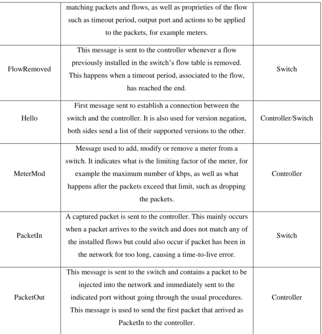
The messages available in OpenFlow 1.3 are shown in the following two tables, the first one contains the messages employed in this work. The second one contains other available messages that were not used either because they were not necessary for the basic communication of the work or their usage did not bring any additional contribution to this dissertation. Figure 8 in the section 4 is a signalling diagram that describes the usage of the messages presented in the first table.
Table 1 - OpenFlow 1.3 messages that are employed in this work.
Message Description Sent by
EchoReq
Message sent to check the connectivity between devices. If no response is received, the device assumes that it has been
disconnected from its pair.
Controller/Switch
EchoRes Response to the message EchoReq. Controller/Switch
Error
This message indicates that a problem has occurred when executing a command sent from the controller to the switch or
that there was a failure in the negotiations between the two.
Controller/Switch
FeatureReq Message sent to the switch to request a list of its features. Controller
FeatureRes Response to the message FeatureReq. Sent to the controller
and consists of the capabilities related to the switch and ports. Switch
FlowMod Message used to add, modify or remove a flow in a switch’s flows table. It contains the parameters to be used when
matching packets and flows, as well as proprieties of the flow such as timeout period, output port and actions to be applied
to the packets, for example meters.
FlowRemoved
This message is sent to the controller whenever a flow previously installed in the switch’s flow table is removed. This happens when a timeout period, associated to the flow,
has reached the end.
Switch
Hello
First message sent to establish a connection between the switch and the controller. It is also used for version negation, both sides send a list of their supported versions to the other.
Controller/Switch
MeterMod
Message used to add, modify or remove a meter from a switch. It indicates what is the limiting factor of the meter, for
example the maximum number of kbps, as well as what happens after the packets exceed that limit, such as dropping
the packets.
Controller
PacketIn
A captured packet is sent to the controller. This mainly occurs when a packet arrives to the switch and does not match any of the installed flows but could also occur if packet has been in
the network for too long, causing a time-to-live error.
Switch
PacketOut
This message is sent to the switch and contains a packet to be injected into the network and immediately sent to the indicated port without going through the usual procedures. This message is used to send the first packet that arrived as
PacketIn to the controller.
Controller
Table 2 - OpenFlow 1.3 messages that are not employed in this work.
Message Description Sent by
BarrierReq
Between this message and its response, all state modification messages create a synchronization point
between the controller and the switch.
Controller
BarrierRes Response for the message BarrierReq. Switch
Experimenter Proprietary message. Its structure is composed of a vendor
id and data designated by the user. Controller/Switch
messages it will send.
GetAsyncRes Response to the message GetAsyncReq. Switch
GetConfigReq Message sent to the switch to query about how the
fragmented packets are handled. Controller
GetConfigRes Response to the message GetConfigReq. Switch
GroupMod
This message modifies group tables inside the switch. Groups have actions that are applied to the packets posterior
to the actions in the FlowMod.
Controller
MultipartReq
This message is called StatsReq in older versions of OpenFlow and request information about each flow in the
switch.
Controller
MultipartRes Response to the message MultipartReq. Is called StatsReq
in older version of OpenFlow. Switch
PortMod Message used by the controller to modify the state of a
switch’s port. Controller PortStatus Asynchronous messages sent to the controller that indicate
a change of status in a switch’s port. Switch
QueueGetConfigReq Message to query about the state of a queue installed in a
port of a switch. Controller
QueueGetConfigRes Response to the message QueueGetConfigReq. Switch
RoleReq Message to modify the role of the controller among the
multiple controllers of a switch. Controller
RoleRes Response to the message RoleReq. Switch
SetAsync This message sets which asynchronous messages the
controller will send to the switch. Controller
SetConfig Message sent to the switch to define how it should handle
packets that are fragmented. Controller
TableMod
Message that indicates what happens to a packet when it does not match any flow in the table. The actions available are: send to the controller, send to another table or drop the
packet.
In OpenFlow, the switches just enforce the rules, all the decisions are made by the controller. When a new packet arrives that it does not recognize, a message, known as PacketIn, is sent to the controller with the information about the new packet. The controller then takes a decision and sends a reply, known as PacketOut, to the switch which in turn uses this information to take action on the initial packet by routing or dropping the packet.
One of the main messages that the controller can send is the FlowMod message which can insert, alter or remove a flow from the switch’s flow table. Having this table results in less packets being redirected to the controller, only packets that do not match any of the existing flows are redirected. Each flow table entry contains information on where to send the packets, how to match the packet with an entry, timeout to be applied, flow priority, flags and actions to apply, for instance, drop all packets related to the flow or limit the bandwidth used by applying a meter to the flow.
The matching of the packets with a flow is typically done by comparing both source and destination Media Access Control (MAC) addresses or IP addresses or other fields, such as, switch input and output ports. For instance, in this work, the most used matching parameters are the input port and the destination MAC address.
The OpenFlow protocol allows two different timeouts to be applied to each flow. An idle timeout will remove a flow from the switch if no packets travel through that flow during the time period defined by the timeout. A hard timeout will remove a flow from the switch after the timeout period has ended, even if packets are still using that flow to travel.
A meter is added as an entry to the switch’s table of meters through a MeterMod message (Appendix B) containing the meter id, a command to either add, modify or delete the meter. Meters are structures that apply bands to the flows in such a way that if the packets processed exceed the rate imposed by the band, they are dropped. The rate of the band can be defined by either bursts of packets, the number of kbps, number of packets per second or statistics.
Alongside meters, OpenFlow has queues that limit the packet egress rate when going out of a switch port, they are designed to ensure a certain packet flow rate, packets that exceed that rate are queued. This enables the deployment of QoS services with several available priorities to be defined for the flows. In versions of OpenFlow 1.0 and 1.1 only the guaranteed minimum rates are supported whereas from the version OpenFlow 1.2 onward the maximum rates are also supported.
The OpenFlow protocol has three modes of operation, a reactive mode, a proactive mode and an hybrid between the two [22]. In reactive mode, the virtual switch reacts to a packet arrival by searching in its own flow tables for flows that match the packet header and if no matches occur then it sends the packet information towards the controller so it can decide what to do, possibly resulting in an update to the flow table, this is the mode used in this work. In proactive mode, the flow tables are populated before the virtual switch is even started, the matching of packets occurs the same way as in reactive mode but if no matches occur the packet is discarded, so no PacketIn is sent to the controller. The hybrid mode combines the granularity of the proactive mode with the flexibility of the reactive mode.
Table 3 – OpenFlow 1.3 message header structure.
Field name Bits Description
Version 8 OpenFlow version used.
Type 8 Type of message.
Length 16 Length of the packet including this header.
Xid 32 Id associated with the packet. Used to facilitate replies to requests.
Table 3 represents the structure of the message header used by all the messages in OpenFlow. The header is always at the beginning of the message and contains four fields, the OpenFlow version used, the type of message, the total length of the packet including the header and an identifier associated with the packet.
The tables in Appendix B present the structures of the messages used in this dissertation, these structures correspond to OpenFlow version 1.3 [23] and only to the fields that appear after the header. More information on how these messages were used in the section 4. The hello message only contains the header, as such it does not have a dedicated table.
2.3 Software Defined Networking
OpenFlow is an instantiation of the SDN network paradigm. SDN [3] [4][5][6] is a networking technology that aims to separate the network’s “brain” from the data forwarding plane, where the packets flow. It can do this by having a centralized controller doing the management of the network and packet switching devices receiving orders from the controller. This allows each plane to evolve individually which brings a lot of new capabilities like flexibility, total control and notion of the network, allowing to solve many problems existing in the networks today [24]. These characteristics have increased the popularity and use of SDN in bigger infrastructures networks [25][26] and other technologies such as wireless [27][28] and cloud computing [29]. This also solves the problems of traditional networks by allowing the innovation in the software side without worrying about the hardware side. Through the use of a controller, the switches do not require the performance to run complex algorithms and more importantly, the fact that it allows for automation of the networking devices. However, SDN does still bring some scalability issues mainly due to the use of a centralized controller, these problems will be discussed in this later in this section.
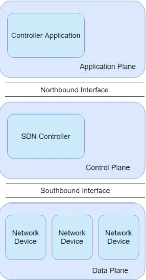
Figure 2 - SDN architecture planes.
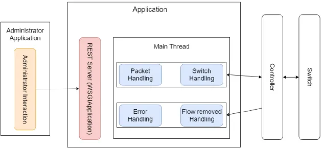
The SDN architecture (Figure 2) is composed of two main planes and an additional plane whose existence depends on the controller implementation. The lowest plane, called data plane, is represented by the forwarding devices that communicate inside the network and within networks, i.e., switches and routers that redirect the traffic, hosts that communicate with each other and other devices. The control plane containing the controller(s) which communicates with the switches to retrieve information and implement flows and rules to be applied to these flows, this plane is connected to the data plane through the southbound interface that transmits information between both. The additional plane is the application plane which runs above the controller plane and is connected to it through the northbound interface. It contains the main application which is the true “brain” of the network keeping information about the state of the network devices, implementing flows and running algorithms that control the network and decide which path a flow should take, sending the decisions taken as messages to the controller which are then communicated by the controller to the switches. The northbound interface is an API with instructions to help in the development of applications.
Some limitations to the scalability of SDN networks [24] are similar to those existing in traditional networks such as the switch must be able to receive a large number of packets, especially for networks where packets
come in bursts, as well as a failure in a link or switch that is the only communication point between two other nodes in the network, this can be solved by adding redundancy to the network. However, it does eliminate some limitations such as maintaining the state of the network across its devices and having to do the discovery of the network’s topology.
Limitations specific to SDN networks are:
• The processing speed of the controller [24], especially when there is only one centralized controller in the entire network. A controller receives a large quantity of packets that must be analysed, processed and, most of the times, an order must be given to the switches afterwards. One way to mitigate these problems is to add some parallelism in the CPU processing by using a controller that supports multiple threads [20] [30] [31]. Another way is by having distributed controllers, where each one has their own subnetwork or by having multiple controllers in the same network which could require some synchronization between them, for example to maintain the network topology equal between all the controllers.
• The switches must have enough space in their tables to keep all the information sent by the controller [24]. One way to avoid having to upgrade a switch or its memory capacity is by having the controller set up aggregated rules instead of having multiple rules for each flow stored in the tables.
• The failure of the centralized controller [24]. This could be solved by using multiple controllers that are synchronized and share the same state.
A basic SDN network contains multiple switches connected to a controller. When first booting up, the switches let the controller know that they are active by sending an Hello message, then the controller sets up a communication channel with each switch for future communications.
Figure 3 - OpenFlow switch packet handling, reproduced from [32].
Figure 3 presents the cycle of steps that an OpenFlow switch follows when handling a packet. When a packet arrives at the switch, the switch verifies the packet header against the existing flows previously set up, this is usually done by comparing the source and destination fields of the packet, other parameters are available for comparison. If the packet matches a flow, then the actions defined for the flow are applied to it, for example,
sending it to the assigned output port. In the case where the packet header does not match any flow, the switch sends a PacketIn message to the controller with that packet attached.
When the controller receives the PacketIn message, its information is processed by either the controller itself or it is passed on to the application running on the northbound bridge. After processing and saving the information to internal variables, the controller should send a FlowMod message to the switch, so that it installs a new flow in its table with an associated action. The main actions that can be applied are to route packets through a port, drop all packets, modify the header of the packets, add tags to the packets or apply a mechanism that limits the amount of bandwidth used by the packets corresponding to that flow. If the packets are to be accepted, the controller will also send a PacketOut message that contains the packet obtained from the PacketIn message, telling the switch to route that packet to the output port without going through the flow matching verification.
Flows can also be removed from switches, this mainly occurs due to timeouts set when installing a flow, and when that happens the switch sends a FlowRemoved message to the controller, letting it know that the flow is no longer active. For this to happen, the application had to activate the flag SendFlowRem in all the FlowMod messages that insert flows to the flow table.
2.4 Controller
A controller is a software that manages a SDN Network, it implements rules in the southbound components (switches and routers) and communicates with northbound components (applications) to decide what to do based on data coming from the switches and routers.
The SDN controllers’ scene could be compared to the early days of the computer operating system scene where each electronics shop, and even individuals, created their own operating system. There are a lot of SDN controllers [20] [26] [30], the following list has some of the most popular, all these controllers were developed with support for OpenFlow.
• Beacon – Java-based open source multi-threaded controller [33] developed in the Stanford University. Supports OpenFlow version 1.0;
• Floodlight – Java-based open source multi-threaded controller [34] developed by Big Switch Networks, it was part of the OpenDaylight project but due to conflicts with Cisco they were split. Supports OpenFlow 1.0 and 1.3 and has partial support for OpenFlow versions 1.1, 1.2 and 1.4 [35]; • Maestro – Java-based multi-threaded controller [36] developed in Rice University. Supports
OpenFlow version 1.0;
• NOX – C++-based open source multi-threaded controller [37] developed by Nicira Networks, now owned by VMware. It was developed alongside with OpenFlow and was the first OpenFlow controller. Supports OpenFlow version 1.0;
• OpenDaylight – Java-based open source controller [38] developed by the Linux foundation. Supports OpenFlow versions 1.0 and 1.3;
• OpenMUL – C-based open source multi-threaded controller [39] that focuses mainly in high performance flow handling. Supports OpenFlow versions 1.0, 1.3 and 1.4;
• POX – Python-based open source single-threaded controller [40] that branched from NOX. Supports OpenFlow version 1.0;
• Ryu – Python-based open source single-threaded controller [13]. It is designed to make managing and adapting network traffic easier and more agile. Supports OpenFlow versions 1.0, 1.2, 1.3, 1.4 and 1.5.
Ryu was the one chosen for this dissertation, although not the greatest for large networks such as those in warehouses, it has a pretty good performance when it comes to small networks [20] [30], like the one this work was designed to simulate. The reasons for choosing Ryu were its performance, the language in which it was developed (Python), the documentation available for it, as well as the fact that it is still being actively updated.
2.4.1 Ryu
The Ryu platform [41] establishes communication between the controller plane and the application plane through messages called events. Events are asynchronous and, when sent to an application, are stored in a FIFO queue until they are processed by the application thread.
Events are provided by Ryu for the case of the topology events, but Ryu also provides other events that it converts automatically from OpenFlow messages. This is done in the Ryu’s OpenFlow controller in which it decodes the message from the switch and send an event corresponding to the message to the application running in the northbound bridge of Ryu.
Ryu applications can register their interest in a certain event by using a decorator together with an handler method. Decorators extend the function of the handler method by informing the application that when the event specified in the decorator occurs, it should be processed by that method. In the case of the Ryu application, the events are the messages.
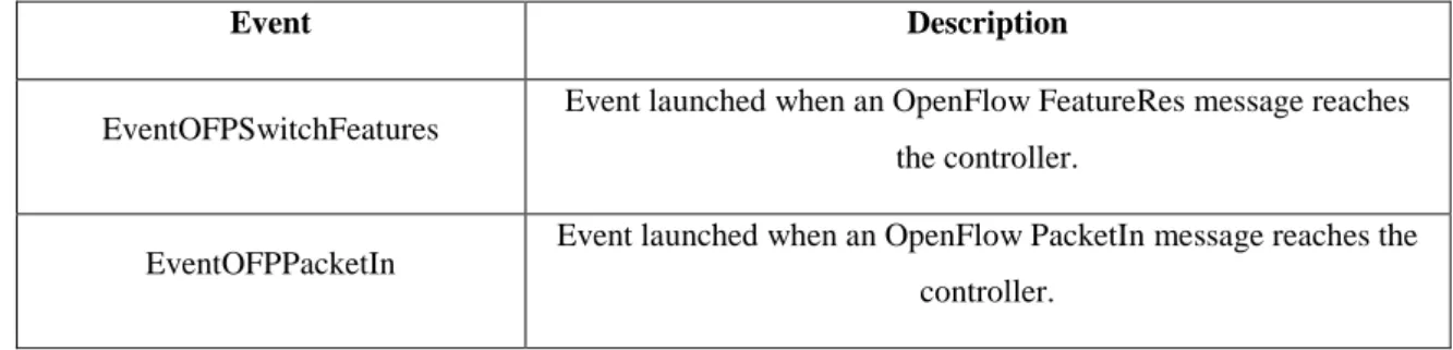
The following table contains the events used and handled in the development of this application.
Table 4 - Ryu custom OpenFlow events used in the development of this work.
Event Description
EventOFPSwitchFeatures Event launched when an OpenFlow FeatureRes message reaches the controller.
EventOFPPacketIn Event launched when an OpenFlow PacketIn message reaches the controller.
EventOFPFlowRemoved Event launched when an OpenFlow FlowRemoved message reaches the controller.
EventOFPPortDescStatsReply
Event launched when Ryu OFPPortDescStatsReply message reaches the controller. This is a response to the message OFPPortDescStatsRequest sent from the controller to the switch
and obtains information about each port of a switch.
EventOFPErrorMessage Event launched when an OpenFlow Error message reaches the controller.
EventSwitchEnter Ryu topology event. It is triggered when a new switch establishes connection with the controller.
2.5 OpenFlow Virtual Switches
Open vSwitch [42], also known as OVS, now owned by VMWare, was initially created by the team at Nicira with the purpose of being an open source virtual switch with many features only found on proprietary implementations at the time. It is now very important in the SDN environment being used in a large number of SDN deployments. One of the reasons being that it has no native SDN controller, unlike commercial solutions, which allows the use of any third-party controllers allowing to use the one fitting them the best or even develop their own.
OVS was the first OpenFlow based switching protocol used in this work. It worked fine for network pathing, when the virtual switch communicates with other devices in the network, and for packet redirecting, when the switch forwards or stops packets from crossing the network. When it was necessary to limit the bandwidth used by the flows it had some problems. The two methods of controlling bandwidth in OpenFlow are queues and meters, when using queues, it was not possible to limit the amount of bandwidth that each flow was using. With that, some research was done on meters and, it was concluded, that OVS did not support meters for the version corresponding to OpenFlow 1.3. With this in mind, it was necessary to try an alternative virtual switch.
OpenFlow 1.3 Software Switch [43], also known as ofsoftswitch13 or ofsoftswitch, is based on the Ericsson TrafficLab 1.1 softswitch implementation [44] updated to support OpenFlow 1.3. Uses the NetBee library [45] for packet parsing. Like OVS, it is also a popular open source virtual switch which allows the use of any third-party controller. A notice in the official github page [43] of this project informs its users that the switch will probably not have a lot of updates because its authors don’t have the time to be more dedicated to it.
The ofsoftswitch was the alternative OpenFlow based switching protocol used in this dissertation, after the problems had when trying to limit bandwidth in OVS. With this switch, queues were a problem as well because in order to be able to implement queues in ofsoftswitch it required the switch to be executed, in the command line, without the option “no-slicing” which resulted in an error as the software did not allow slicing
to be enabled in the ethernet ports. The term slicing [21] refers to the capability of splitting the amount of network bandwidth available between each queue. This technique was not used in this work. Instead, meters were used in ofsoftswitch which gave the best results, some of which are shown in the section 6.
2.6 Technologies relevant to Automotive systems
CAN [7] networks are based on real-time applications and allow the communication between microcontrollers and smaller devices, such as sensors, without the need for a more powerful computer to establish the exchange and to collect the information transmitted. As they are based on real-time applications, the medium used to transmit information must be fast and reliable, it must send and receive the messages even if a link failure occurs. The error control mechanism is an important feature of CAN networks, as it is done directly in the device where the error occurs. The CAN protocol defines a recessive bit that is used to know if a message is to be prioritized, when the bit is active, or not. When a device fails, error messages are broadcast into the network, if two messages are sent into the network, the device sending the one with less priority ceases their transmission, so that these messages do not occupy the bandwidth available. These will then be retransmitted by the central controller.
FlexRay [8], developed in 2000 by the FlexRay Consortium, is communication protocol for vehicles based on the CAN protocol. It uses multiple Electronic Control Units (ECUs) which communicate through a bus, but only one sends information at any given time. The communication channels used defined by FlexRay can have single or dual channels. An ECU only has permission to send messages in a slot of time defined by the MAC. The MAC is also used as an interface between an ECU and the Coding and Decoding (CODEC) block. When an ECU sends a message, the MAC verifies if it was sent inside the correct time slot if so, the message is forwarded to the CODEC which then encodes it and sends it to the communication bus. These slots are what allow the bandwidth of the network to be available when necessary.
The CAN bus is limited to a maximum of 500 Kbps [46] which is a bottleneck when considering the vast amount of bandwidth required by the very rapid growth in the amount of technology being put into vehicles [9]. In the same way, FlexRay being limited to 10 Mbps [46] can also be a bottleneck.
To counter these bottlenecks new technologies are being developed such as the Institute of Electrical and Electronics Engineers (IEEE) 802.1 Audio/Video Bridging (AVB) standard [47]. AVB is a set of standards whose objective is to provide streaming services that are time-synchronized and guarantee low latency.
The set is composed of the following standards:
• IEEE 802.1AS-2011 [48] – “Timing and synchronization for time-sensitive applications in bridged local area networks”;
• IEEE 802.1BA-2011 [47] – “Audio video bridging systems”; • IEEE 802.1Qat-2010 [49] – “Stream reservation protocol (SRP)”;
IEEE 802.1AS guarantees a precise synchronization of the time to all clocks, contained in the network's nodes. IEEE 802.1BA establishes profiles to build the networks that are used to transport time-sensitive audio/video data streams. IEEE 802.1Qat allows the establishment of resource reservations between the source and destination of a message, these resources correspond to switch buffers, such as queues. Two classes are defined by this standard that guarantee maximum latency up to seven hops from the original node, class A with a maximum of 2 ms and class B with a maximum of 50 ms. IEEE 802.1Qav guarantees a higher priority for time-sensitive traffic separating it from the non-time-sensitive traffic.
The Time-Sensitive Networking (TSN) IEEE 802.1 task group continued the work of the AVB task group. TSN [51] is a set of standards that extends AVB, in order to address high availability and very low latency transmissions. TSN adds time scheduling mechanisms to ensure the delivery of higher priority messages such as those with hard and soft real-time characteristics (see section 3.2). Other new feature is frame preemption where non-time-critical frames are suspended to allow the transmission of more time-critical frames. These new features enhance the protocol in order to guarantee latency low enough to support real-time transmissions.
When comparing SDN to TSN and according to [52], TSN provides standards and services that were tailor-made to fit the specifications of real-time applications. On the other hand, SDN follows a different path by introducing a programmatic centralized controller which brings remarkable flexibility to the networking systems. SDN is not custom-made for real-time applications and as such performs worse than TSN, but due to its flexibility, the development of SDN applications that are better at providing services for real-time systems is highly possible.
2.7 Mininet
Mininet [14] is a virtual machine system that simulates networks allowing investigators and developers to prototype large networks on a single machine instead of using an entire network of switches and routers [53] [54]. It enables the users to create custom network topologies, configure switches and hosts which are created as processes inside Mininet. Switches and hosts run their own operating system and have their unique ports, network interfaces and addresses. Mininet aims to simulate real-world networking by keeping the same packet delivery methods as hardware switches.
Hosts can run application code or specific network commands, like ping or ifconfig, and each host can run its unique operation. Alternatively, the user can start the network with the topology he chose and run a script afterwards that can interact with the entire network and its devices, enabling topology changes, running commands and obtaining information about the network or the devices in it.
Mininet establishes a connection between its switches and hosts with its own simulated controller or an external controller helping investigators and developers working on SDN controllers by making their work easier as many hardware networks still don’t support OpenFlow and those that do, cannot be used for
investigation because they are being used by other investigators in the same institution and don’t want their connection to the Internet to be blocked if some error occurs.
In this work Mininet is used to simulate networks composed of switches and hosts to develop and test the main application and the administrator application.
2.8 Zen Network
Zen [11], from Network Dynamics, is a Python library that allows the creation and manipulation of complex networks and subsequently the study of their topology and the dynamic of the network.
In this work, Zen is used to recreate the topology of the network inside the main application and, with that, calculate the shortest path through Dijkstra’s algorithm either with or without weights in each link. The weights of the networks are the amount of bandwidth already in use, in Mbps, in each link. It was an alternative to NetworkX [12] because this library was not compatible with the Ryu controller. Similar to Zen, NetworkX is a Python library that is used to know the topology of the network.
3. Concepts & Tools
This section presents some concepts, like Quality of Service and Real-time, and some tools, such as Wireshark and Representation State Transfer services, which are considered important for the development of this dissertation.
3.1 Quality of Service
Quality of Service, or QoS for short, are methods that measure and control the performance of services mainly used in computer networking, cloud computing and telephony. They make sure that a service has more or less quality depending on the priority attached to it. Quality can be measured by multiple aspects such as packet loss, throughput, transmission delay, availability, etc. [55]
• Packet loss is defined as the quantity or percentage of packets transmitted from the source that did not arrive its destination.
• Throughput is the maximum number of packets that can be transported across the network.
• Transmission delay or latency is the time it takes packets to travel from their source to their destination.
• Availability is the ratio between the time that the system is ready and available to transmit packets versus the total amount of time that the system has been running for.
In this work the main classifiers for the quality of service are the number of lost packets and the delay in the transmission of packets across the network.
3.2 Real-time communication
The concept of real-time was introduced in computing when the transmission of information must occur within a specified interval of time that begins when the information leaves the sender and ends when the destination device receives that information. These time constraints usually require the lowest latency possible, in order of the milliseconds and even microseconds, and have the top priority when QoS methods are implemented.
Finally, there are two definitions of real-time, the most commonly used when referring to real-time is named hard real-time and represents when all information must arrive within the time constraints without losses. The other definition is soft real-time which is used when a part of the information can fail some deadlines, but if a big part of the information arrives late the performance of the system will degrade.
In this work when real-time is mentioned, it refers to hard real-time for which the packets must travel within the lowest interval of time possible between the source and destination with top priority for QoS methods.
3.3 Wireshark
Wireshark [56] is a tool for analysing packets passing through specific interfaces which it is set to listen to. Wireshark is very useful for troubleshooting network communication problems and is commonly used as a packet analysis tool.
In this work this tool was mainly used for collecting data on the quantity of packets arriving to and leaving the controller and for verifying the effectiveness of bandwidth limiting methods, i.e., OpenFlow meters.
3.4 REST
Representational State Transfer (REST) are web services that follow a REST architecture style [57] and they offer interoperability between computer systems connected to the Internet. These systems are divided into two groups which are the servers and the hosts. This last group can ask for files/information stored in servers through a GET command or post files/information through PUT or POST commands. Another common command in this architecture is the DELETE command allowing hosts to remove files/information from the server. The server defines which commands are available for their hosts and can even define categories of users that have different permissions meaning they have access to different commands. REST architecture is defined by properties and restrictions based on the Hypertext Transfer Protocol (HTTP).
REST services are used to establish a connection between the main application and the administrator application where this last one sends a PUT command to the server running in parallel inside the main application, which communicates the result of the command to this last one.
4. Architecture
The architecture of SDN can contain two planes with an additional plane in some implementations, as it was already presented in the section 2.3. In this dissertation the controller plane is composed of only one controller, the data plane is composed of several switches and computers, which were called hosts. Finally, the application plane contains the application which will oversee and control the network infrastructure.
The switches receive information about the flows of packets from the controller and apply them to the packets that travel through the switch either blocking the packets or sending the packets via the output port which corresponds to the path towards their destination. The selected virtual switch was ofsoftswitch, the reasons for why it was chosen are explained in the section 2.5.
The controller is the brain of the system and makes the bridge between the application and switch. Ryu was the controller chosen because it is a Python-based controller, is still being updated and has support for multiple versions of OpenFlow mainly 1.3 which was the version used in this work.
Figure 4 - Single switch, single host architecture.
The initial architecture was composed of one computer which contained the four components presented in Figure 4. It was used to implement and test the basic functions of the application such as creating flows, blocking packets, allowing the traffic to pass through the network and applying methods to limit the bandwidth usage.
Afterwards the testing environment was changed to one simulated inside Mininet as it allows to scale up the number of switches and hosts in an easier and quicker way than gathering up more physical devices and switches.
This new architecture (Figure 5) was composed of multiple hosts, four hosts was mostly the number used, and only one switch which connected all the hosts with their unique switch port.
Figure 5 – Single switch, multiple hosts architecture.
With this architecture a new application was developed, which was named and referred to as the administrator application, it has the purpose of sending information about the flows of packets that should be authorized by the main application. This application is to be run on a separate computer from the one containing the SDN infrastructure and communicates with the controller application through REST commands.
For this to happen, a new thread was implemented in the controller application which runs separately from the main thread and contains a REST server that waits for new commands to be sent.
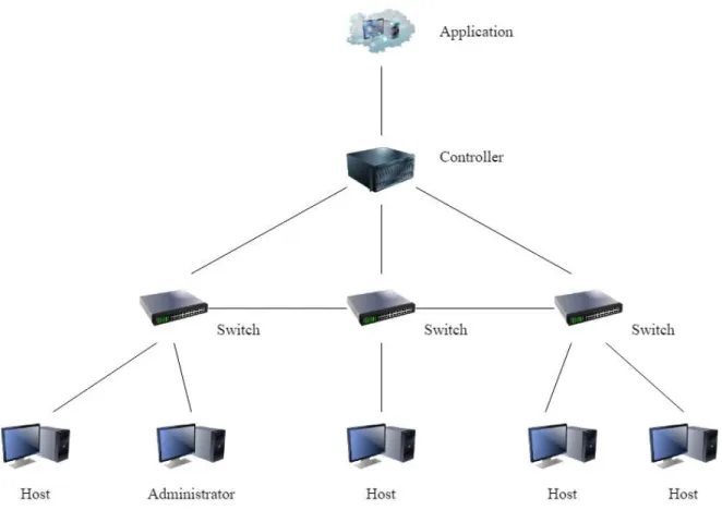
The final architecture contains four switches, two of those are on the edges and two are in the middle, and a variable number of hosts. The two in the middle are redundant and the two on the edges are the ones that establish the link with the hosts. The number of hosts is increased for testing purposes
Figure 6 - Multiple switches architecture.
With this architecture the application was altered to work with multiple switches, as well as implementing methods for establishing paths that install flows across multiple switches.
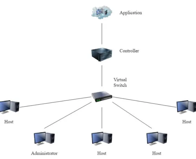
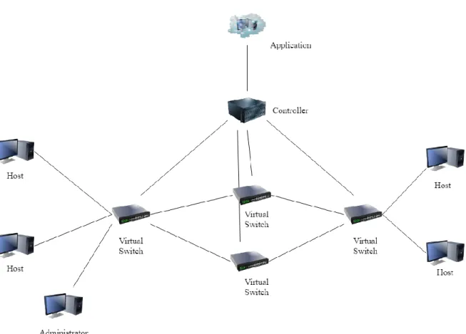
These three architectures were the ones used in this work, but other architectures could be used and tested, for example Figure 7, as long as they contain only one controller because the application is not prepared to work with multiple controllers.
Figure 7 – Possible architecture of a SDN system.
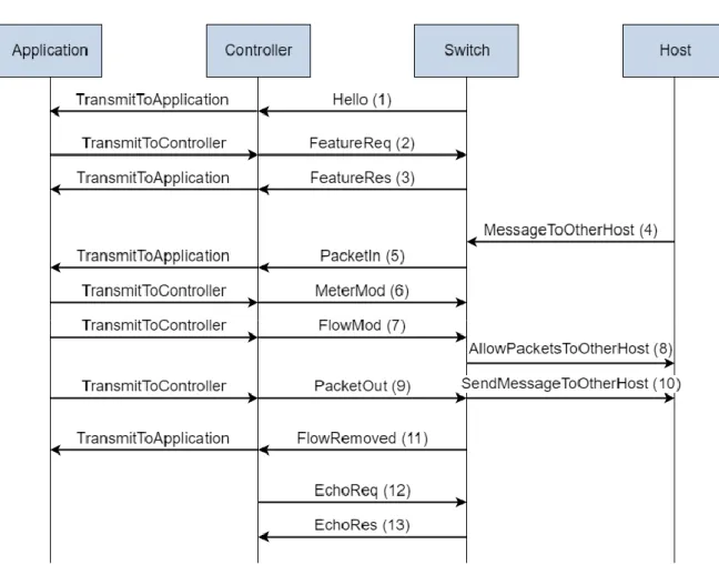
Figure 8 is a signalling diagram representing the messages exchanged between the application and the controller, the controller and a switch and between a switch and an host. The messages here presented between the controller and the switch are the only ones used in this dissertation which have been described in section 2.2 together with other messages also available in OpenFlow version 1.3. The messages exchanged between the switch and a host are fictional messages to represent the interaction between the switch and the host and will be described below. The messages exchanged between the application and the controller are fictional messages, the controller only exchanges the EchoReq (12) and EchoRes (13) messages, the others are always transmitted to the application and their responses are transmitted back to the controller.
The messages exchanged can be divided into three scenarios where they always occur:
• When a new switch connects to the network, the messages exchanged are Hello (1), FeatureReq (2) and FeatureRes (3) and respective “TransmitToApplication” and “TransmitToController” messages;
• Whenever a switch is connected to the controller, the messages exchanged are EchoReq (12) and EchoRes (13);
• The other messages are exchanged whenever a packet that does not match any flow in a flow table arrives at a switch.
Figure 8 - Signalling diagram of the messages exchanged between the application, the controller, a switch and hosts.
The first three messages represent the initial communication between the application and a switch, the Hello (1) message indicating that the switch wants to establish communication with the controller and the application, the FeatureReq (2) message where the application asks for the specifications of the switch and the FeatureRes (3) message which is the response to the previous message.
The following messages correspond to the normal communication between a switch and a host which also corresponds to the most important part of the application. A host sends a message to another host (MessageToOtherHost (4)), the switch receives that message and sends a PacketIn (5) to the application, the application processes that message, installs a meter through a MeterMod (6) and a flow through a FlowMod (7) with the associated meter. With the flow installed the packets sent by the host are allowed to pass through the port of the switch connected to the destination host (AllowPacketsToOtherHosts (8)) and the PacketOut (9) message is sent to the switch with the original packet that is then sent through the output port to the destination host (SendMessageToOtherHost (10)).
After the timeout, a flow is removed from the switch and the switch alerts the application with the FlowRemoved (11) message.
![Figure 1 - OSI model and TCP/IP model with associated protocols, adapted from [15] and protocols adapted from [16]](https://thumb-eu.123doks.com/thumbv2/123dok_br/15852172.1085729/26.892.174.737.204.715/figure-model-model-associated-protocols-adapted-protocols-adapted.webp)