Departamento de Inform´atica
Marcelo Jos´e Rodrigues Gonc¸alves
Model-based Testing of
User Interfaces
Universidade do Minho
Escola de Engenharia
Departamento de Inform´atica
Marcelo Jos´e Rodrigues Gonc¸alves
Model-based Testing of
User Interfaces
Master dissertation
Master Degree in Computer Science
Dissertation supervised by
Jos ´e Creissac Campos
Camille Fayollas
Acknowledgements
I would like to thank my advisers, Professor Jos´
e Creissac Campos and Camille Fayollas, for the
opportunity, support and suggestions given during the development of this dissertation. Thanks
for the support provided by the Research Grant level B1-D, with reference 6049/BI B1D/17.
Special thanks to my parents, my brothers and my friends for all the encouragement and
unconditional support.
Finally, to all those who were present during my academic formation, thank you.
The Graphical User Interface (GUI) is crucial for the success of an interactive system. Incorrect
operation of the GUI may inhibit the proper functioning of the system. Ensuring the quality of a
system is essential to its success. A practical way to ensure it is through software testing.
Model-Based Testing (MBT) is a black-box technique that compares the behaviour of the system under
test against the behaviour of an oracle (the system’s model). These tests are intended to verify
that the implementation of a software meets its specification.
Applying MBT tools to GUIs enables the systematic testing of the system by automatically
simulating user actions on the user interface. However, applying the MBT process to GUIs creates
several challenges such as the mapping between the actions in the model and the actions in the
application interface. This dissertation will focus on the model-based testing of graphical user
interfaces. The main objective is to further the development of the TOM Framework. The TOM
Framework supports the process of MBT applied to GUIs, in particular, web-based GUIs, enabling
the creation and execution of user interfaces tests and thus increasing the probability of error
detection in the tested interfaces.
Resumo
A interface gr´
afica do utilizador ´
e imprescind´ıvel para o sucesso de um sistema interativo. O
incorreto funcionamento da interface gr´
afica pode inibir o bom funcionamento da aplica¸
c˜
ao e,
consequentemente, do sistema de software. Assegurar a qualidade de um sistema ´
e essencial para
o seu sucesso. Uma maneira pr´
atica de o garantir ´
e atrav´
es dos testes de software. Os testes
baseados em modelos s˜
ao uma t´
ecnica de caixa-preta que compara o comportamento do sistema
sob teste com o comportamento de um or´
aculo (o modelo do sistema). Estes testes destinam-se
a verificar se a implementa¸
c˜
ao do software cumpre as suas especifica¸
c˜
oes.
A aplica¸
c˜
ao de ferramentas que suportem testes baseados em modelos em interfaces gr´
aficas do
utilizador permite o teste sistem´
atico do sistema, simulando automaticamente a¸c˜
oes realizadas pelo
utilizador na interface disponibilizada. No entanto, a aplica¸
c˜
ao do processo dos testes baseados
em modelos em interfaces gr´
aficas cria v´
arios desafios, como por exemplo, o mapeamento entre
as a¸c˜
oes no modelo e as a¸
c˜
oes na interface da aplica¸
c˜
ao. Esta disserta¸c˜
ao incidir´
a sobre os testes
baseados em modelos e a sua aplica¸
c˜
ao a interfaces gr´
aficas do utilizador. O principal objectivo
´
e continuar o desenvolvimento da Framework TOM. A Framework TOM suporta a aplica¸
c˜
ao do
processo de testes baseados em modelos a interfaces gr´
aficas do utilizador, permitindo a cria¸
c˜
ao e
execu¸c˜
ao de testes em interfaces e aumentando a probabilidade de detec¸c˜
ao de erros nas interfaces
testadas.
1
i n t r o d u c t i o n
1
1
.1
Motivation
2
1
.2
Main Goals
3
1
.3
Document Organization
3
2
s o f t wa r e t e s t i n g
4
2
.1
Basic Definitions
5
2
.1.1
Verification and Validation
5
2
.2
Testing Methods
6
2
.2.1
White Box Testing
6
2
.2.2
Black Box Testing
6
2
.2.3
A Comparison of Testing Methods
7
2
.3
GUI testing
7
2
.3.1
Manual GUI testing
7
2
.3.2
Automated GUI testing
8
2
.4
Model-Based Testing
10
2
.4.1
The process
11
2
.4.2
Model-Based Testing of User Interfaces
12
2
.5
Summary
16
3
t o m g e n e r at o r
17
3
.1
Generation process
17
3
.1.1
Modelling the user interface
19
3
.2
Type of generated tests
22
3
.2.1
Web Applications
22
3
.2.2
IRIT Scenarios
25
3
.2.3
Json
28
3
.3
Summary
30
4
c o n t r i b u t i o n s
31
4
.1
Code Refactoring
31
4
.1.1
Patterns Used
32
4
.2
Web Services layer
34
4
.2.1
Packages
35
4
.2.2
Database
37
4
.2.3
Achieved Behaviour
39
Contents v
4
.3
TOM App
42
4
.3.1
Architecture
42
4
.3.2
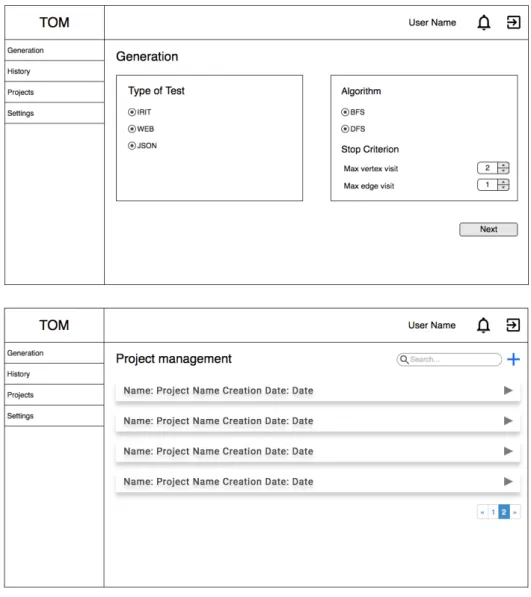
Mockups
43
4
.3.3
Technologies used
44
4
.3.4
Functionalities
46
4
.4
Summary
51
5
c a s e s t u d i e s
52
5
.1
Generating Scenarios from Task models
52
5
.1.1
Flight Control Unit Software
52
5
.1.2
Task Modelling
53
5
.1.3
Task model conversion
55
5
.1.4
Scenarios Generation
55
5
.1.5
Conclusion
56
5
.2
Web Application: OntoWorks
57
5
.2.1
System Modelling
57
5
.2.2
Generation Request
58
5
.2.3
Execution Analysis
60
5
.2.4
Conclusion
64
5
.3
Web Application: TOM App
65
5
.3.1
System Modelling
65
5
.3.2
Generation Request
67
5
.3.3
Execution Analysis
68
5
.3.4
Conclusion
71
5
.4
Summary
71
6
c o n c l u s i o n s
72
6
.1
Contributions
72
6
.2
Future Work
74
a
i r i t m o d e l s
79
a
.1 Sub Task - Avoid thunderstorm
79
a
.2 State Machine
80
a
.3 Values File
90
a
.4 Mutations File
91
b
o n t o w o r k s s y s t e m m o d e l s
92
b
.1
State Machine
92
b
.2
Values File
96
b
.3
Mutations File
97
b
.4
Mapping File
98
c
t o m a p p s y s t e m m o d e l s
112
c
.1 State Machine
112
c
.2 Values File
116
c
.3 Mutations File
118
List of Figures
Figure 1
The Process of Model-Based Testing
11
Figure 2
GUITAR Process
12
Figure 3
TOM Generator: Operating Mode
15
Figure 4
Generation process
18
Figure 5
High-level Task Types in HAMSTERS
25
Figure 6
Task model representation
26
Figure 7
Scenario generation process
27
Figure 8
Strategy pattern applied to the parsers
32
Figure 9
Abstract Factory pattern applied to Algorithms and Generators
33
Figure 10
Abstract architecture
35
Figure 11
Package organization
35
Figure 12
Model of the database
38
Figure 13
Conceptual Architecture
39
Figure 14
Abstract Architecture
42
Figure 15
TOM App Mockups Example
43
Figure 16
General Architecture
45
Figure 17
Project management screen: Project Grouped
46
Figure 18
Project management screen: Project Ungrouped
47
Figure 19
Generation Requests: Step 1
47
Figure 20
Generation Requests: Step 2
48
Figure 21
Generation Requests: Step 3 (optional)
48
Figure 22
Generation Requests: Step 4
49
Figure 23
Generation Results: Request Grouped
50
Figure 24
Generation Results: Request Ungrouped
50
Figure 25
The EFIS CP (left side) and the AFS CP (right side)
53
Figure 26
Task model for the “Check for thunderstorm” task
54
Figure 27
Developed State Machine for OntoWorks
57
Figure 28
OntoWorks: Generation Request Preview
58
Figure 29
OntoWorks: Generation Result
59
Figure 30
OntoWorks: Execution Result
60
Figure 31
Home Page
65
Figure 32
Developed State
65
Figure 33
Developed State Machine for TOM App
66
Figure 34
TOM App: Generation Request Preview
67
Figure 35
TOM App: Generation Result
68
List of Tables
Table 1
Temporal Ordering Operators in HAMSTERS
26
Table 2
OntoWorks: Comparison of generation results
59
Table 3
OntoWorks: Comparison of execution results
61
Table 4
OntoWorks: Final execution results
64
Table 5
TOM App: Generation results
68
Table 6
TOM App: Execution results
68
Table 7
TOM App: Final execution results
71
Listing 3.1
Example of Model file
. . . 19
Listing 3.2
Example of Mapping configuration file
. . . 20
Listing 3.3
Example of Values configuration file
. . . 21
Listing 3.4
Example of Mutation configuration file
. . . 22
Listing 3.5
Example of a Java test case structure
. . . 24
Listing 3.6
Example of a generated scenario
. . . 28
Listing 3.7
Example of a JSON test case
. . . 29
Listing 4.1
Example of a method from a controller
. . . 40
Listing 4.2
Example of a JSON response
. . . 41
Listing 5.1
OntoWorks: Example of code generated for the slip mutation
. . . 62
Listing 5.2
OntoWorks: Example of code generated for the lapse mutation
. . . 62
Listing 5.3
TOM App: Example of code generated for the slip mutation
. . . 69
Acronyms
A
API
Application Program Interfaces.
CCLI
Command Line Interface.
CORSCross-origin resource sharing.
DDLS
Domain Specific Language.
FFCU
Flight Control Unit.
FCUS
Flight Control Unit Software.
FSMFinal State Machines.
G
GUI
Graphical User Interface.
HHTML
Hypertext Markup Language.
IIRIT
Institut de Recherche en Informatique de Toulouse.
ISTQBInternational Software Testing Qualification Board.
JJSON
JavaScript Object Notation.
JVMJava Virtual Machine.
M
MBT
Model-Based Testing.
PPBGT
Pattern Based GUI Testing.
PTSPresentation Task Set.
RREST
Representational State Transfer.
SSCXML
State Chart XML.
SUTSystem Under Test.
Chapter 1
Introduction
Software applications play a crucial role in modern society. Daily, at work or during leisure time, we
interact with computers. Such systems allow us to be more efficient, but also enable us to spend
pleasure moments, for example playing or watching movies. It is thus essential that software-based
systems do not present any points of failure, as such failures can have irremediable costs for users.
Ensuring the quality of their systems is a growing concern of developers. In the case of interactive
systems, analysing the Graphical User Interface (GUI) is particularly relevant, as it constitutes a
critical part of the system: the medium through which the system’s features are made available to
users. As stated by
Memon
(2001) GUIs have become nearly ubiquitous as a means of interacting
with software systems. The GUI, also called front-end, allows the user to perform sequences of
events (mouse movements, menu selections, etc) (Yang,
2011). In response to these events, the
GUI replies to the user or interacts with the underlying code through messages or method calls to
obtain the answer to the user’s actions.
An incorrect functioning of the GUI can derail the smooth operation of the application and
consequently of the software system, which can lead to large losses. So, to ensure the quality of
their systems, developers are increasingly investing resources in software testing tools to test their
applications’ GUIs.
As stated by the IEEE Software Engineering Body of Knowledge (ISO94):
“Testing is an activity performed for evaluating product quality, and for improving it, by
identifying defects and problems.”
That is, the purpose of testing is evaluating if a developed product obeys its specifications and
works as intended. So software testing, particularly GUI testing, is crucial to ensuring the quality
of the software. However, due to the increasing complexity of applications, the testing process
tends to be very time-consuming and expensive. Being a task that commonly appears later in the
project, when errors occur their correction is more difficult (Blackburn et al.,
2004), which again
leads to expensive costs. Hence, it is frequent that the applications are available to the users
without being properly tested, allowing the presence of errors in the final product.
It is important to provide tools that support automatic analysis of applications, including their
user interface layer (Campos et al.,
2016). These tools cannot replace the intelligence of software
testers, as it will always be up to them the decision whether a concrete test failure is an error or
not. However, without these tools, analysing complex applications at a reasonable cost will never
be possible (Blackburn et al.,
2004).
Software tests can be performed to validate a design (in the specific case of user interfaces,
usually via user testing) or to check that a concrete implementation is correct. A particular case of
the latter is model-based testing (Blackburn et al.,
2004). Model-based testing allows automating
the testing process by comparing the implemented system with a model of itself (an ”oracle”).
The model gives us a description of the correct behaviour of the application, so we use this to
determine where incorrect behaviour occurs in the implemented system, by looking for situations
which violate the model (Bowen and Reeves,
2013). To do this, test cases (sequences of actions)
are generated from the ”oracle” and performed on the application. Then, the behaviour of the
application during the test case execution is compared with the oracle’s prediction. With this kind
of test cases, the task of testing can be more automated, which helps reduce both time and effort
required.
Many tools have been proposed to perform Model-based Testing of user interfaces (Nguyen
et al.,
2014;
Moreira and Paiva,
2014). One example is the TOM Framework, being developed at
the University of Minho. This tool has a modular architecture, so, each of the modules (features)
can operate independently, for an easier maintenance of the individual modules (Pinto,
2017).
This modular approach also means that the tool can be adapted to different contexts. The tool’s
main target is the generation of test cases using a model (TOM Generator). However, the tool also
provides a component to help the creation of the model of the system (TOM Editor). Although
the central point of the tool is the testing of Web Applications (Rodrigues,
2015), some of its
modules have also been adjusted to integrate with task modelling tools developed at the Institut
de Recherche en Informatique de Toulouse (IRIT) (Campos et al.,
2016).
1
.1
Motivation
Testing graphical user interfaces is increasingly difficult because of their increasing complexity.
Model-based tests allow a high level of test systematization as the test cases generation, test
cases execution and the comparison of the oracle’s prediction with the real results can all be
automated.
There are several challenges in the application of model-based tests to graphical user interfaces.
For example, the mapping between the events in the model and the concrete actions in the interface
is necessary. Hence, it is important to develop an environment for the generation and execution
1.2. Main Goals 3
of test cases, adaptable and easy to use, to create more reliable and higher quality GUIs for the
end user. The developed environment should automate the process of testing applied to graphical
interfaces covering the whole process of MBT, from the creation of the model to the production
of reports of the generated test cases, once executed.
1
.2
Main Goals
The goal of this dissertation is to continue the development of the TOM Framework. The main
objectives to be achieved are:
• To optimise the test case generation algorithms, both for positive tests and for negative tests
(tests that simulate user errors). As case study, the Electronic Flight Information System
Control Panel, a cockpit component of the Airbus A380 (or equivalent system) will be used;
• Improve the architecture of the TOM Framework, by developing a Web Services layer
sup-porting access to its functionalities, and deepen the integration of the TOM Framework with
the tools under development in IRIT. Currently, the tool takes input data through files, it
is intended that the tool accepts input through requests to a server, thus allowing greater
integration between the developed tool and other applications that want to use its facilities;
• Considering the Web Services layer to be developed, build a Web Application (TOM App)
to support the management of the models, accepting test generation requests, receiving the
generation results and obtaining the generated tests;
1
.3
Document Organization
The remaining document is structured as follows:
• Chapter 1 - Introduction - Contains a description and the objectives of the project.
• Chapter 2 - Software Testing - Provides an introduction to the topic of software testing to
contextualize the project.
• Chapter 3 - TOM Generator - Presents the features of the TOM Generator component.
• Chapter 4 - Contributions - Presents all the contributions made throughout this dissertation.
• Chapter 5 - Case Studies - Presents the use of the Framework in several case studies.
• Chapter 6 - Conclusions - Contains an analysis of the developed work and suggestions for
Software Testing
The software development cycle involves ambiguity, assumptions, and miscommunication between
humans. Besides, each change made to a piece of software, each new features, each effort to
correct a defect, raises the possibility of error. Every defect in the software increases the risk
that the software does not match the requirements. Quality is an increasingly relevant factor in
software development, making the task of testing one of the most essential in the development
cycle. However, the high complexity of the systems, as well as tight development deadlines, make
this task increasingly challenging (Blackburn et al.,
2004).
Software testing is crucial not only because it reduces the risk of errors introduced in the
development phase but also because it increases the confidence of the customers by providing
them with a quality product. Testing a system is the task of validating and verifying if it satisfies
the specified requirements and works as expected. It is also the process of running an application
with the purpose of finding errors
Myers et al.
(2011). In simple words, testing an application is
executing it following a set of steps and evaluating if its current behaviour is correct compared with
the desired result. Software testing is a critical task, but it still has certain limitations as the tests
only prove the existence of errors never their absence (Ammann and Offutt,
2008). In an ideal
situation, we would test all possible paths that the software has (Myers et al.,
2011). However,
it is impossible to do an exhaustive test to an application, as even the simplest application may
have hundreds or thousands of possible combinations (Myers et al.,
2011). Creating test cases for
all of these possibilities is impractical.
Software Testers often call a successful test one that finds an error (Ammann and Offutt,
2008). That is why their primary concern is to ensure a good coverage of the tests rather than
testing all the possible combinations. Good coverage means that the tests cover the various areas
of the application. Concluding, a tested software is not a software without errors, but a software
that satisfies the minimum testing guidelines defined by the testers.
2.1. Basic Definitions 5
2
.1
Basic Definitions
To better understand the software testing process and to avoid ambiguities, this section presents
some basic definitions. These definitions follow the glossary defined by the International Software
Testing Qualification Board (ISTQB).
• Error: a good synonym is mistake. A mistake made by the developer while coding that
pro-duces an incorrect result. It is an incorrect internal state that tends to propagate originating
some fault.
• Fault: a good synonym is defect. A fault is the result of an error, and is its representation.
A flaw in a component or system that can cause the system to fail to perform its required
function. A fault, if found during execution, may cause a failure.
• Failure: a failure occurs when the code corresponding to a fault executes. It is an incorrect
behaviour of a program, a deviation of the system from its expected result.
• Test: a test is the act of exercising software with test cases. A test has two distinct goals:
to find failures or to demonstrate correct execution.
• Test case: a test case has an identity and is associated with a program behaviour. It also
has a set of inputs and expected outputs.
2
.1.1
Verification and Validation
Software testing can be used for validation or verification. Therefore, when talking about the
quality of the software, it is important to distinguish these two concepts.
Validation is the process of evaluating a system to determine if it satisfies the specified
re-quirements. Consequently, validation tests are designed to ensure that the final product meets the
customer’s expectations (Ammann and Offutt,
2008). Typically, for this type of testing, external
sources to the project (such as end users) are used, which allows the testing team to validate
the decisions made during the development cycle. For example, tests generated from system
requirements are validation tests (Rodrigues,
2015).
On the other hand, verification tests are the process of determining that the developed product
remains internally consistent. In other words, ensure that the specifications have been correctly
implemented and that the system satisfies these specifications (Ammann and Offutt,
2008).
How-ever, they do not guarantee that the system is the one desired by the customer. Verification tests
are the most common because they allow comparing the output of the program with the expected
output ensuring that the system works as specified.
2
.2
Testing Methods
There are several ways to test a system, but they typically fall into two approaches: white-box
tests, also known as structural tests, and black-box tests also called functional tests.
The use of one or the other approach depends on the goals to achieve. In a testing process, we
can use any of these approaches as they complement each other. However, the results obtained
are different since the two methods have different approaches to testing.
The following sections explain these approaches in more detail.
2
.2.1
White Box Testing
White-box testing assumes the tester can see inside the ”box” (the system) to identify test cases,
based on the system implementation (Jorgensen,
2013). The test cases are generated from the
source code of the software to cover the implementation to a particular degree (execute every
statement in the program, execute all decisions, etc) (Ammann and Offutt,
2008).
This strategy is used to test the system code and verify that it runs as expected. The main
advantage of this type of testing is that, as the tester knows the system implementation, the tests
are more methodical and cover specific situations becoming more focused on the purpose of the
test. The main drawbacks are the costs, as this kind of tests needs to be performed by testers
with knowledge about the system implementation.
2
.2.2
Black Box Testing
In black box testing, the system is seen as a closed ”box” that receives input and produces output
(Paiva,
2006). The system is treated as a function that maps domain data to values of the
co-domain. To produce test cases the system specification is used, so the generated tests completely
abstract the internal behaviour of the system (Ammann and Offutt,
2008).
When applied to GUIs, these tests allow the verification that what is accessible to the user
works as expected and meets the requirements and specifications (Rodrigues,
2015). They check
whether the specified input generates the expected output, without worrying about how this
process is done.
This testing strategy is useful because it allows detecting possible ambiguities and
inconsis-tencies between the system and its specifications. Model-based testing is included in this class of
2.3. GUI testing 7
testing methods because a model is used to generate the test cases, and the defined model is not
based on the system implementation, but rather on its specification.
2
.2.3
A Comparison of Testing Methods
By the previous description, it is observed that both methods have the same objective, identify
and generate test cases. The difference lies in the knowledge used for doing it. As stated earlier,
white-box testing uses the source code to generate test cases, while black-box testing uses only
the system specification to generate test cases.
Therefore, if the system does not implement all the specifications, white-box testing will never
detect this problem. However, if the system implements behaviours that are not specified the black
box tests do not detect this behaviour (Jorgensen,
2013). Concluding, both methods described
here are important to ensure the quality of the system (Myers et al.,
2011).
2
.3
GUI testing
Given the increased importance of GUIs, GUIs testing is essential for the proper functioning of
a system. However, the increased complexity of the interfaces makes the testing process
time-consuming and intensive (Carvalho,
2016).
The methods of testing a GUI are divided into those that require users to use the system
(Manual GUI testing) and those that rely on models or simulations of the system for the analysis
(Automated GUI testing).
2
.3.1
Manual GUI testing
Manual GUI testing consists in the interaction with the application from the user perspective and
comparing the results obtained with the expected results. This process can be performed by test
engineers or by real users. However, in both situations, there is no guarantee that all features
will be covered (Rodrigues,
2015). Considering the high costs of this type of tests, the analysis
will not be exhaustive regarding all the possible interactions between the users and the system.
Hence, problems with the implementation might remain unnoticed during the analysis. Due to
the increasing complexity of GUIs, manual testing tends to be impractical for verification tests,
but very useful for validation, like validating if the users find the interface satisfactory. They can
be very useful at an early stage to find errors through end users or trained specialists (Yang,
2011)
interacting with early prototypes.
Nevertheless, the creation and execution of manual tests is very laborious and requires much
human effort, being a possible source of new errors. Therefore, it is natural that the use of
automated testing is increasing.
2
.3.2
Automated GUI testing
The scientific community has endeavoured to automate, as much as possible, the process of testing
a GUI. Automation allows a reduction in the process’ cost and increases the ease of the test cases
execution (Ammann and Offutt,
2008).
Automated GUI testing consists of running tests cases that simulate a user’s actions on an
interface. That is, the tester writes scripts or uses other software to create tests that simulate a
user’s actions. The created tests allow the tester to verify the application at any time without
effort (Farrell-Vinay,
2007). Therefore, this kind of testing is a great help in the development
phase, reducing the cost of testing without reducing the number of performed tests.
There are a lot of tools, both research and commercial, that automate this task to varying
degrees. These tools range from those that only support the automatic execution of test cases,
to those that support generation and execution of test cases.
In this section some common approaches to testing a GUI are described:
• Random Input Testing
• Unit Testing
• Capture/Replay Testing
• Model-Based Testing
Random Input Testing
Random input testing is the simplest testing technique presented here. This technique, also known
as monkey testing, aims to perform user actions on a GUI randomly to find errors. The monkeys
designation is used to give the idea of ”someone” seated in front of a system and interacting
randomly with the keyboard or mouse without knowing what he or she is doing (Nyman,
2000).
In general, it consists of randomly generating actions (mouse movements, clicks, and keystrokes)
without the prior knowledge of the System Under Test (SUT) operation. Thus, since there is no
2.3. GUI testing 9
knowledge about the SUT, the execution of this type of tests only allows evaluating if the SUT
crashes or freezes (Carvalho,
2016).
Random Testing can be distinguished in two main types, the smart and dumb monkeys. Dumb
monkeys have no knowledge of the application other than how to access the GUI. Their behaviour
is completely random. As stated by
Paiva
(2006) the biggest problem with using this approach
is that there is no guarantee of the coverage that the tests will achieve. Even more, they do not
recognise an error even in the presence of one, which is not very useful.
On the other hand, smart monkeys already have some knowledge of the SUT functioning,
generating random actions based on this knowledge. This type of monkeys already detects the
presence of errors, being able to determine if the result of an action is correct or not. However,
its development is more expensive than the previous ones.
As stated by
Yang
(2011), although they are useful and allow to detect errors, the coverage
of this type of tests is very weak. As the input domain is vast, important actions have a low
probability of occurring, so the use of only this test method is inadvisable, being, therefore, more
used as a complement to other techniques.
Unit Testing
Unit Testing is a test technique supported by semi-automatic tools that allow programming the
test cases. In this testing approach, the test cases are written in a computer programming language
which gives a high level of flexibility to the tester (Paiva,
2006).
When applied to GUIs, this type of test consists of the creation of classes or method calls that
simulate the interaction of the user with the GUI under test to execute some specific task, while
observing the system response to understand if the result obtained is correct.
Typically, because test cases are written manually, the sequence of actions they cover tends
to be small, which makes it impossible to discover bugs that occur in specific sequences
Yang
(2011). So it is likely that there are errors in the GUI that have not been found yet.
Although it is a useful technique and allows to find several errors in the interface, it is a painful
procedure to test the GUI conveniently.
Capture/Replay Testing
In this type of software tests, the user’s interaction with the GUI is recorded, and the sequence of
actions performed is stored in a script. The GUI is tested by running these scripts.
The development of these tests is supported by semi-automatic tools. As the components of
a GUI are programmatically readable, these tools enable the testers to create automated tests by
recording the interaction with those elements in a file. The generated files contain a record of
all the actions performed, including mouse movements, chosen options, entered inputs and the
obtained result. These files can be edited manually but as they were not intended to be ’human
readable’ and have a language dependent on the tool used, their maintenance becomes quite
difficult to the tester (Paiva,
2006).
Although this type of test automates the capture and execution of test cases, they have some
disadvantages. If any component of the interface changes, the tests have to be re-recorded. This,
combined with increasingly sophisticated GUIs, makes the process of composing a set of tests very
arduous (Blackburn et al.,
2004). However, the main drawback is that the design of the tests is
still done manually. Such as stated by
Yuan et al.
(2011), in this type of approach the quality of
the tests and their coverage is directly related to the competence of the software tester.
Model-Based Testing
In the MBT approach, the test cases are generated from a model (an oracle) that describes the
states and events of the GUI under test. The produced tests are executed and the produced output
compared to oracle’s prediction (Blackburn et al.,
2004).
Therefore, this technique is used to test the conformity between an implementation and its
model (Yang,
2011). However, to use this approach knowledge of the system and its specification
is required. In the next section, this testing approach is presented in more detail.
2
.4
Model-Based Testing
MBT is a black-box test technique that allows automating the process of generation and execution
of test cases to GUIs, at a much lower cost than manual techniques. The high differentiation is
that instead of writing the tests manually, based on the requirements and specifications of the
system, a model that represents the expected behaviour of the SUT is created. The model is an
abstract and straightforward representation of the desired behaviour of the system (Utting et al.,
2012). As the system model is developed based on its specification the purpose of these tests is
check if its implementation is the specified.
The basic idea is to construct an abstract model that represents the behaviour of the SUT and
use this model to generate automatically a huge number of test cases. After the test generation,
the built model is used as an oracle (Silva et al.,
2008). The discovery of system errors is achieved
by comparing the results of the test execution and the artefact that specifies the desired behaviour
of the system (oracle).
2.4. Model-Based Testing 11
With this kind of approach, a high level of test automation can be accomplished, as the test
cases generation, test cases execution and the comparison of the oracle’s prediction with the real
results can all be automated (Paiva,
2006).
2
.4.1
The process
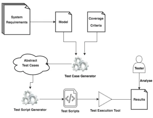
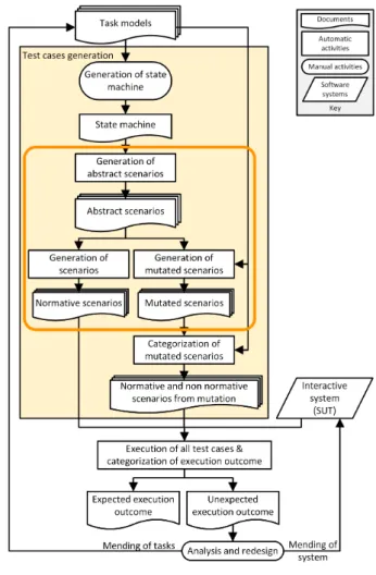
The MBT process (see Figure
1
) begins with the development of the abstract model of the SUT.
Obviously, the developed model must be validated, so it is assumed that the model is simpler than
the SUT, or at least easier to validate and maintain. Otherwise, the effort of validating the model
will be equal to the effort of testing the SUT (Utting et al.,
2012).
The next step is generating test cases from the developed model. The tests generated in
this phase are sequences of operations expressed on the model. To decide the number of tests
generated it is usual to define a coverage criterion over the model, and the generation process is
concluded when this coverage is achieved (Paiva,
2006).
Given that the generated tests are still sequences of abstract actions on the model, it is
necessary to convert them to concrete test cases, enabling their execution in the SUT. Finally,
the tests are executed, and the analysis of the results is performed, verifying if the results are the
expected.
2
.4.2
Model-Based Testing of User Interfaces
Model-Based Testing can be used on Graphical User Interface to test if the developed user interface
matches its specification. Several projects have been drawn up to allow the use of MBT in GUI
testing. These projects mostly focus in automating the process of testing. Nevertheless, work on
the application of MBT to GUIs has addressed several areas. Two particularly relevant ones are
which models to use as oracles (and how to obtain them) and how to guarantee a quality test
suite.
Following are some approaches to the application of MBT to GUIs.
GUITAR
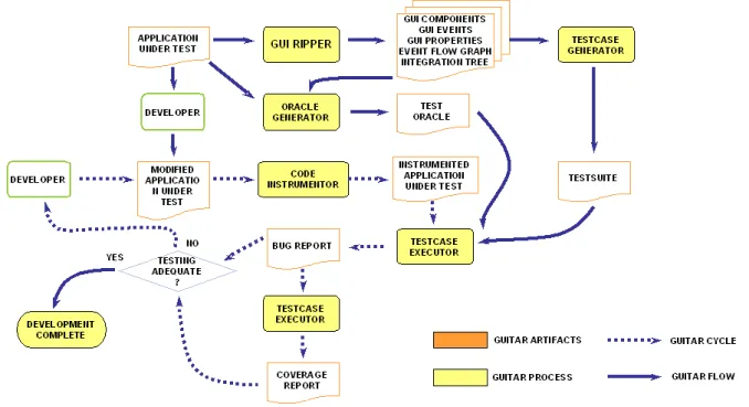
The first project developed in this area was by
Memon
(2001), who presented the GUITAR GUI
testing framework to automate GUI testing, based on a reverse engineering process. Built on a
modular architecture, this framework has a set of tools that allows the use of model-based tests
on GUIs (See Figure
9
). Using GUITAR, the tester can generate and execute test cases, verify the
correctness of the GUI and obtain coverage reports from the test execution.
Figure 2.: GUITAR Process (Taken from https://www.cs.umd.edu/~atif/GUITAR-Web/guitar_ process.htm)
2.4. Model-Based Testing 13
This tool applies a reverse engineering process to generate the representation of the GUI as an
integration tree and an event-flow graph, reducing the time and effort required to build the model.
From these artefacts, test cases are generated to test the GUI. The integration tree represents the
way the GUI components are integrated to form the complete GUI. It is based on the application’s
GUI hierarchy and is obtained through the GUI Ripper tool (Memon et al.,
2003). In this artefact,
each node of the tree represents one GUI component. Event-flow graphs represent all possible
interactions among the events in the GUI component and are obtained through the event-flow
graph generator. The generated models are easily analysed by their graphical visualisation. Despite
this, the structure of the models is not well documented, and the models cannot be built or edited
manually, this process is fully automatic and assured by the tool.
The GUITAR tool supports the generation and execution of three types of test cases, structural,
random and manual tests. After running the tests the tool provides a report which indicates the
GUI components tested and the coverage reached by the test.
Spec Explorer
Spec Explorer
1is a Microsoft Research tool that supports the application of MBT to native
applications. This tool works as an extension of Microsoft Visual Studio, and the main goal
is creating models of software behaviour, analysing those models with graphical visualisation,
checking the validity of those models, and generating test cases from the models. This tool is
suitable for testing Application Program Interfaces (API) but requires much effort to be applied
to GUI testing. Faced with this difficulty, some extensions were developed.
Paiva
(2006) developed an add-on for Spec Explorer, the GUI Mapping Tool, to adapt the
tool to perform tests on graphical user interfaces. The GUI Mapping tool tries to automate the
process of mapping between the elements of the model and the implementation, helping the user
to relate logical actions of the model with physical actions in the GUI (Paiva et al.,
2005). In the
end, the mapping information is generated automatically.
In this work, test methods based on formal specifications are used to systematise and automate
the GUI test process. However, the use of Spec# as the GUI modelling language means that the
developers would have to learn this language to adopt this proposal (Paiva et al.,
2005).
PBGT - Pattern-based GUI Testing
Another approach developed by
Moreira and Paiva
(2014) is Pattern Based GUI Testing (PBGT)
based on the UI Test Patterns concept that presents a set of test strategies that simplify testing
of UI Patterns on GUIs. This approach aims to promote the reuse of test strategies to test typical
behaviours in web applications.
PBGT is supported by a Eclipse plugin developed on top of the Eclipse Modelling Framework,
the PBGT Tool. The tool provides an integrated modelling and testing environment that supports
the crafting of test models based on UI Test Patterns, using a GUI modelling Domain Specific
Language (DLS) called PARADIGM. UI Test Patterns are elements within PARADIGM from which
it is possible to build models describing the GUI testing goals at a higher level of abstraction. The
models generated in this environment are used to generate and run test cases over a GUI.
So, this technique takes advantage of UI patterns to test the GUI more efficiently. However,
the tool is limited to the number of UI Test Patterns supported, and to the fact that UI patterns
must be found in the GUI under test.
TOM Framework
The TOM Framework is under development in the HASLab Laboratory of the University of Minho.
It is a set of tools designed to promote the introduction of advanced model-based testing
tech-nologies in the process of developing interactive software applications.
At the beginning of this dissertation, the Tom Framework consisted of two components: the
TOM Generator, and the TOM Editor.
TOM Generator:
TOM Generator contains the core of the TOM Framework. This component has a modular
architecture to ensure the adaptability of the framework and includes modules to read and translate
different types of models to its internal representation, and modules to generate, mutate and
execute the test cases. TOM Generator has been designed aiming at a low maintenance cost, and
its adaptation to different contexts, so the addition of new modules and the change/replacement
of existing one has a limited impact on the system.
The TOM Generator developed by
Rodrigues
(2015), was a Java Desktop application without
an interface. That is, to use the capabilities of the application it was necessary to change the
source code to specify the directories of the files (models, mappings, mutations and values) and
the parameters desired for the generation (such as algorithms, mutations to generate, browser to
use, ...). After this changes, the code was compiled and ran. The tests were generated to the
specified directory.
Despite the fact that the target audience of the application is composed of people with technical
knowledge in the area, the fact that the end user can view/change source code is not at all a
2.4. Model-Based Testing 15
Figure 3.: TOM Generator: Operating Mode
good option for an application. Thus, this component has undergone many changes throughout
this dissertation, being these presented in Chapter
4
.
TOM Editor:
The TOM Editor, developed by
Pinto
(2017), is a browser extension that supports the
develop-ment of a model of a web application GUI. The TOM Editor allows capturing the user interaction
with a web page while simultaneously defining the system model based on the user interaction.
Through the TOM Editor, the model of a GUI can be constructed in a semi-automatic way.
The purpose of the Editor is to facilitate the creation of the model preventing the user from
making modelling errors (Pinto et al.,
2017).
Other Approaches
Other authors have explored different approaches to reduce the production cost of the models.
Silva et al.
(2008) use a task model as an oracle. Task models are widely used to represent the
tasks the user can perform in a GUI. In this approach a task model of the SUT is used to generate
a state machine. This is achieved through the TERESA tool
2, which generates a representation
called Presentation Task Sets (PTS). From this representation and the mapping of the model to
the real interface, a graph is created from which the test cases are generated. As the task models
only represent the correct behaviour of the user, the use of mutations in the test cases was also
explored (Cruz and Campos,
2013), allowing the tests to cover variations such as user’s errors.
In addition to these approaches, many other authors have focused on integrating model-based
testing with graphical user interface testing.
Lelli et al.
(2015) developed an approach that focused
not on the cost but on the expressiveness of the model by proposing a modelling language capable
of dealing with advanced multi-event GUIs.
Bowen and Reeves
(2011) explore the applicability of
test-first development, an approach similar to test-based development, but using models of the
requirements as the basis for the tests, to GUI development.
2
.5
Summary
In this chapter, the thematic of software testing and its importance was introduced. A system
must be validated and verified to increase our confidence in its quality. With validation, it is
checked whether the system satisfies the requests of the users. With verification, it is investigated
whether the system was correctly implemented. Both qualities can be improved through software
testing, however, although it does not guarantee the complete absence of errors.
GUI testing is an essential component of the interactive software development process. In this
chapter, the different approaches to GUI testing were presented. There are several procedures for
testing a graphical user interface. Typically the different procedures are divided into one of two
kinds of techniques to test the graphical user interface. One focused on the usability of the GUI,
where the interest is the opinion and the difficulties of the users, and another more focused on
the implementation, where the importance is to ensure the system quality, both in behaviour and
in performance.
This chapter addressed model based testing, a technique that focuses on the quality of a
software implementation. Model-based testing is a technique that allows automating the process
of generation and execution of test cases to GUIs, at a much lower cost than manual techniques.
Some MBT tools that allow the use of the MBT to the GUIs were presented. The application
of MBT to GUIs permits the increase of software quality, reducing the time and effort spent to
develop the tests. The high degree of automation provided by this technique allows the testing of
GUIs more exhaustively and reliably. However, the success of this technique relies on the model
and the quality of the tool used to obtain the test cases.
Here we describe the development of the TOM Framework that aims to provide a more flexible
and adaptable support for the application of the MBT to the GUIs (Rodrigues,
2015). TOM
is similar to GUITAR as it adopts a plug-in architecture to provide flexibility and extensibility.
However, while GUITAR is based on reverse engineering the SUT for testing. TOM adds a focus
on flexibility and also on the modelling side.
Chapter 3
TOM Generator
In this chapter, one of the components of the TOM Framework, TOM Generator, is presented.
The improvements made to the generation process are also described.
TOM Generator is a crucial component of the TOM Framework. It consists of a set of flexible
and adaptable modules that aim to facilitate the application of MBT on GUIs.
3
.1
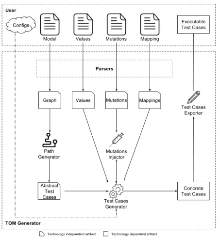
Generation process
The test case generation process used by the TOM Generator component is divided into several
steps, following the typical MBT approach, explained earlier (Subsection
2.4.1
). Figure
4
illustrates
the test case generation process used.
The component, after reading the GUI model, represents it as an oriented graph. With this
representation, abstract test cases (test cases that are independent of a concrete implementation)
are just paths in the graph. To obtain concrete test cases, after running the traversal algorithm,
the abstract test cases must be converted to source code in the required language. After obtaining
the concrete test cases, these are exported to executable test files.
Converting abstract test cases to concrete test cases requires the user to provide some settings,
such as the type of tests to be generated and the mutations to be introduced. Currently, the
framework has three modules to generate test cases, a module that allows the generation of web
interfaces tests, which later may be run by Selenium web-driver, another that creates scenarios
in Hamsters’ notation and the last one that generates test cases in JavaScript Object Notation
(JSON) notation. Depending on the type of tests to generate and the mutations to be introduced,
some configuration files may be needed to complete the model (Values, Mutations and Mappings).
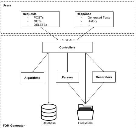
In summary, the TOM Generator process is divided into seven stages:
1. Reading and translating the system model
2. Generating a graph from the system model
3. Application of traversal algorithms on the previously obtained graph, generating abstract
tests cases
4. Converting abstract test cases into concrete test cases; Additionally, mutations can be
introduced
5. Creating the files with the executable test cases
6. Executing the tests
Figure 4.: Generation process
The format of the files necessary for the generation of test cases are presented below. The files
presented are based on the generation of tests for web applications. However, the only difference
is that for the other types of tests currently supported the mapping file is not necessary because
in that case the tests are generated at an abstract level.
3.1. Generation process 19
3
.1.1
Modelling the user interface
To represent a GUI the TOM Framework uses Final State Machines (FSM) as they are a recurring
approach to modal behaviour in software engineering.
In the representation of a graphical interface through a state machine, each state represents
a dialogue window or a page in a Web application. In each state, there may be transitions (links,
buttons, ...) to new states, which represent changes in the interface as a response to the user, or
several sub-states (form, menus, ...) (Rodrigues,
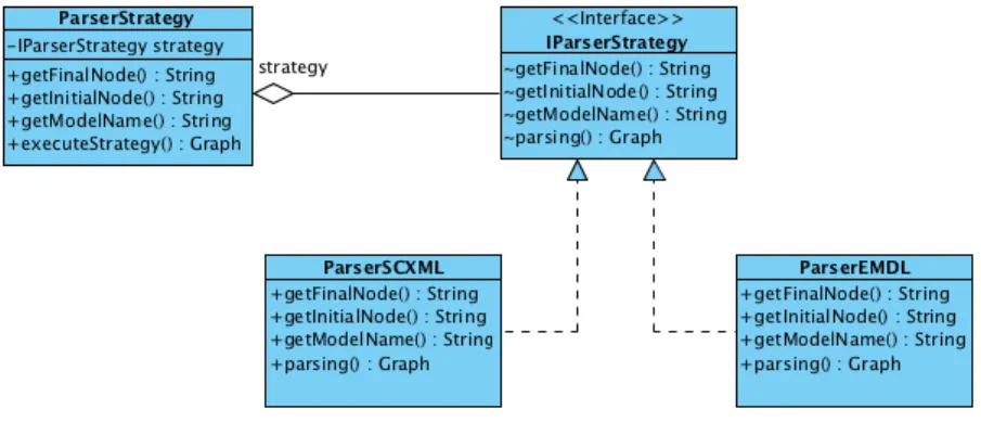
2015). For the model to be read by the tool,
it is necessary that the state machine is represented in one of the supported formats. Currently
parsers for State Chart XML (SCXML) and Emucharts are available. In this section, only the
representation of the state machine through a SCXML file is presented.
Listing
3.1
is an example of a model. In the presented excerpt a state can be observed (from line
3 to line 16), which is how a web page is represented. The presented state has a sub-state (from
line 6 to line 15) representing the filling of a form. The form has three input fields represented by
the ”send” tag (lines 7, 8 and 9) and a transition to a new state (from line 10 to 13). In case of
success, the ”submit” field from the transition is used (line 11), in case of error the ”error” field
(line 12). There are also two validations (line 4 and line 14), represented by the ”onentry” and
”onexit” tags. In case of non-completion of the form, the application can still transit to another
state through the state transition (line 5). The ”id” and ”label” attributes identify concrete values
defined in the mapping and value files, these values are used to complete the tests.
1 < s c x m l v e r s i o n = " 1.0 " ... n a m e = " E d i t o r " i n i t i a l = " 2 0 1 6 1 1 4 1 5 5 9 0 1 0 " > 2 3 < s t a t e id = " 2 0 1 6 1 1 4 1 5 5 9 0 1 0 " > 4 < o n e n t r y id = " 2 0 1 7 0 3 1 1 2 7 0 0 1 " t y p e = " d i s p l a y e d ? " / > 5 < t r a n s i t i o n id = " 2 0 1 6 1 1 4 1 5 5 9 0 1 2 " t a r g e t = " 2 0 1 6 1 1 4 1 5 5 9 0 1 1 " / > 6 < s t a t e id = " s i g n in " t y p e = " f o r m " > 7 < s e n d l a b e l = " s 2 0 1 6 1 1 4 1 5 5 9 0 3 2 " t y p e = " r e q u i r e d " e l e m e n t = " c h e c k b o x " / > 8 < s e n d l a b e l = " s 2 0 1 6 1 1 4 1 5 5 9 0 3 3 " t y p e = " r e q u i r e d " / > 9 < s e n d l a b e l = " s 2 0 1 6 1 1 4 1 5 5 9 0 3 5 " t y p e = " r e q u i r e d " e l e m e n t = " c h e c k b o x " / > 10 < t r a n s i t i o n t y p e = " f o r m " l a b e l = " 2 0 1 6 1 1 4 1 5 5 9 0 3 7 " > 11 < s u b m i t t a r g e t = " 2 0 1 6 1 1 4 1 5 5 9 0 3 8 " / > 12 < e r r o r t a r g e t = " 2 0 1 6 1 1 2 1 8 5 1 0 0 3 " / > 13 </ t r a n s i t i o n > 14 < o n e x i t id = " 2 0 1 6 1 1 4 2 0 8 0 0 1 " t y p e = " c o n t a i n s " / > 15 </ state > 16 </ state > 17 ... 18 </ scxml >
The construction of the SCXML GUI model and the description of the elements used to
describe the interaction and validation of the GUI are explained in detail by
Pinto
(2017).
Mappings and Values
During the development of the model, there are elements (such as concrete values for input fields,
or mappings between the model and Hypertext Markup Language (HTML) elements) necessary
to create executable tests that are not represented in the state machines, because we want to keep
the model abstract. Attributes are introduced (such as labels or ids) allowing us to map from the
abstract level to the concrete level. The separation between states machine, mappings and values
was done to make the models more general and easy to read
To associate the attributes entered in SCXML, the HTML element and the input data for
forms and validations, two types of files are used. To associate the HTML element of the SUT
and the corresponding attribute in the state machine, a mapping file is used. A values file is
used to fill in the form data information and the validations. The rules for building both files are
explained by
Pinto
(2017).
An example of a mapping file is shown in Listing
3.2
. This file is used to map the behaviour
defined in the state machine with the WEB application. For example, the element with the label
”s20161141559033” (from line 7 to 11) of the model will be found through its name (line 8), its
name is ”user[email]” (line 9) and the test must must fill in the text field (”sendKeys” line 10).
1 { 2 " 2 0 1 7 0 3 1 1 2 7 0 0 1 " : { 3 " h o w _ t o _ f i n d " : " c l a s s N a m e " , 4 " w h a t _ t o _ f i n d " : " header - full - t i t l e " , 5 " w h a t _ t o _ d o " : " g e t T e x t " 6 } , 7 " s 2 0 1 6 1 1 4 1 5 5 9 0 3 3 " : { 8 " h o w _ t o _ f i n d " : " n a m e " , 9 " w h a t _ t o _ f i n d " : " u s e r [ e m a i l ] " , 10 " w h a t _ t o _ d o " : " s e n d K e y s " 11 } , 12 " s 2 0 1 6 1 1 4 1 5 5 9 0 3 5 " : { 13 " h o w _ t o _ f i n d " : " c l a s s N a m e " , 14 " w h a t _ t o _ f i n d " : " t r a n s l a t i o n _ m i s s i n g " , 15 " w h a t _ t o _ d o " : " c l i c k " 16 } 17 ... 18 }
3.1. Generation process 21
An example of a values file is displayed in Listing
3.3
. This file is used to define values to
enter in the test cases. Resuming the previous example, the text to be sent to the element
”s20161141559033” will be ”admin@admin” (line 3).
1 [ 2 { " 2 0 1 6 1 1 4 2 0 8 0 0 1 " : " s u c c e s s f u l l y " } , 3 { " s 2 0 1 6 1 1 4 1 5 5 9 0 3 3 " : " a d m i n @ a d m i n " } , 4 { " s 2 0 1 6 1 1 4 1 5 5 9 0 3 5 " : " " } , 5 ... 6 ]
Listing 3.3: Example of Values configuration file
The values defined in this file are used in test cases to fill in forms or to perform validations.
In the form filling the values are entered in the input fields to simulate a user, in the case of the
validations, the values present in the file are compared with those present on the HTML during
the execution of the tests.
Mutations
The model used will typically represent the expected behaviour of the user. Hence, the test cases
generated directly from this model follow the path that the user should use. In other words,
the tests cases perform actions according to what is specified. This kind of tests is important
because it allows us to ensure that all relevant functionalities are tested. However, unpredictable
behaviours of the user are not covered.
Although positive tests are essential, they need to be complemented with tests that represent
the unexpected behaviour of the user (Rodrigues,
2015). To obtain this kind of tests, and thus
increase the quality of the tests generated, the TOM framework introduces mutations in the test
cases. Mutations are controlled changes to the test cases that introduce small errors in the test, to
see how the application reacts to the unexpected user behaviour. The purpose of these mutations
is to run the tests in a ’faulty’ way and cause the test to fail, increasing the reliability and quality
of the software.
The TOM Generator supports the mutation of test cases in a random way or through a
configuration file, in this file, the type of mutation to perform and the action where it is expected
to be performed can be specified (Pinto,
2017). This file can be generated from the TOM Editor,
or manually constructed,
Pinto
(2017) explains how to build this file to model the mutations to
perform in the tests. In Listing
3.4
an example of a configuration file for the mutations can be
seen. Analysing the file example, the element ”s20161141559035” of the model (line 4) should
undergo a ”lapse” mutation (line 3), and this mutation does not cause the test to fail (line 5).
1 [ 2 { 3 " t y p e " : " l a p s e " , 4 " m o d e l _ e l e m e n t " : " s 2 0 1 6 1 1 4 1 5 5 9 0 3 5 " , 5 " f a i l " : " 0 " 6 } , 7 ... 8 ]
Listing 3.4: Example of Mutation configuration file
The TOM Generator is capable of generating several types of mutations. However the
muta-tions generated depend on the type of tests to be generated, in the next section the mutamuta-tions
supported by each type of test are explained.
3
.2
Type of generated tests
As previously mentioned, after reading and interpreting the files that model the system, the TOM
Generator internally performs several steps to generate the executable test cases. Initially, abstract
(technology-independent) test cases are generated, and then the abstract test cases are converted
into concrete test cases, and finally to executable test cases.
Currently, the TOM Generator is adapted for the generation of three types of test cases:
• Web Applications: structuring actions in Selenium instructions, using annotations from
TestNG
• IRIT Scenarios: contains a list of steps to go through during the simulation in CIRCUS that
when co-executed with the task model detect if there is any deviation in expected behaviour
• JSON: contains a list of steps to go through the interface
In the following sections each of the types of tests supported by TOM Generator is presented.
3
.2.1
Web Applications
The generation of tests for Web Applications was the first type of test supported by TOM
Gen-erator, its development was started by
Rodrigues
(2015) and is improved in this dissertation.
The test cases are generated in Java and run using the Selenium and TestNG/JUnit
frame-works. Two frameworks are used because they complement each other. Selenium connects with
3.2. Type of generated tests 23