UNIVERSIDADE DA BEIRA INTERIOR
Ciências da saúde
Electrospun poly(ε-caprolactone) nanofibers for
bone regeneration and other biomedical
applications
Tiago António Martins Valente
Master Degree Thesis in
Biomedical Sciences
(2
ndcycle of studies)
Supervisor: Prof. Ilídio Joaquim Sobreira Correia (PhD)
UNIVERSIDADE DA BEIRA INTERIOR
Ciências da saúde
Produção de nanofibras de poli(ε-caprolactona)
por electrospinning para futura aplicação na
regeneração óssea e outras aplicações biomédicas
Tiago António Martins Valente
Dissertação para a obtenção do Grau de Mestre em
Ciências Biomédicas
(2º Ciclo de estudos)
Orientador: Prof. Doutor Ilídio Joaquim Sobreira Correia
iv
“Imagination is more important than knowledge. For while knowledge
defines all we currently know and understand, imagination points to all we
might yet discover and create.”
v
Acknowledgements
I would like to express my deepest gratitude to my supervisor, Professor Ilídio Correia, for all the support, teaching, guidance and broad multidisciplinary knowledge that shared with me during this journey. Moreover, I would like to thank him for doing the outmost to ensure all the necessary conditions for the development of this study.
I would also to thank to Professor António Morão for providing the microfiltration membranes necessary for one of the tasks of this project.
In addition, I would like to thank José Nunes, for all the help and for having done the filtration tests on the modified membranes.
Moreover, I would like to thank Eng. Ana Paula from the Optics department of Universidade da Beira Interior for the help in acquiring the lots of scanning electron microscopy images.
I would like to thank all of my group colleagues for all the advices, teaching and support during the good and the bad days. Principally, their friendship and joy was truly important to face all the difficulties during the development of this project.
I also thank to all of my friends for all the good times shared, advices and patience during not only the academic life, but also during my entire life.
Finally, I thank to my parents and my brother for granted me the possibility to make this master degree thesis. For all their education, support, advices, patience and love I do thank them a lot. Their presence in my life has been truly important in every decision I take.
vii
Abstract
Bone tissue is a complex and hierarchical structure with many functions in the body. Although this tissue has the capability for self-generation, large bone defects due to various diseases or fractures may need clinical treatment. However, the current clinical treatments are based on bone grafts and other bone substitutes, which have several limitations. Tissue engineering is a multidisciplinary field that emerged from the need to extinguish these clinical limitations. This vast field of science uses various tools in seeking for effective tissue regeneration. In this context, this work aimed the production of functional materials that mimic the nanostructure of bone tissue and therefore the cellular microenvironment, promoting bone regeneration. In this way, an electrospinning apparatus was mounted and optimized for the production of polycaprolactone nanofibers. Additionally, several electrospinning parameters that influence the morphology of the electrospun nanofibers produced were studied. For application in bone regeneration, the combination of polycaprolactone nanofibers with β-tricalcium phosphate scaffolds, mechanically more resistant, was investigated. Moreover, a preliminary study about the capacity for this system to allow controlled release of biomolecules was conducted through the incorporation of a model protein into the nanofibers. In order to characterize the biological properties of the systems produced, in vitro cytotoxicity assays were performed. These assays revealed that the polycaprolactone nanofibers produced are biocompatible and that the coating of β-tricalcium phosphate scaffolds with these nanofibers improve this biological performance, when compared to ceramic scaffolds without coating. The potentiality of nanofibers herein produced was also evaluated for the modification of microfiltration membranes. These membranes showed a large increase in the plasmid DNA rejection.
Keywords
Electrospinning, polycaprolactone, nanofibers, tissue engineering, coating of scaffolds, modification of membranes.
ix
Resumo
O tecido ósseo é uma estrutura complexa com diversas funções no organismo. Apesar deste tecido possuir uma capacidade de auto-regeneração única, defeitos ósseos com uma grande extensão causados por doenças ou fracturas podem necessitar de tratamento em meio hospitalar. No entanto, estes tratamentos são algo limitados, pois baseiam-se em transplantes e em substitutos ósseos compostos por materiais inertes. A engenharia de tecidos é uma área multidisciplinar que emergiu da necessidade de extinguir estas adversidades. Este vasto campo científico utiliza diversas ferramentas na procura de uma regeneração de tecidos mais eficaz. Neste âmbito, este trabalho pretende produzir materiais funcionais que mimetizem a nanoestrutura do tecido ósseo e, portanto, o microambiente celular, favorecendo a regeneração óssea. Com base neste pressuposto, montou-se um sistema de electrospinning e procedeu-se à sua optimização para a produção de nanofibras de policaprolactona. Adicionalmente, diversos parâmetros que influenciam a morfologia das nanofibras produzidas por electrospinning foram estudados. Para aplicação na regeneração óssea, a combinação das nanofibras de policaprolactona com scaffolds de β-tricálcio fosfato, mais resistentes mecanicamente, foi investigada. Adicionalmente, foi realizado um estudo preliminar sobre a capacidade deste sistema permitir a libertação controlada de biomoléculas, através da incorporação de uma proteína modelo nas nanofibras. O perfil citotóxico dos sistemas produzidos foi caracterizado através de ensaios in vitro. Estes estudos revelaram que as nanofibras de policaprolactona produzidas são biocompativeis e que o revestimento dos scaffolds de β-tricálcio fosfato com estas nanofibras melhora as propriedades biológicas em relação aos scaffolds cerâmicos sem revestimento. A potencialidade das nanofibras produzidas foi ainda testada na modificação de membranas de microfiltração. Este estudo demonstrou um aumento na rejeição de DNA plasmídico após o revestimento da membrana com as nanofibras.
Palavras-chave
Electrospinning, policaprolactona, nanofibras, engenharia de tecidos, revestimento de scaffolds, modificação de membranas.
xi
Table of Contents
Acknowledgments ... v
Abstract... vii
Resumo ... ix
List of Figures ... xiv
List of Tables ... xvii
List of Acronyms ... xix
Chapter I - Introduction
1 Introduction ... 21.1 Bone tissue ... 2
1.1.1 Formation and composition of bone ... 2
1.1.2 Structure of bone ... 3
1.1.3 Bone self-regenerative ability ... 5
1.1.4 Clinical treatment used for bone regeneration: motives and purposes ... 7
1.2 Tissue engineering ... 8
1.2.1 Biomaterials for bone tissue engineering ... 8
1.2.2 Nanotechnological approaches for bone tissue engineering ... 10
1.2.3 Electrospinning ... 13
1.2.4 Incorporation of growth factors into nanofibers ... 19
1.3 The application of nanofibers for biotechnological purposes ... 20
1.4 Objectives ... 22
Chapter II – Materials and Methods
2 Materials and Methods ... 242.1 Materials ... 24
2.2 Methods ... 24
2.2.1 Electrospinning setup ... 24
2.2.2 Preparation of PCL polymer solutions ... 24
xii
2.2.4 Scanning electron microscopy ... 25
2.2.5 Coating of the 3D β-Tricalcium phosphate scaffolds with PCL nanofibers ... 25
2.2.6 Coating the TCP scaffolds with BSA incorporated into PCL nanofibers ... 26
2.2.7 Proliferation of human osteoblast cells in the presence of the different scaffolds.26 2.2.8 Characterization of the cytotoxicity profile of the different scaffolds ... 27
2.2.9 Coating of the filtration membranes (FSM 0.45PP) with PCL nanofibers ... 27
Chapter III – Results and Discussion
3 Results and Discussion ... 293.1 Electrospinning setup ... 29
3.2 Optimization and characterization of the electrospun PCL nanofibers produced ... 31
3.2.1 Effect of polymer concentration on the nanofiber properties ... 32
3.2.2 Effect of the applied voltage on the nanofiber properties ... 34
3.2.3 Effect of the polymer flow rate on the nanofiber properties ... 36
3.2.4 Effect of the distance between the needle tip and collector on the nanofibers properties ... 38
3.2.5 Effect of the needle diameter on the nanofibers properties ... 39
3.3 Coating of the TCP scaffolds with PCL nanofibers ... 41
3.4 Evaluation of the cytotoxic profile of the different materials ... 42
3.5 Modification of microfiltration membranes (FSM 0.45PP) with PCL nanofibers ... 45
Chapter IV – Conclusions and Future Perspectives
4 Conclusions and future perspectives ... 48xiv
List of Figures
Figure 1 – Bone developmental processes ... 2
Figure 2 – Structure of bone ... 4
Figure 3 – Illustration of macro to nano structures of the bone ... 4
Figure 4 – Schematic representation of fracture healing ... 5
Figure 5 – Influence of architecture scale on cell binding and spreading ... 11
Figure 6 – Geometric phases of the polymer fluid in electrospinning process: Taylor cone, continuous jet and instability region ... 14
Figure 7 – Schematic setup for various nozzle types ... 18
Figure 8 – Schematic illustration of various electrospinning setups for control of the fibers alignment... 19
Figure 9 – Images of the electrospinning apparatus ... 30
Figure 10 – Images of the typical polymeric deposition area on the collector (a); the wood pallet used to assure user’s safety (b) ... 30
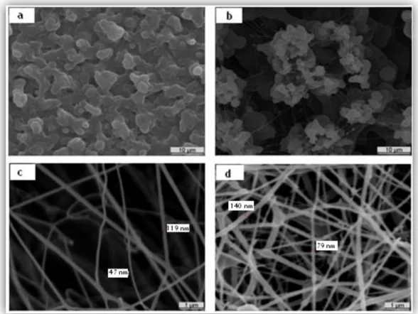
Figure 11 – SEM images of the samples obtained during the electrospinning optimization process ... 31
Figure 12 – Effect of the variation of polymer concentration on fibers formation ... 33
Figure 13 – Morphology of the nanofibers produced with the different applied voltage when the other parameters were held constant ... 35
Figure 14 – Effect of the flow rate on the morphology of the nanofibers ... 37
Figure 15 - Effect of the distance between the needle tip and collector on the morphology of the nanofibers, when all the other parameters are held constant ... 39
Figure 16 – Effect of the needle diameter on morphology of the nanofibers, maintaining the other parameters constant ... 40
xv Figure 18 – Optical microscopic photographs of human osteoblast cells after 24, 48 and 72 h of being seeded ... 43 Figure 19 – Cellular activities measured by the MTS assay after 24, 48 and 72 h of being seeded ... 44 Figure 20 – Commercial microfiltration membranes coated with PCL nanofibers ... 46 Figure 21 – Retention of pDNA for modified membranes (FSM 0.45PP) in function of the deposition time of the electrospun PCL nanofibers ... 46
xvii
List of Tables
Table 1 – Comparison of different methods for the production of polymer nanofiber scaffolds.. ... 12
Table 2 – Dielectric constants of the most used solvents applied in the preparation of electrospinning solutions ... 15
xix
List of Acronyms
ALP Alkaline phosphatase
BMPs Bone morphogenetic proteins BSA Bovine serum albumin
DMEM-F12 Dulbecco’s modified eagle’s medium EDTA Ethylenediaminetetraacetic acid EGF Epidermal growth factor
FBS Fetal bovine serum
FDA Food and Drugs Administration
HA Hydroxyapatite
RO Reverse osmosis
MF Microfiltration
MSCs Mesenchymal stem cells
MTS 3-(4,5-dimethylthiazol-2-yl)-5-(3-carboxymethoxyphenyl)-2-(4-sulfophenyl)-2H-tetrazolium reagent, inner salt
NF Nanofiltration
PCL Poly(ε-caprolactone)
pDNA Plasmid DNA
SEM Scanning electron microscopy TCP β-Tricalcium phosphate TGF- β Transforming growth factor - β
UF Ultrafiltration
VEGF Vascular endothelial growth factor
Chapter I
Introduction
Chapter I - Introduction
2
1. Introduction
1.1 Bone tissue
1.1.1 Formation and composition of bone
As part of the skeletal, bone plays several critical functions in the body: it is involved in structural support, is fundamental for locomotion, ensures protection for the internal organs (chest, cranium, spine), provides tissue base for the production of blood cells (haematopoiesis) and immune cells and form a mineral reservoir to maintain electrolyte homeostasis in the body [1, 2].
Bones are formed through two distinct pathways (figure 1): endochondral ossification gives rise to long bones, which include appendicular skeleton, facial bones, vertebrae and lateral clavicles; intramembranous ossification gives rise to the flat bones, comprising the cranium and medial clavicles [3]. Both types of ossification involve an initial condensation of mesenchyme, where cells are positioned adjacent one to another, and the successive formation of calcified bone [4]. However, intramembranous ossification accomplishes this directly, whereas endochondral ossification has an intermediate step in which an avascular tissue (cartilage) is formed before being mineralized and converted into bone tissue [3, 5].
Figure 1 - Bone developmental processes (Adapted from [3]).
Bone tissue is composed by mineral components (70%) and organic components (30%). The first one is almost all composed of an analogous form of hydroxyapatite [Ca10(PO4)6(OH2)],
Chapter I - Introduction
3 strontium [6]. The high surface/volume ratio and the crystals irregularity make them more soluble and easily mobilized to metabolic demands [6].
The organic part of the bone is composed by 2% of bone cells and 98% of organic components from the extracellular matrix (ECM) [6]. The principal organic component of ECM is collagen type I. This protein is a heteropolymer of three chains, each of them having the primary structure (Gly-X-Y)n, where X and Y are frequently proline or hydroxyproline [7]. Collagen is deposited in matrix along the mechanical stress lines and provides a backbone for the deposition of bone mineral [3, 6]. The mechanical properties of a bone are determined by this combination of materials. The inorganic phase is related to the resistance during compression, whereas the organic phase is responsible mainly for the viscoelastic properties in tension or shear [8].
The cellular elements in bone act as metabolic regulators and are responsible for the continuous remodelling of bone tissue [6]. Three types of cells coexist in bone: Osteoblasts are derived from marrow stromal fibroblastic stem cells. These cells are involved in the synthesis of a decalcified organic matrix, mainly constituted by collagen type 1, called osteoid. In this process, they produce large amounts of alkaline phosphatase, an enzyme that prepares the matrix for mineralization [9]; Osteocytes (derived from osteoblasts) are surrounded during the mineralization process in bone lacunae that have a network of canaculi, through which they make their metabolic exchanges and regulate the blood-calcium homeostasis [3, 6]; Osteoclasts (derived from the monocyte-macrophage lineage) are giant cells that produce enzymes, like acidic phosphatise, and are responsible for bone resorption [10].
Bone tissue is maintained by a balance of bone-forming and bone-resorbing cells. A malfunction in this equilibrium results in an excessive bone resorption that leads to anomalous conditions including osteoporosis, osteoarthritis, periodontitis and metastatic bone disease [11, 12].
1.1.2 Structure of bone
Morphologically bone can be described based on its density: cortical (compact) bone and cancellous (spongy or trabecular) bone [3, 11].
Cortical bone has as fundamental unit the osteon or Haversian system. Osteons consist of a central canal (Haversian canal) derived from intraosseous arteries and perforating canals surrounded by concentric rings of the matrix [11]. Due to the preferential orientation of osteons along the direction of the forces supported by the diaphysis, that arteriole is almost always disposed to length of bone. The Haversian canal communicates to each other by horizontal branches called Volkmann canals [6].
Cancellous bone presents a structure of intersecting trabeculae, following mechanical force lines, giving them a greater resistance to compressive forces. On the other hand,
Chapter I - Introduction
4 cortical bone is better able to withstand forces of extension-flexion and torsion forces [6]. The network of trabeculae is covered by an epithelial membrane of osteoblasts that can be activated to form more bone lamellae. On the trabecular surface the osteoclasts are involved in resorbing bone matrix and releasing minerals in Howship lacunae [6].
A schematic representation of both bone types can be observed in figure 2.
Figure 2 - Structure of bone: a) Cancellous bone. b) Cortical bone (Adapted from [3]).
The difference between cancellous and cortical bone is not only structural but also functional: cortical bone provides mechanical and protective functions, while cancellous bone is involved in metabolic functions, like the calcium homeostasis [3].
The hierarchical arrangement of bone tissue is represented in figure 3.
Chapter I - Introduction
5
1.1.3 Bone self-regenerative ability
Bone is highly vascularized and a very dynamic tissue, since it has both high mechanical properties and regenerative capacity [14]. This regenerative property is crucial for skeletal homeostasis and fracture repair. Unlike soft tissue healing, the regeneration of the natural bone tissue occurs without scar formation [15]. Fracture healing can be divided into three phases that form a continuous healing process after injury. In temporal order, this process comprises an inflammatory phase, a reparative phase and a remodeling phase [15, 16]. The overall process of bone repair is illustrated in figure 4.
Figure 4 - Schematic representation of fracture healing (Adapted from [15]).
Inflammatory phase
At the onset of bone damage, an inflammatory response is elicited during 1 week post fracture. This reaction helps to immobilize the fracture in two ways: pain causes the individual to protect the injury and the enlargement of the site (swelling) keeps the fracture from moving. The blood vessels rupture results in the activation of the complement cascade, platelet aggregation, and release of its granule contents, which triggers chemotactic signals [15, 16]. Hemostasis is guaranteed by platelets and by the formation of a hematoma. On the other hand, the hematoma become a fibrin network that provides pathways for cellular migration and serves as a source of signal molecules, that initiate cellular events essential to
Chapter I - Introduction
6 fracture healing. Lymphocytes, blood monocytes, macrophages and osteoclasts are attracted to the injury site and are activated to ―clean up‖ the wound of biological debris and to release cytokines that can stimulate angiogenesis [15, 16]. Growth factors that are released include insulin-like growth factor, vascular endothelial growth factor (VEGF), platelet-derived growth factor, transforming growth factor-β (TGF-β) and epidermal growth factor. These growth factors play important roles in the proliferation and differentiation of the mesenchymal stem cells (MSCs) [16].
Reparative phase
The reparative phase occurs before the inflammatory phase subsides and lasts for several weeks. A reparative callus tissue is formed at fracture site, which will be eventually replaced by bone. This callus enhances mechanical stability of the site by supporting it laterally. At this phase, the callus comprises of fibrous connective tissue, blood vessels, cartilage, woven bone and osteoid. While fracture wastes are being resorbed, pluripotent MSCs begin to differentiate in fibroblasts, chondroblasts and osteoblasts. As bone healing proceeds, the pH gradually becomes neutral and then slightly alkaline, which is optimal for alkaline phosphatase (ALP) activity and its role in the mineralization of the callus. The reparative phase includes endochondral bone formation and intramembranous bone formation [15, 16]. As the mineralization process evolves, the callus calcifies becoming more rigid and the fracture site is considered internally immobilized. During this stage, collagen fibers are not perfectly aligned and the callus is composed of an unorganized woven bone, which connects the two fracture ends. Proteins that regulate this phase include bone morphogenetic proteins (BMPs), parathyroid hormone-related peptide, osteopontin, osteocalcin, ALP and bone sialoprotein [16].
Remodeling phase
The remodeling phase is the final phase in fracture healing. In this phase the unorganized bone woven is replaced with a more organized structure and the excess of callus is resorbed. Remodeling of fracture repair consists of osteoclastic resorption of poorly located trabeculae and formation of new bone along lines of stress. This results in a gradual modification of the fracture region under the influence of mechanical loads, until an optimal stability is achieved and the bone tissue acquires similar architecture to that it had before the fracture occurred [15, 16]. The remodeling process is guided by expression of specific genes, protein synthesis and secretion. Osteoblast-osteoclast homeostasis is balanced by factors like macrophage colony-stimulating factor, tumor necrosis factor-α, receptor activator of nuclear factor κB and osteoprotegerin [16]. The events of this stage continue throughout
Chapter I - Introduction
7 adult life. Changes in estrogen levels, such as those occurring in postmenopausal women, can alter bone homeostasis; hence the bone loses its natural stability, what explains the increased susceptibility of women in comparison with men to bone fractures with aging [16].
1.1.4 Clinical treatment of bone: motives and purposes
In general, fracture healing is completed after 6-8 weeks after the initial injury occurs [15]. However, the healing capacity of bone has its limitations. Large bone defects due to trauma, fractures, cancer, periodontitis, osteoporosis and infectious diseases may not heal by themselves and result in non-union [17-19]. The size of bone fractures and defects that can be self-regenerated is designated as the ―critical size defect‖ and will not heal during the lifetime of the patient. Thus, for large defects, medical intervention is often required in order to allow bone regeneration [14, 20, 21].
The intervention mentioned above, requires the introduction of implantable materials as bone grafts to promote the healing process [22]. Autografts (bone transplanted from the self-patient) are considered the gold standard for bone repair due to their osteoconductivity, osteoinductivity and biocompatibility without the risk of pathogen transfer [17]. Although autografts exhibit the best clinical outcome, they suffer from several disadvantages such the limited quantity, size and shape of donor tissue, and the requirement of surgery at multiple sites to harvest donor tissue from the patient [46-49]. Allografts (bone transplanted from one individual to another of the same species) are osteoconductive and more abundant in supply than autografts, but carry out the risk of pathogen transmission and immune response, which can lead to graft rejection [17, 23, 24]. Xenografts (bone transplanted from animals of different species) hold risks of immune response and pathogen transfer between species, thus limiting their use [1, 21]. As a result, there is a constant need for bone substitutes due to severe bone injuries, degenerative diseases and reconstructive surgery. In recent times, there was a remarkable increase in the use of biomaterials for bone related surgical applications [25]. However, a gap remains to be filled since no synthetic material used until now, presents the native properties of bone, attending both biological aspects as well as mechanical requirements [25].
Chapter I - Introduction
8
1.2 Tissue engineering
In the last decade of the past century, tissue engineering emerges as a perspective to abolish the limitations of tissue grafts [26]. Tissue engineering is defined as an interdisciplinary field of research that applies methods of materials engineering and life sciences to create artificial constructs that restore, maintain or enhance tissues and organs functions [27, 28]. This field include a wide range of strategies employing cells, scaffolds, cytokines and genetic manipulation for the regeneration of tissue in vivo or the production of tissue in vitro [29]. Scaffolds are exogenous extracellular matrices designed to allow cell adhesion and proliferation and also to provide mechanical support until the newly formed tissue is structurally stabilized [30]. One approach to design exogenous extracellular matrices for tissue engineering is to mimic the functions of the extracellular matrix (ECM) components naturally found in tissues [30]. All artificial extracellular matrices used to engineer tissues have three fundamental roles: first, they facilitate the localization and delivery of cells to specific sites in the body; second, they define and maintain a structure for the formation of new tissues; and finally they guide the development of new tissues with their appropriate functions [30].
In bone tissue regeneration scaffolds are usually biodegradable and act as a temporary matrix for cellular proliferation and for extracellular matrix deposition. In addition, scaffolds work as a model for vascularization of new tissue (angiogenesis) and can also serve as carriers for biologically active agents, like growth factors that can enhance the regenerating potential of the system [31, 32].
An important aspect of tissue engineering science is the investigation of the interactions of cells with absorbable matrices and bioactive molecules (growth factors and cytokines), involved in the formation of new tissue [29]. The cells behaviour is strongly determined by a complex interaction of physical and chemical signals at the nanoscale [33]. Therefore, the incorporation of biological factors in scaffolds is common practice for tissue engineering applications. The purpose is to create a bioinspired extracellular environment that directs specific cell responses through activation of signalling cascades. These cascades will modulate gene expression and control important cell processes to allow tissue regeneration [33].
1.2.1 Biomaterials for bone tissue engineering
A biomaterial has been defined in the literature as ―a substance that has been engineered to adopt a structure which, alone or as part of a complex system, is used to direct the course of any therapeutic or diagnostic procedure, in human or veterinary medicine’’ [34]. The biomaterials are used in tissue engineering for the manufacture of scaffolds that
Chapter I - Introduction
9 provide structural support for specific cell attachment, spreading, migration, proliferation and differentiation [22, 31].
The first approach in the choice of a material to be used in the manufacture of a scaffold should be the evaluation of in vitro cytotoxicity, by using cell culture. Thus, the selection of the material to produce a scaffold is a crucial step in the construction of a tissue engineered product, since its properties are fundamental for the successfully application of this three-dimensional (3D) matrix in the production of biomedical devices [32].
Ideally, scaffolds for bone tissue engineering should be biocompatible for a good integration into host tissue without eliciting an immune response; osteoconductive, i.e. should possess interconnected pores with a proper size to allow cell infiltration, neovascularization and removal of metabolic wastes; should be mechanically resistant to withstand local stress and provide structural support during the new bone tissue growth and remodelling [17, 35, 36]. The degradation products of the biomaterial should not be toxic and should be safely removed from the biological system. If this degradation rate is finely tuned, the scaffold is degraded in such a way that the scaffold is completely resorbed by the time that the bone defect is totally regenerated [17]. In addition, scaffolds should also possess a bioactive behaviour, promoting osteointegration and stimulating the growth and differentiation of bone cells, as well as be able of be sterilized without losing their bioactivity [25, 37].
A vast diversity of materials including ceramics, composites and polymers has been studied for the production of scaffolds for bone tissue engineering. These materials can be synthetic or natural, have different properties and show different degradation rates [22, 37, 38].
Ceramics such as hydroxyapatite (HA), calcium phosphates and bioactive glasses have been attracted special attention, due to their excellent biocompatibility along with their osteoconductive and osteoinductive properties [39]. Depending on their composition, particle size and production process, ceramics can have various degrees of bioactivity, which is the ability to chemically bond and be integrate into living bone through the formation of HA [40]. However, these materials are brittle and have low mechanical stability, making them unsuitable for load bearing applications [41].
Biodegradable polymers can avoid some of the drawbacks of ceramics. Natural polymers obtained from animal or vegetal sources, include proteins such as collagen, fibronectin, and polysaccharides such as chitosan, starch and hyaluronic acid [22, 42]. The major advantages of these materials are their great structural similarity to natural ECM constituents, their low immunogenic potential, as well as their high abundance [22, 42]. Synthetic polymers have great advantages because their structure, composition and, consequently, their properties can be tailored to specific needs [22, 43]. Polymers biodegradability can be controlled by different ways. Some polymers can suffer hydrolysis, others can be degraded by enzymatic pathways [43]. In addition, they are more ductile than ceramics and some can, in their solid form, reach mechanical compression strength close to
Chapter I - Introduction
10 that of cortical bone [43]. The most widely investigated are poly(lactic acid), poly(glycolic acid), poly(ε-caprolactone) (PCL) and their copolymers such as poly (L-lactic-co-glycolic acid) [44-46]. Among these polymers, PCL has been receiving special attention in the last years, which contributed to a huge increase in its applications [47]. PCL is a semi-crystalline aliphatic polyester, rather hydrophobic, with a slower degradation rate. The main cause of PCL polymers degradation is hydrolysis. This degradation is affected by size, crystallinity of the polymer, the pH and temperature of the environment [48, 49]. Furthermore, PCL is approved by Food and Drugs Administration (FDA) for biomedical applications, has low cost and can be used in diverse scaffold fabrication technologies [47]. The major disadvantages of synthetic polymers are that their properties can differ, even for the same composition, as a function of manufacturing, temperature, sterilisation, local environment and design geometry [43]. Furthermore, they lack osteoconductivity, bioactivity and have low stiffness that is desired for bone tissue engineering [50] [51]. Notwithstanding, a polymer-based scaffold can have these properties if the scaffold contains a sufficient amount of bioactive materials such as bioceramics [52, 53].
In this way, polymer/bioceramic composite scaffolds represent a convenient alternative for applications in bone tissue regeneration due to the possibility to tailor their various properties depending on the particular needs. Composites have shown to be more effective for the enhancement of both mechanical properties and bioactivity, in comparison to ceramic and polymers alone [48, 54, 55].
1.2.2 Nanotechnological approaches for bone tissue engineering
Until few years ago, emphasis was placed on macroporous features and mechanical properties of the scaffolds. As the field of tissue engineering evolved, more importance was been given to biological aspects and to the functionalization of the scaffolds [56-58]. The importance of the reproduction of the cellular microenvironment to the regulation of essential cellular functions, such as adhesion, proliferation, morphogenesis and differentiation, showed that the reproduction of the ECM is crucial for tissue regeneration [56, 59].
Natural bone is a complex hierarchical structure of tissue and a true nano-composite of collagen nanofibers reinforced by hydroxyapatite crystals [60]. The fibrous component of the ECM provides structural support as well as surface for cell adhesion and can also regulate cell shape and migration patterns based on composition and arrangement [61]. Besides, fibrous proteins also act as storage locations for the release of bioactive molecules and growth factors upon release by proteolytic cleavage [61]. Therefore, recent efforts are being done to the production of new functional biomaterials that reproduce these hierarchical structures, though using complex chemistry and tedious procedures [62].
Chapter I - Introduction
11 New bone tissue engineering methodologies and progress in nanotechnology have triggered the use of nanostructures as scaffolds for the purpose of tissue engineering [13, 63, 64]. Techniques for creating nanoscale features, patterns and particles have emerged and represent promising strategies to reproduce the natural structure and functions of the ECM. As a result, enhance communication between cells and biomaterials and promotes the desired cell behaviour [33]. Among the various nanostructures, nanofibers are very attractive for the biomedical applications, since they present a similar fibrous structure to that of natural ECM. The nanofibers can be organized into various porous architectures and possess a high surface area to volume ratio [65, 66]. On the other hand, although some nanostructures, such as nanoparticles, may have a higher surface area, nanofibers have the advantage that they can be fabricated into more sophisticated macroscopic structures such as sutures and scaffolds [65]. Indeed, the architecture and the scaffold porosity scale have an important role in cell adhesion and in cell answer to an external stimulus (figure 5) [67].
Chapter I - Introduction
12 In this way, different methods for the production of polymer nanofiber scaffods have been investigated (Table 1).
Table 1 - Comparison of different methods for the fabrication of polymer nanofiber scaffolds (adapted from [61]).
Advantages Disadvantages
Electrospinning
Easy to setup Cost effective
High level of versatility, allows control over various features
Vast materials selection
- Poor cell infiltration into the core of the scaffolds - Toxic solvents often used
Self assembly
Easy incorporation of cells during fiber formation 3D pore arrangement
Injectable for in vivo assembly
- Complex procedure - Lack of control of fiber
orientation and arrangement
- Limited fiber diameter
Phase Separation 3D pore arrangement
- Complex procedures - Lack of control of fiber
arrangement
Bacterial Cellulose
Low cost High yield
- Limited material selection - Lack of versatility for
functionalization
Templating
Vast materials selection
Control over fiber diameter and length - Sacrificial materials - Limitation on fiber dimensions and arrangement Drawing
Vast materials selection Simple procedure
- Low productivity (One single fiber at a time) - Difficult to form fibers with
consistent diameter
Extraction Natural materials
- Limited material selection - Limited control of fiber
diameter and length
Vapor-Phase Polymerization
Polymer synthesized directly into nanofibers
- Limited control of fiber diameter and length - Limited material selection - Complicated procedures
Kinetically
controlled solutions synthesis
Polymers synthesized directly into nanofibers
- Limited control of fiber diameter and length - Limited material selection - Complicated procedures
Chemical
polymerization of Anilline
Polymers synthesized directly into nanofibers
- Limited control of fiber diameter and length - Limited material selection - Complicated procedures
Chapter I - Introduction
13 Nanotechnological approaches have a great potential for medical applications. In particular, the development of electrospinning is very important for health care applications since it is a relative quick, simple and cost-effective method for producing nanostructured materials desirable for many biomedical applications such as tissue engineering [65, 68, 69].
1.2.3 Electrospinning
Electrospinning has become a popular tissue engineering technique because is capable of producing fibers at the micrometer and nanometer scales, which can mimic the cellular microenvironment and therefore enhance cell adhesion and proliferation [52].
The typical electrospinning setup consists of a high power supply, syringe pump, syringe, metallic needle, and a grounded collection device [70]. In this process, a polymer solution or melt is loaded into a syringe with an attached needle [70]. The syringe pump is used to control the flow rate at which the solution is feed [71]. A high voltage is applied to the polymer solution, which overcomes the surface tension of the polymer fluid at the tip of the needle to form a charged jet [66, 72]. When the induced electrical field is above a critical value, the pendant drop at the end of the needle tip is deformed and forms a conical shape, known as the Taylor Cone [73, 74]. This phenomenon was discovered in 1969 by Sir Geoffrey Taylor and shows that a conducting fluid can exist in equilibrium in the form of a cone under the action of an electric field, where a jet can be formed at the apex of the cone, if a continuing supply of the liquid is provided [75, 76]. Due to the electrical force, the jet is accelerated. During the acceleration, however, the viscous resistance prevents the jet from moving forward, as a result, there is a decrease in acceleration [74]. In this moment, any small perturbation will prevent its straight movement, and instability occurs [74]. The three different geometric phases of the polymer fluid during the electrospinning process are illustrated in figure 6. As this jet proceeds through the air, the solvent evaporates, with the consequent dry and stretching of the polymer jet till the deposition of a polymer fiber mesh on the grounded collector [73, 77].
In the typical process, the deposited fiber mesh consists of random, non-woven and highly porous mats [59, 67]. Fiber diameter is one of the features that is very important in this structures, since the smaller the diameter of the fibers, more surface area is available for cell activities and drug loading [65]. Moreover, some authors refer that nanoscale fibers in the lack of beads, enhance performance in terms of cell response, relatively to the microscale counterpart [59]. These features, along many others, like the morphology, arrangement, pore size, surface topography and chemistry, can be controlled by varying parameters affecting electrospinning [78, 79]. The electrospinning parameters can be divided in three main groups: solution parameters, processing parameters and environment parameters [78].
Chapter I - Introduction
14
Figure 6 - Geometric phases of the polymer fluid in electrospinning process: Taylor Cone, continuous jet, instability region (Adapted from [74]).
Solution related parameters
Accordingly to what is described in the literature, tailoring the different electrospinning parameters, a multitude of natural and synthetic polymers can be used for the production of fibers at the micro and nano scales [80, 81]. The properties of the solution are the most important factors that define the electrospinnability of a polymer [78]. These properties include solution concentration, viscosity, surface tension, conductivity, dielectric constant and average molecular weight of the polymer [82, 83]. The solution concentration should be high enough to allow molecular chain entanglements [84]. If this minimum concentration is not reached, fiber formation is not achieved, instead, leads to the production of droplets when electrified, a process known as electrospraying [84, 85]. For higher concentrations the formation of beads decreases and smooth fibers can be achieved [86]. Nonetheless, the solution concentration is also directly correlated with the viscosity. Thus, a solution with too high concentration can present an excessively viscosity, preventing
Chapter I - Introduction
15 the elongation of the jet and, in this way, avoids the fiber formation [86]. On the other hand, the polymer molecular weight also influences the viscosity of a solution. The molecular weight must be high enough to prevent the breakdown of the molecular chains during the electrospinning process, but not too high to not confer a huge viscosity to the solution [78, 87]. The surface tension is a resistant force that acts in the solution at the needle tip [82]. Higher surface tension increase the difficulty of the formation of a stable jet, leading to an increase of beaded structures formation [83, 88]. This can be reduced by adding a surfactant or salt to the solution [88]. This addition increases the charge density in the ejected fluid, leading to stronger elongation forces due to self-repulsion of charges under the high electrical field. In this form, thinner and more uniform electrospun fibers can be produced due to the increased conductivity [89-91]. A vital selection that influences the solution properties is the solvent used [83]. Normally, this choice is based mainly on the solubility of a polymer in the solvent. Nevertheless, this is not totally correct, given that a higher solubility is not directly related with a higher conductivity of the fluid itself [82]. A ―good‖ solvent for electrospinning has the capability to dissolve the polymer and possesses, at the same time, a high dielectric constant. This allows the carry of a relatively bigger amount of charges, enhancing the continuous stretching of the jet, resulting in smaller diameter fibers without beads [91-93]. The dielectric constants of some of the most used solvents are presented in table 2.
Table 2 - Dielectric constants of the most used solvents applied in the preparation of electrospinning solutions (Adapted from [78]).
Solvent Dielectric constant
2-propanol 18.3 Acetic acid 6.15 Acetone 20.7 Acetonitrile 35.92-37.06 Chloroform 4.8 Dichloromethane 8.93 Dimethylformamide 36.71 Ethyl acetate 6.0 Ethanol 24.55 m-Cresol 11.8 Methanol 32.6 Pyridine 12.3 Tetrahydrofuran 7.47 Toluene 2.438 Trifluoroethanol 27.0 Water 80.2
Chapter I - Introduction
16 Process related parameters
The process parameters used in electrospinning include the electrical potential applied, the distance between the needle tip and the collector, the diameter of the needle and the feed rate (flow rate) [78, 88]. The high voltage applied to the solution is crucial for the resulting morphology of the fibers. A minimum threshold voltage is required for the generation of sufficient charges on the fluid and, subsequently, the formation of the fibers [94]. Depending upon other parameters, such as flow rate and fluid viscosity, higher voltages may be necessary to allow the stabilization of the jet [95]. In general, when the voltage increases, higher elongation forces and, thus, more stretching is imposed to the jet, resulting in a decrease of the fibers diameter produced [94, 96]. However this is not consensus, some authors refer that there is not a significantly influence of the electric field on the fiber diameter, and for higher voltages there is also a greater probability to occur bead formation [94, 96, 97]. Moreover, other authors have reported that when higher voltages are applied, more polymer is ejected which results on larger fibers diameter [94, 98]. The tip to collector distance is another parameter that tailors the fiber diameter and morphology. It is considered that this distance has to be sufficient to allow the fibers to dry before reaching the collector and to prevent the formation of a beaded morphology [94, 97]. Although it is considered not so significant as other parameters, an increase in this distance decreases the fiber diameter and for greater distances the formation of beads can also occur [94, 97]. Polymer flow rate influences jet velocity and the material transfer rate. This is very important since the flow of solution through the needle must be sufficient do replace the solution ejected and, in this form, jet be maintained [94, 97]. High flow rates may contribute to the increase of fiber diameter and an excessive flow rate augment the beads defects due to the insufficient time for the solvent to evaporate, before reaching the collector [94, 97, 99]. Other parameter that can influence the morphology of the fibers is the needle diameter. Accordingly to some authors, the fiber diameter seems to decrease by decreasing the needle diameter [96]. Moreover, Wang and coauthors have studied the effect of the needle diameter in the efficiency of electrospinning process and verified that a bigger needle diameter results in a high number of fibers produced [100].
Ambient related parameters
In electrospinning environment conditions such as temperature, humidity and air velocity in the electrospinning chamber should also be taken into account [101]. As expected, there is an inverse relationship between viscosity and surface tension of the solution and temperature [94, 101]. Moreover, solution conductivity gradually increases with temperature, thus contributing to improve the solutions electrospinnability [101, 102]. The high rate of solvent evaporation at higher temperatures also facilitates the removal of the solvent, which
Chapter I - Introduction
17
may contribute to the variation of the fiber diameter [102]. The variation in humidity also has an effect in solvent evaporation rate. When humidity is very low, a volatile solvent may dry so fast that electrospinning process only is possible for little time before the needle tip is clogged [94, 102]. On the other hand, at higher relative humidity, there is a favourable adsorption of water on the polymer solution jet due to the higher partial pressure of water in the atmosphere. This does not allow the complete drying of the jet and results in fibers with pores at the surface [78, 94, 102]. The air velocity in the electrospinning chamber is also important due to the relative low mass of the fibers produced. Its spinning motion can be brutally affected by even the smallest air flow between the tip and collector [75]. Based on this fact, some authors have investigated the implementation of systems whereas the deposition and morphology of the fibers can be controlled by adjusting the air flow in the electrospinning chamber [103].
Advanced electrospinning modifications
In addition to the diverse parameters herein explained, the typical electrospinning apparatus can also be target of various modifications in order to tailor the fiber deposition and orientatio to enhance the function of the resulting fibrous structures. These modifications consist mainly on changing nozzle system (capillary) and deposition collectors [70, 104, 105]. Depending on the application, multiple and coaxial nozzles can be implemented (Figure 7).
An array of adjacent nozzles can improve fibers production efficiency at the same time that possibilities the introduction of different materials into the fibrous electrospun structure [106]. In this case, the electrical potential applied must be rigorously controlled for all the adjacent capillaries, which require special attention on the electrical field interferences between nozzles, toward the production of uniform fibers [106, 107].
In coaxial electrospinning, two polymers are ejected simultaneously from two concentrically nozzles, which results in an inner core-shell structure [104, 108]. This method is useful for the production of dual composition fibers and micro/nanotubes that can also be used for controlled drug release and bioactive tissue scaffolds [108, 109].
Chapter I - Introduction
18
Figure 7 - Schematic setup for various nozzle types: a) coaxial electrospinning (Adapted from [110]), b) multiple nozzle electrospinning (Adapted from [106]) .
The instability of the jet results a random orientation of the fibers deposited on the collector. For many applications, the control of spatial orientation may be required. Alignment of electrospun fibers can be achieved, for example, by using a rotating drum or a pair of split electrodes as a collector, or through the introduction of an external electric field (figure 8) [105, 111].
Several studies revealed that well-aligned fibers are generated when a cylinder or disk rotating at high speed is used as collector [111]. The rotation movement increases mechanical properties through better fiber arrangement in the direction of rotation [104]. Borhani and coworkers demonstrated that when the rotation speed of the drum increases, there is an increase in the density of the nanofibers mats, resulting in a decrease of the bulk porosity of the nanofiber structures [112]. However, a higher rotation speed may also cause fiber discontinuity [70]. This method has been used for neural tissue and blood vessels engineering, where the alignment properties are essential for guiding cells migration [113-115].
The geometrical configuration of a collector has also been reported as a mean to generate uniaxially nanofibers arrays [106]. By collecting the nanofibers across the void gap of two parallel conductive collectors, highly aligned nanofibers are produced [111]. This method is very convenient when there is the need to transfer the aligned fibers onto other substrates for further processing and applications [106]. One of the major drawbacks of this method is its low productivity. This results from the fact that the most nanofibers are randomly deposited on the electrode surface instead of filling the gap [105].
In more complex setups, auxiliary electrodes can be used to create more ordered electrospun fiber structures [104]. These auxiliary electrodes may influence the deposition location of the electrospun fibers, aligning fibers and forming patterns [105]. Some authors reported that in magnetic-field-assisted electrospinning, the jet direction and diameter can
Chapter I - Introduction
19 be determined by the magnetic field gradient [116]. Moreover, other authors demonstrated that by properly implementing an external magnetic field, they can prevent instabilities in the multiple nozzle electrospinning [117].
Figure 8 - Schematic illustration of various electrospinning setups for control of the fibers alignment: a) Pair of split electrodes as a collector (Adapted from [105]); b) Magnetic-field-assisted electrospinning (Adapted from [118]); c) Cylindrical rotation drum as a collector (Adapted from [119]).
1.2.4 Incorporation of growth factors into nanofibers
In order to accelerate and stimulate bone regeneration, addition of active biological molecules in the bone defect site is considered an effective and safer therapeutic method [120]. Among them, special interest has been given to BMPs, which are members of the TGF- β superfamily [121]. Of these molecules, the isoforms BMP-2, BMP-6, BMP-7 and BMP-9 are considered the most bioactive molecules for osteogenesis [120, 122, 123]. They promote migration of mesenchymal stem cells and their differentiation into osteoblasts [124].
Apart from osteoinduction angiogenesis is another essential process that is fundamental for bone regeneration and it is involved in the initiation of fracture healing. This process of neovascularisation is essential to supply nutrients, oxygen and remove products from the metabolism [125]. VEGF stimulates proliferation and migration of endothelial cells that mediate the sprout of the vascular network. Thus, the addition of VEGF in ischemic
Chapter I - Introduction
20 tissue region may have positive results in bone regeneration [126]. However, when VEGF is released too rapidly or in an uncontrolled manner, various adverse effects can occur [127].
Other studies refer that BMPs and VEGF play an essential role in cell communication during osteogenesis and angiogenesis. Moreover, they report that the peak of VEGF expression occurs in the early days of bone healing and the peak of BMPs occurs at a later phase [124]. The presence and time of appearance of these signal molecules are of special relevance, since they can be used in tissue engineering approaches to improve tissue formation in vitro and in vivo [3]. Therefore, the temporal control of the tissue regeneration process is very important and it involves various agents at different times [128]. Nonetheless, a controlled delivery system that mimics endogenous growth factor production remains a challenge with conventional scaffold strategies [128].
In this work, the possibility of growth factors incorporation into nanofibers was studied. This is very important since growth factors act as cell signals that promote their proliferation and contribute for bone tissue regeneration.
1.3 The application of nanofibers for biotechnological
purposes
The filtration membranes are fundamental for separation of molecules from mixtures. The membranes potential for this purpose was recognized for the first time 160 years ago, when Pfeffer and Graham were studying osmosis, and verified different rubber bands permeabilities to gases. However, the use of membranes for separation processes can be considered relatively recent [129]. Membranes can be defined as a selective barrier (selectively transfers mass between two phases) that allows a partial separation of components from a mixture, which are separated without changing their characteristics. The majority of the applications use synthetic membranes, which can be prepared either with inorganic materials like ceramics, or with organic materials including all types of polymers. There are several methods used for the production of membranes that are dependent on the membrane material and its application [129].
The separation processes using membranes can be classified based on the driving force they use to perform the separation. One of the most used processes is the one in which the driving force is the difference of pressure across the membrane. Within this, can be distinguished four types, microfiltration (MF), ultrafiltration (UF), nanofiltration (NF) and reverse osmosis (RO). The size of the solutes that membranes have the capacity to retain, decreases as it passes from MF to the RO.
In biotechnology the most common membrane technologies include operations of MF and UF. The pore size of the MF membranes varies between 0.05 µm and 10 µm, which make these membranes suitable for retention of suspended solids, emulsions and bacteria. The UF
Chapter I - Introduction
21 membranes are also seen as porous; however, the pore size is considerably smaller, ranging between 10 nm to 50 nm. This feature makes these membranes mostly used to retain macromolecules. As a consequence, these membranes can be used to concentrate and purify solutions of large molecules, which comprise the major biopolymers such as DNA, RNA or proteins. The scientific research into the production of plasmid DNA (pDNA) from fermentation extracts has grown considerably in recent years, driven by the possible use of this macromolecule in gene therapy [130]. Several studies have been done on the possible use of membrane filtration in the process of pDNA purification. In particular, it is important to underline that ultrafiltration can be very useful for the purification of Escherichia Coli lysates, which demonstrated the feasibility of this process [131, 132].
The modification of membranes is the process by which the properties of a membrane are altered in favour of a better selectivity and / or productivity. The modification of MF membranes was done in order to prove the versatility of the electrospun PCL nanofibers. The objective was to obtain a modified membrane with a pore radius considerably smaller, in order to retain macromolecules such as pDNA.
Chapter I - Introduction
22
1.4 Objectives
The combination of properties such as structural support, cellular support and controlled delivery of specific biological agents in a unique system, seems to be one way to achieve the desired efficiency in bone tissue regeneration [133, 134]. Knowing the nanotechnology potential to reproduce the extracellular environment, it may be a valuable tool for enhancing cell-biomaterial communication and promote better cellular response [33]. In the present study we used an electrospinning technique to reproduce the cellular microenvironment of the bone ECM by means of the fabrication of a PCL electrospun nanofibrous structure. Additionally, different applications for the nanofibers produced were studied. The present master thesis work plan had the following aims:
- Setup of an electrospinning apparatus; - Optimization of the electrospinning process; - Electrospun of PCL nanofibers;
- Incorporation of a model protein into PCL nanofibers; - Coating 3D scaffolds with these nanofibers;
- Evaluation and characterization of the biological properties of the systems produced; - Modification of MF membranes with the electrospun PCL nanofibers.
Chapter II
Materials and Methods
Chapter II - Materials and Methods
24
2 Materials and Methods
2.1 Materials
A high power voltage supply (Spellman CZE1000R, 0–30 kV) with very low-current output (0-300 μA) was purchased from Spellman High Voltage Electronic Corporation (West Sussex, United Kingdom). A syringe pump (KdScientific, KDS-100 series), polycaprolactone ( w=14,000 g/mol), acetone, phosphate-buffered saline, bovine serum albumin (BSA),
dulbecco’s modified eagle’s medium (DMEM-F12), ethylenediaminetetraacetic acid (EDTA), L-glutamine, penicillin G, streptomycin, Amphotericin B and trypsin were purchased from Sigma-Aldrich (Sintra, Portugal). 3-(4,5-dimethylthiazol-2-yl)-5-(3-carboxymethoxyphenyl)-2-(4-sulfophenyl)-2H-tetrazolium reagent, inner salt (MTS) and electron coupling reagent (phenazine methosulfate; PMS) were purchased from Promega. Fetal bovine serum (FBS) was purchased from Biochrom AG (Berlin, Germany). Human osteoblast cells (CRL-11372) were purchased from American Type Culture Collection (VA, USA). Pierce BCA protein assay
reagent A and B were purchased from Thermo Scientific. Tris Base was purchasedfrom Fisher Scientific. Microfiltration membranes (FSM 0.45PP) were purchased from Alfa Laval (Algés, Portugal). β-Tricalcium phosphate (TCP) powder was purchased from Panreac (Barcelona, Spain).
2.2 Methods
2.2.1 Electrospinning setup
The system herein used to carry out the electrospinning process is composed of a high power voltage supply (Spellman CZE1000R, 0–30 kV), a syringe pump (KDS-100), a syringe fitted with a stainless steel blunt end needle and an aluminium plate as the conductive collector (10cmx12cm). The needle is positively charged by the power supply and the metal collector is grounded. The charged tip and grounded collector form a static electric field between them to provide the driving force that enables fiber formation [80, 94].
2.2.2 Preparation of PCL polymer solutions
PCL was dissolved in acetone under vigorous magnetic stirring, at different concentrations (7-27% (w/v)). To facilitate PCL dissolution, the various solutions were heated at 50 ºC for a while and were sonicated for 1 hour [135].
Chapter II - Materials and Methods
25
2.2.3 Optimization of the electrospinning process
The previously prepared solutions were transferred into a 10 ml syringe, fitted with a blunt end needle. The flow rate of the PCL solution was controlled by the syringe pump. In this study, different electrospinning parameters were tested: electric voltage applied to generate the electrical field (10–27 kV); distance between the needle tip and grounded collector (10–20 cm); diameter of the needle (0.5-0.9 mm); flow rate (0.5-7.0 mL/h). The collection of samples for the optimization process lasted 1 min. Electrospinning was performed at room temperature [75, 135].
2.2.4 Scanning electron microscopy
The morphology of electrospun fibers was analyzed by scanning electron microscopy (SEM). Samples were air-dried overnight and then mounted on an aluminium board using a double-side adhesive tape and covered with gold using an Emitech K550 (London, England) sputter coater. The samples were then analyzed using a Hitachi S-2700 (Tokyo, Japan) scanning electron microscope operated at an accelerating voltage of 20 kV and at various amplifications [136, 137]. The diameter of the electrospun fibers was measured in a software from the microscope. During the measuring process, 2 fibers had been selected and assayed in every SEM micrograph.
2.2.5 Coating of the 3D β-Tricalcium phosphate (TCP) scaffolds with
PCL nanofibers
The coating of the TCP scaffolds produced in our group with PCL nanofibers was performed by the typical electrospinning process. TCP scaffolds were placed between the needle tip and aluminium collector at a distance of 10 cm of the needle tip. A PCL solution in acetone (27%(w/v)) was transferred to a 10 ml syringe fitted with a 0.9 mm diameter needle and the electrospinning process was carried at 18 kV with a flow rate maintained by the syringe pump. For a complete covering of the TCP scaffolds, they were subject of electrospinning for 1 min, turned around, and the same procedure was repeated at 4 different positions. All the experiments were carried out at room temperature.
Chapter II - Materials and Methods
26
2.2.6 Coating of the TCP scaffolds with BSA incorporated into PCL
nanofibers
PCL was dissolved in acetone at a concentration of 25% (w/v). BSA was dissolved in a small amount of acetone at a concentration of 5% (w/v). The two solutions were mixed under vigorous magnetic stirring and the resulting solution was sonicated for 1 h. PCL+BSA solution was then transferred to a 10 mL syringe fitted with a 0.9 mm needle and coating of the TCP scaffolds was performed by typical electrospinning process. Briefly, TCP scaffolds were placed between the needle tip and aluminium collector at a distance of 10 cm of the needle tip. The electrospinning process was carried with a flow rate maintained by the syringe pump. For a complete covering of the TCP scaffolds, they were subject of electrospinning for 1 min, turned around, and the same procedure was repeated at 4 different positions. All the experiments were carried at room temperature. To verify that nanofibers really had protein incorporated, TCP scaffolds coated with PCL+BSA nanofibers were transferred to a tris buffer solution. TCP scaffolds coated with PCL nanofibers were transferred at the same time to a tris buffer solution (pH=7.4) and used as controls. After one day, protein content in buffer solution was determined via BCA method on a UV-VIS Spectrophotometer (UV-1700 PharmaSpec, Shimadzu) at 570 nm.
2.2.7 Proliferation of human osteoblast cells in the presence of the
different scaffolds
Human osteoblast cells were seeded in T-flasks of 25 cm3 with 6 ml of DMEM-F12
supplemented with heat-inactivated FBS (10% v/v) and 1% antibiotic/antimycotic solution. After the cells reached confluence, they were subcultivated by a 3-5 min incubation in 0.18% trypsin (1:250) and 5mM EDTA. Then cells were centrifuged, resuspended in culture medium and then seeded in T-flasks of 75 cm3. Hereafter, cells were kept in culture at 37°C in a 5%
CO2 humidified atmosphere inside an incubator [138, 139].
To evaluate cell behaviour in the presence of the scaffolds herein produced, human osteoblast cells were seeded with materials in 96-well plates at a density of 5x10⁴ cells per
well, for 72 h. Previously to cell seeding, the plates and the materials were UV irradiated for 30 min [139]. Cell growth was monitored using an Olympus CX41 inverted light microscope (Tokyo, Japan) equipped with an Olympus SP-500 UZ digital camera.
![Figure 1 - Bone developmental processes (Adapted from [3]).](https://thumb-eu.123doks.com/thumbv2/123dok_br/18209643.876596/22.892.186.764.641.976/figure-bone-developmental-processes-adapted.webp)
![Figure 3 – Illustration of the macro to nano structures of the bone (Adapted from [13])](https://thumb-eu.123doks.com/thumbv2/123dok_br/18209643.876596/24.892.143.808.845.1088/figure-illustration-macro-nano-structures-bone-adapted.webp)
![Figure 4 - Schematic representation of fracture healing (Adapted from [15]).](https://thumb-eu.123doks.com/thumbv2/123dok_br/18209643.876596/25.892.147.797.378.790/figure-schematic-representation-fracture-healing-adapted.webp)
![Figure 5 - Influence of architecture scale on cell binding and spreading (Adapted from [67])](https://thumb-eu.123doks.com/thumbv2/123dok_br/18209643.876596/31.892.172.772.472.902/figure-influence-architecture-scale-cell-binding-spreading-adapted.webp)
![Table 1 - Comparison of different methods for the fabrication of polymer nanofiber scaffolds (adapted from [61])](https://thumb-eu.123doks.com/thumbv2/123dok_br/18209643.876596/32.892.133.805.257.1087/comparison-different-methods-fabrication-polymer-nanofiber-scaffolds-adapted.webp)
![Table 2 - Dielectric constants of the most used solvents applied in the preparation of electrospinning solutions (Adapted from [78])](https://thumb-eu.123doks.com/thumbv2/123dok_br/18209643.876596/35.892.161.775.647.1151/dielectric-constants-solvents-applied-preparation-electrospinning-solutions-adapted.webp)
![Figure 8 - Schematic illustration of various electrospinning setups for control of the fibers alignment: a) Pair of split electrodes as a collector (Adapted from [105]); b) Magnetic-field-assisted electrospinning (Adapted from [118]); c) Cylin](https://thumb-eu.123doks.com/thumbv2/123dok_br/18209643.876596/39.892.161.777.201.656/schematic-illustration-electrospinning-alignment-electrodes-collector-magnetic-electrospinning.webp)