Álvaro José Gonçalves da Cunha
Use of Vanadium Redox Flow Batteries to
Store energy for Fast Charging Electric
Vehicles in Gas Stations
Álv ar o José Gonçalv es da Cunha dezembro de 2013 UMinho | 2013 Use of V anadium R edo x Flo w Batter ies to Stor e ener gy f or F as t Char ging Electr ic V ehicles in Gas St ations
Universidade do Minho
Escola de Engenharia
Tese de Mestrado
Ciclo de Estudos Integrados Conducentes ao
Grau de Mestre em Engenharia Mecânica
Trabalho efetuado sob a orientação do
Professor Jorge Martins
(Universidade do Minho)
Professor Francisco P. Brito
(Universidade do Minho)
Engenheiro Nuno Rodrigues
(Petrotec, Inovação e Industria)
Álvaro José Gonçalves da Cunha
Use of Vanadium Redox Flow Batteries to
Store energy for Fast Charging Electric
Vehicles in Gas Stations
Universidade do Minho
i
ACKNOWLEDGMENTS
Firstly I want to show my gratitude towards my supervisor, Professor Jorge Martins and my co-supervisor, Professor Francisco Brito from the Department of Mechanical Engineering. Their high scientific and pedagogic qualities contributed decisively to the realization of this work.
To Nuno Rodrigues, my supervisor from Petrotec, Inovação e Industria SA, for the help provided during the realization of this work. It was his great industrial knowledge that allowed this work to be conceived.
To Professor João Luiz Afonso and Vitor Monteiro from the Department of Industrial Electronics for all the help in field of power electronics and for sharing their knowledge.
To Paulo Remísio and Julio Campos from Petrotec, Inovação e Industria SA. for all the help and for the precious knowledge that they shared with me concerning technical questions of gas stations.
iii
ABSTRACT
The expansion of car traffic and the expected growth of population for the next years have created serious environmental concerns about the dependence on fossil fuels, air pollution and emission of greenhouse gases. In this context, the electric mobility seems to be a good solution for minimize these problems. However, the actual time required to charge the batteries of these vehicles raises other questions about their usefulness. In order to reduce this time, the fast charge method is already available but a high contracted power is needed. On the other hand, the places where it is possible to allocate those chargers is also limited. So, in this work the use of fast charging stations in conjunction with Vanadium Redox Flow Batteries (VRFBs) is assessed. These batteries are charged during low electricity demand periods (at cheap rates) and then supply electricity for the fast charging of Electric Vehicles during electricity peak demand. They may be installed inside deactivated underground gas tanks at gas stations, which are normally located in practical and accessible locations for vehicles.
Firstly, a thorough review of the current State of the Art of VRFBs has been done, detailing their genesis, the basic operation of the various existing designs and the current and future prospects of their application. Flow batteries have unique characteristics which make them especially attractive when compared with conventional batteries, such as their long life and their ability to decouple rated maximum power from rated energy capacity, as well as their greater flexibility of shape.
Subsequently, a preliminary project of a VRFB system using the philosophy previously described, as well as its economic analysis has been performed. A sensitivity analysis showing the variation of the main output parameters as a function of the input parameters was also presented.
Voltage, Current, Power and Pumping Power were predicted and an efficiency around 92% was obtained for a system to charge 26 cars per day. The economic analysis estimated parameters such as the Net Present Value and the Payback Time which have been predicted to be 33 806€ and 9,5 years, respectively, for a lifetime of 20 years.
v
RESUMO
O aumento do tráfego automóvel e o crescimento populacional previsto para os próximos anos tem gerado preocupações ambientais sobre a dependência dos combustíveis fósseis, poluição do ar e emissão de gases de efeito de estufa. Neste contexto a mobilidade elétrica parece ser uma boa opção para minimizar estes problemas, no entanto atualmente o elevado tempo necessário para carregar as baterias destes veículos levanta questões sobre a sua utilidade. O método de carregamento rápido, que tem como objetivo de reduzir este tempo, já está disponível, no entanto é necessária uma elevada potência contratada, sendo os locais onde é possível colocar esses carregadores ainda limitados. Assim, neste trabalho é avaliado o uso de estações de carregamento rápido em conjunto com Baterias de Fluxo Vanádio Redox (VRFBs). Estas baterias são carregadas durante períodos de pouco consumo (a baixas taxas) para posteriormente fornecerem energia para carregar Veículos Elétricos durante horas de maior consumo de eletricidade. Estas baterias podem ser instaladas dentro de tanques de combustível subterrâneos desativados existentes nos postos de abastecimento de combustível, os quais estão normalmente situados em locais de fácil acesso a veículos.
Em primeiro lugar, realizou-se uma revisão do estado da arte das VRFBs, detalhando a sua génese, o modo de operação de várias configurações existentes e as perspectivas atuais e futuras da sua aplicação. As baterias de fluxo possuem características que as tornam especialmente atrativas em comparação com as baterias convencionais, como o longo ciclo de vida, a independência entre potência máxima e capacidade, assim como a sua grande flexibilidade de forma.
Realizou-se ainda um projeto preliminar de uma VRFB de acordo com o conceito anteriormente descrito, que incluiu a sua análise económica. Apresenta-se ainda uma análise de
sensibilidade que mostra a variação dos principais parâmetros de
output
em função da variaçãodos parâmetros de
input
.A tensão, potência, corrente e potência de bombagem foram simuladas, tendo-se obtido um rendimento de 92% para um sistema que permite carregar 26 carros por dia. A análise de custos incluiu a estimativa de parâmetros como o Valor Atual Líquido (33 806€) e o Tempo de Recuperação (9,5 anos), para um ciclo de vida considerado de 20 anos.
vii
CONTENTS
Acknowledgments ... i Abstract ... iii Resumo ... v Contents... vii Figure list ... ixTable list ... xiii
Nomenclature ... xv
1. Introduction ... 19
1.1. Motivation ... 19
1.2. Scope of the present work ... 24
2. State of art of vanadium redox flow batteries ... 27
2.1. Types of redox flow batteries... 28
2.2. Description of the various technologies of vanadium redox flow batteries ... 33
2.2.1. All-vanadium redox flow batteries (G1 technology) ... 34
2.2.2. Vanadium bromide redox flow battery (G2 technology) ... 35
2.3. Vanadium redox flow battery configuration ... 37
2.4. Single cell configuration ... 37
2.5. Circulation of the liquid electrolytes ... 39
2.6. Configuration of the storage tanks ... 41
2.7. VRFB characteristics and performance ... 43
2.8. VRFB components ... 51
2.8.1. Liquids electrolytes ... 51
2.8.2. Membranes ... 55
2.8.3. Electrodes... 60
2.8.4. Bipolar plates ... 61
2.8.5. Cell stack frame and storage tanks ... 63
2.10. Typical applications for VRFBs ... 68
2.11. Current manufacturers ... 69
2.12. Chapter conclusions ... 71
3. Preliminary project of a VRFB system ... 73
3.1. Proposed system layout ... 73
3.2. Determination of the system operating conditions ... 77
3.3. Economic analysis of the project ... 92
3.4. Sensitivity analysis ... 96
3.5. Chapter conclusions ... 102
4. Conclusions ... 105
ix
FIGURE LIST
Fig. 1 - Comparison between peak shaving (a) and load leveling (b). ... 21
Fig. 2 - Variation of road transport energy consumption between 1990 and 2011 in some countries of European Union. ... 23
Fig. 3 - Operating principle of a redox flow battery. ... 28
Fig. 4 - A soluble lead acid technology ... 31
Fig. 5 - Operation of a G1 during discharge using a cation exchange membrane. ... 35
Fig. 6 - Constitution of a cell stack of a VRFB. ... 37
Fig. 7 - VRFB test-cell constructed by Noack et al.; a) Steel plate, b) Isolation plate, c) Flow-through graphite electrode, d) Flow frame, e) Graphite felt, f) Membrane, g) Graphite electrode, h) Steel plate ... 38
Fig. 8 - Cell test made by Aaron et al.. ... 39
Fig. 9 - Cell Stack in parallel mode ... 40
Fig. 10 - Cell Stack in equicurrent mode (a) and countercurrent mode (b) ... 41
Fig. 11 - Batch mode configuration in discharge cycle. ... 42
Fig. 12 - Reported Coulombic, Voltage and Energy efficiencies of a G1. ... 45
Fig. 13 - Typical charge/discharge cycle of a single cell (G1 technology) for a current density of 40 mA/cm2. ... 45
Fig. 14 - A 20 kW G1 technology battery system cycle life test by Sumitomo Electric Industries, Ltd. ... 46
Fig. 15 -Typical charge/discharge curve for a vanadium redox G2 cell at current density of 20 mA/cm2. ... 47
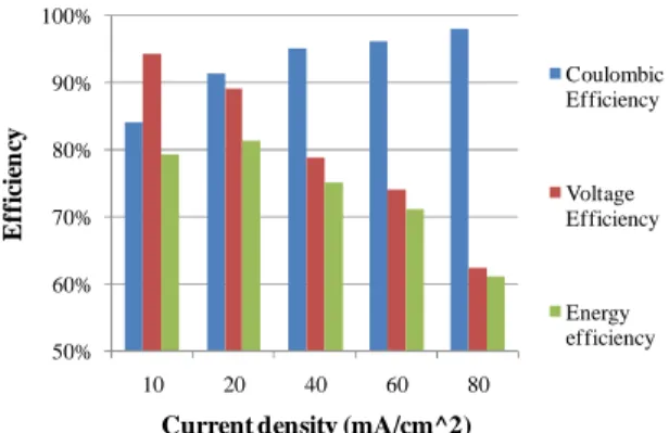
Fig. 16 - Coulombic efficiency as a function of current density and temperature for a G2 technology vanadium redox cell... 47
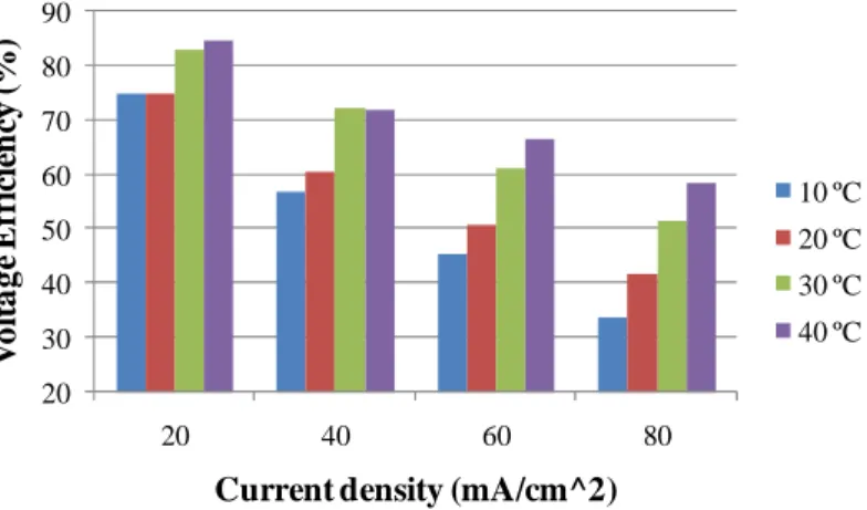
Fig. 17 - Voltage efficiency as a function of current density and temperature for a G2 technology
vanadium redox cell. ... 48
Fig. 18 - Energy efficiency as a function of current density and temperature for G2 technology vanadium redox cell. ... 48
Fig. 19- Variation of battery efficiency, discharge capacity and overall system efficiency as a function of flow rate. ... 50
Fig. 20 - Optimal charge-discharge strategy proposed by Ma et al.. ... 51
Fig. 21 - Series connection of two cells. ... 62
Fig. 22 - Comparison between the lithium ion battery of the Nissan Leaf EV and their VRFB and lead-acid battery equivalents. ... 67
Fig. 23– Typical fuel tank used in gas stations... 73
Fig. 24 - Rubber tank for VRFB liquids electrolytes. ... 74
Fig. 25 - Scheme of rubber tanks for VRFBs (a - two tanks configuration; b– four tanks configuration) inside fuel tanks with support structure. ... 75
Fig. 26 - System architecture proposed. ... 77
Fig. 27 - Evolution of the charging power output of a Nissan Leaf as monitored by Bai et al.. .... 78
Fig. 28 - Discharge process of a VRFB. ... 79
Fig. 29 - Electrical resistance as a function of the compression rate of the graphite felt electrodes of SGL GROUP. ... 81
Fig. 30 - Discharge Voltage (a) and Current (b) cycles for VRFB system. ... 82
Fig. 31 - Charge process of a VRFB. ... 83
Fig. 32 - Charge Voltage (a) and Current (b) cycles for the VRFB system. ... 84
Fig. 33 - Variation of flow rate during discharge (a) and charge (b) cycles. ... 86
xi Fig. 35 - Variation of pumping power during discharge (a) and charge (b) cycles. ... 89 Fig. 36 – Optimized Discharge (a) and Charge (b) voltage cycles proposed for the VRFB system. ... 90 Fig. 37 - Optimized Discharge (a) and Charge (b) current cycles for the VRFB system proposed. ... 91 Fig. 38– Optimized Flow rate for Discharge (a) and Charge (b) cycles for the VRFB system proposed. ... 91 Fig. 39 – Optimized Pumping power for Discharge (a) and Charge (b) cycles for the VRFB system proposed. ... 91 Fig. 40 - Efficiency comparison between1 and 2 cars charging simultaneously. ... 97 Fig. 41 - Variation of efficiency and maximum current as a function of the number of cells. ... 98 Fig. 42 - Variation of the efficiency and maximum current density as a function of membrane area. ... 99 Fig. 43 - Variation of the efficiency and maximum current (during charge) as a function of VRFB charging time. ... 99 Fig. 44 - NPV and Payback time as a function of VRFB efficiency with pumping (with 91,7% and 93,4% corresponding to the efficiency obtained by the analysis with 2 and 1 cars in simultaneous charging, respectively). ... 100 Fig. 45 – Net Present Value as a function of the Minimum Acceptable Rate of Return. ... 101 Fig. 46 - NPV and Payback time as a function of the average number of cars charged per day. ... 101 Fig. 47 - NPV and Payback time in function of percentage of system cost. ... 102
TABLE LIST
Table 1 - Comparison with various redox flow battery technologies ... 33
Table 2 - Comparison between G1 and G2 technologies. ... 49
Table 3 - Comparison between VRFBs and conventional batteries. ... 65
Table 4 – Characteristics of lead-acid batteries and VRFBs equivalent to lithium ion battery of the Nissan Leaf. ... 67
Table 5 - Compatibility of various types of rubber with sulfuric acid and vanadium oxides ... 76
Table 6 - VRFB stack components selected for the analysis. ... 80
Table 7 - Input values used to simulate the VRFB system... 81
Table 8 - Input data required for the calculation of the cash-flows of the project. ... 94
Table 9 - Cash flows of the project for the 20 years considered. ... 95
xv
NOMENCLATURE
Acronyms
VRFB Vanadium Redox Flow Batteries (G1
and G2 technologies)
RFB Redox Flow Battery
G1 All vanadium redox flow batteries
G2 Vanadium bromide redox flow
battery
ZBB Zinc/Bromine technology
ZCB Cerium/Zinc technology
PSB Polysulfide/Bromide technology
ZNB Zinc-Nickel Battery
SSFC Semi-Solid Flow Cell
SoC State of Charge
DoD Depth of discharge
EV Electric Vehicle
PHEV Plug-In Hybrid Electric Vehicles
UPS Uninterruptible power supply
GHG Greenhouse gases
ICE Internal Combustion Engine
PANI Polyaniline
THD Total Harmonic Distortion
PDVF Polyvinylidene Fluoride
GMG Graphene-Modified Graphite
GO Graphite Oxide
Tris Trishydroxymethyl aminomethane
TEOS Tetraethoxysilane
DEDMS Diethoxydimethylsilane
N-sDDs Nafion-sulfonated
diphenyldimethoxysilane
UNSW University of New South Wales
MIT Massachusetts Institute of
Technology
NASA National Aeronautics and Space
Administration
REDT Renewable Energy Dynamics
Technology Ltd.
GEFC Golden Energy Fuel Cell Co., Ltd.
Variables
η
C Coulombic efficiency-
η
E Energy efficiency-
η
V Voltage efficiency-
ηCh ChadeMo charger efficiency
-
ηAC-DC VRFB charger with an efficiency
(AC/DC)
-
η Efficiency of the VRFB without
pumping losses
-
ηtotal VRFB VRFB efficiency with pumpinglosses
-
ηsystem Overall system efficiency
-
ρ Specific mass of the liquid
electrolyte
kg/m
3P
Leaf Power consumption of the NissanLeaf during charge
kW
P
r Real discharge powerkW
P
out Power outputkW
P
in Input powerkW
Er
Real discharged energyW
E
a Available stored energyW
V
disch Voltage output of stack during dischargeV
V
chg Intput voltage of the stack duringcharge
V
OCV
disch Open circuit voltage of the stackduring discharge
V
OCV
chg Open circuit voltage duringcharge
V
R
Internal resistance ΩI
CurrentA
N
Number of cells-
E
+ Equilibrium potentialsV
E
- Equilibrium potentialsV
r
Universal constant of ideal gases 8,31447 J.mol-1.k-1T
TemperatureK
F
Faraday constant 9.64853399 x 10⁴ C.mol-1t
Times
t
chg Defined time to charge VRFBs
t
disch Defined time to discharge VRFBs
SoC
min Minimum state of charge of VRFBduring cycle
-
xvii
E
Energy density of the liquidelectrolyte
W
C
in Concentration of vanadium in thesolution before the cell
mol/L
C
out Concentration of vanadium in thesolution after the cell
mol/L
P
pump Pumping powerkW
∆
p
Total pressure lossPa
∆
p
stack Pressure loss in the StackPa
∆
p
pipe Pressure loss in the pipesPa
P
Permeability of the electrodesm
2l
Permeated specimen length ofthe electrode
m
A
cs Permeated cross section area ofthe electrodes
m
2Re
Reynolds number-
f
Coefficient of friction-
k
Coefficient of head loss-
D
Internal diameter of the pipem
Le
Equivalent piping lengthm
H
Head lossm
V
Velocity of the fluidm/s
L
Length of the sectionm
g Gravitational acceleration
m/s
2µ Dynamic viscosity
N.s/ m
2v
Cinematic viscosity of the fluidm
2/s
ε Roughness
mm
NPV
Net present value€
Pt
Payback timeyears
p
Electrical energy purchasing price€
s
Electrical energy selling price€
i
Inflation rate-
i
’ Real interest rate-
TOG
Taxes over gain-
MARR
Minimum acceptable rate ofreturn
-
A
Amortizations€
CF
Cash-Flows€
S
Gain from sales€
C
Costs associated€
Nd
Number of cars per day-
EBITDA
Earnings before interest, taxes,depreciation and amortization
€
A
r Amortization rate per year-
Inv
Investment€
RBT
Results before taxes€
Tax
Taxes€
Subscripts
chg Charge disch Discharge in Input out Output n YearUse of VRFBs to Store Energy for Fast Charging Electric Vehicles in Gas Stations
Introduction 19
1.
INTRODUCTION
1.1. MOTIVATION
Transportation sector sustainability issues
The disruptive proliferation of urban traffic along the last decades, is posing serious sustainability concerns mainly those related to urban air quality and greenhouse gases (GHG) emissions, as well as the excessive dependency of developed economies on fossil fuels. It is expected that in 2030 the transportation sector will be responsible for 55% of total oil consumption [1]. It is also expected that the population will grow 1,7 times and the number of cars even more (3,6 times) between 2000 and 2050 [2]. In this context, the current policies promoting emissions reduction and the improvement of the energy efficiency of Internal Combustion Engines (ICE) are contributing to palliate these issues [3]. Various strategies have been explored along time, such as engine downsizing achieved with turbo-charging [4], the strategy of over expansion used in several efficient hybrid powertrains [5, 6] or waste energy harvesting such as exhaust thermal energy recovery in form of Organic Rankine Cycle or Seebeck effect thermoelectric generators [7, 8].
Electric mobility
Nevertheless, the increase of the overall efficiency of conventional powertrains does not seem sufficient by itself to achieve the efficiency and emissions goals set by national and international agreements, nor does it improve the desired diversity of energy sources. Nowadays, the main alternatives to the traditional ICE are the Plug-In Hybrid Electric Vehicles (PHEVs) and the full Electric Vehicles (EV) [9]. These alternatives allow the reduction of the global fossil fuels consumption that is allocated to the traditional transports systems and are a key technology to the future smart grids [10]. Some of these alternatives are now available in the market with substantial success [11], such as Toyota Prius (PHEV) or the Nissan Leaf (EV). These vehicles are globally more efficient than ICE vehicles, mainly under urban traffic since they have no idling losses, they have good low end torque without the need for inefficient clutching, and they can recover some of the kinetic energy lost during the braking [3, 11]. In [12] a comparative environmental life cycle comparison between conventional and electric vehicles has been
Use of VRFBs to Store Energy for Fast Charging Electric Vehicles in Gas Stations
presented. As an example, using EVs, the global GHG emissions can decrease from 10% to 24% when compared with conventional diesel or gasoline vehicles. In [13] a study highlighted the EV as a means to contribute to the overall reduction of the fossil sources and energy used for transportation, although certainly this will depend on the electricity production performance. Vehicle energy storage and charging
Unfortunately, the success of PHEVs and EVs is currently hampered by some notable disadvantages, mostly related with energy storage and grid charging [14]. Their main disadvantages are their typically low autonomy (usually up to 150 km) which results from the low energy density of current battery technologies and the long time required to perform standard battery charging processes (typically, a full charge will require around 8 hours to complete) [11, 15]. The combination of these two factors is known to induce the so-called range anxiety phenomenon which, along with the high cost of batteries, is preventing the wide adoption of electric mobility [16]. A range extender unit may be added to the powertrain to prevent this, and the merits was confirmed on a Life Cycle basis, of efficiency-oriented range extenders [17], but the use of such systems increases design complexity and cost, as the price tag of some existing models incorporating range extenders indicate.
In order to minimize the aforementioned shortcomings, some EVs allow to perform the battery charging process using the fast charging mode, namely through the ChadeMo protocol [18], which displays a maximum power output of 50 kW. With this charging mode the battery of many existing models can be charged up to 80% of their State-of-Charge (SoC) in less than half an hour [19]. However, the high power output required by these chargers is especially demanding in terms of infrastructure and power grid integration. A high power consumption plan must be contracted with the electric grid service provider, representing a substantial cost even without any energy consumption. Moreover, EV charging demand will normally occur at daytime, coinciding with costly electrical peak demand periods [20].
Intermediate stationary storage
Fortunately, many of the aforementioned disadvantages of fast charging may be averted by decoupling grid consumption and the consumption due to vehicle charging by means of stationary energy storage systems. In fact, the energy needed for high power vehicle charging may be stored previously and more gradually (with lower average power) at off-peak demand
Use of VRFBs to Store Energy for Fast Charging Electric Vehicles in Gas Stations
Introduction 21
schedules than in the case of direct grid vehicle charging. This allows reducing both the contracted power consumption limit and the average cost of electricity. Also, power quality problems associated with power grid voltage, stability and frequency are minimized [21].
In this context, the present work explores the use of a specific energy storage technology to perform EV fast charging during daytime but without the energy costs associated with electric consumption during those peak demand periods. Moreover, the proposed energy storage technology could also be integrated into microgrids, to store the energy produced by nearby intermittent renewable power sources contributing to smooth their output and adapt it to power demand [22].
Both the load leveling and peak shaving processes rely on the storage of electrical energy during low demand periods releasing that energy when the electrical load is high. In peak shaving the stored energy is discharged solely to remove the load peaks, while in the case of load leveling, the aim is to stabilize the electrical load avoiding fluctuations [23].
The comparison between peak shaving and load leveling is illustrated in Fig. 1.
Fig. 1 - Comparison between peak shaving (a) and load leveling (b) (adapted from: [23]).
Typically, these two processes are implemented in low output power applications, such as domestic grids or small factories with a few kW of power. They have several advantages, the first of all being the reduction of the maximum power consumed from the power grid and consequently the reduction of the contracted power, which results in lower prices [20]. Secondly it permits a better management of the energy demanded from the power grid, taking into account the different energy prices depending of the schedule, because it is possible to buy cheaper
Use of VRFBs to Store Energy for Fast Charging Electric Vehicles in Gas Stations
power during off-peak periods, such as during nighttime [20]. Thirdly it permits a greater incorporation into the grid of energy derived from renewable sources like solar and wind, which are unpredictable sources, often with the peak power generation occurring in counter-cycle with demand. This means that the availability of an energy storage buffer will avoid wasting the energy produced during low demand periods storing it and releasing it later during high demand events. This will enable a real substitution of fossil fuel derived energy production by renewable energy sources [24, 25].
Existing stationary storage solutions
Today, reversible hydroelectric power plants are being often used since they can use the excess of energy produced by renewables (generally the wind energy produced during night hours) to pump water back to the hydroelectric dam, which creates a gravitational energy storage. However, this resource is not always available or sufficient to solve the problem and so, the integration of large scale batteries systems in the electrical power grid seems to be a good solution for complement this energy storage system.
There are several energy storage technologies that can be used for load leveling and peak shaving processes besides the pumped hydro storage. They are compressed air storage and batteries. Regarding for batteries, many groups have been studied the use of lead acid [26, 27], sodium sulfur (NaS) [23], lithium ion [28] and also redox flow batteries [29] for this applications. Flow Batteries
Many of the aforementioned systems have requirements not easily achieved for the application proposed in this work. Among the various battery technologies, the Redox Flow Batteries (RFB) have several advantages over the remainders, mainly because they have total independence between the energy capacity and rated power [30]. Other advantages of these batteries are related with their liquid nature and their storage (in tanks), which can be of any shape. In [31]the recent developments and studies of RFB concerning electrolytes, electrodes, membranes, and aqueous and non-aqueous systems have been reviewed. There are many types of RFB with various redox couples used, however, the Vanadium Redox Flow Battery (VRFB) is currently among the most studied and promising technologies of this kind. These batteries have the advantage of using the same material in both half cells. Thus, in the case of the cross mixing of the electrolytes there is no damage of the battery (as in the case of other RFBs) but only a self
Use of VRFBs to Store Energy for Fast Charging Electric Vehicles in Gas Stations
Introduction 23
discharge [32]. This is one of the main reasons for their fairly extended life even when comparing with the latest Li-ion battery chemistries. As main disadvantage, complete VRFB systems are still expensive, although the growing maturity of this technology and its attractiveness as an enabler for the wide adoption of intermittent renewable sources is likely to decrease its cost in the midterm [33-35].
Energy source shift in transportation and gas station business model
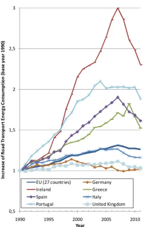
The recent economic crisis affecting several western economies was accompanied by a reduction in the demand of transportation fuel [36], this reduction is showed in Fig. 2and it can be seen that in the European Union the fuel consumption dropped by almost 4% of between 2007 and 2011. In the same period, the most pronounced reductions occurred in the Ireland and Spain which reduced around 23% and 15% respectively. Other sharp reductions can be also observed, like in Greece which reduced about 17% between 2009 and 2011 and in case of Portugal there was a sharp decline between 2010 and 2011 of about 7%.
Fig. 2 - Variation of road transport energy consumption between 1990 and 2011 in some
countries of European Union [36].
0,5 1 1,5 2 2,5 3 1990 1995 2000 2005 2010 In cr e a se o f R o a d T ra n sp o rt E n e rg y C o n su m p ti o n ( b a se y e a r 1 9 9 0 ) Year EU (27 countries) Germany Ireland Greece Spain Italy Portugal United Kingdom
Use of VRFBs to Store Energy for Fast Charging Electric Vehicles in Gas Stations
As an alternative to the costly and laborious deactivation/disposal of surplus large fuel storage tanks in gas stations, a retrofit of these deposits could be performed, adapting them for VRFB electrolyte storage and using the storage system for EV fast charging with the strategy explained before. One merit of such an approach would be to easily obtain EV fast charging spots in places which are already strategically located for vehicle traffic, optimizing otherwise wasted space and infrastructures and complementing the ICE vehicle fuel supply business with the emerging plug-in vehicle charging business in one place.
1.2.SCOPE OF THE PRESENT WORK
The present work aims to perform a preliminary project of a VRFB system installed in gas station environment taking advantage of its existing infrastructures. It is intended to store electric energy during low demand periods and use it for the fast charging of two electric vehicles simultaneously.
Given the lack of information concerning the emerging technologies involved, as well as the novelty of this topic within the UMinho research team, the present work starts with a detailed literature survey (Chapter 2), which carefully describes the operating principles of a vanadium redox flow battery, and analyzes in detail the existing VRFB technologies (G1 and G2). It provides a description of their major components, operation principles, performance, development over time, as well as the most recent developments, manufacturers and future prospects for the technology. After this, a preliminary project of the system is performed and analyzed in terms of energy efficiency, performance and economic viability, ending with a sensitivity analysis of the main parameters (Chapter 3). These two main chapters of the work have been based on two different articles submitted to the International Journal of Energy Research.
The principal motivation of the present work is based on the fact that, although the flow batteries are an emerging technology with a lack of available information in the literature, there is a real market need for such systems. This is so because there are currently no other technologies available for large scale energy storage applications displaying the same versatility and long-term reliability. On the other hand, to the author’s knowledge, this work is of a pioneering nature even in international terms and for the company Petrotec it is considered as a future business opportunity which accompanies the slow, but steady shift of the petroleum-based
Use of VRFBs to Store Energy for Fast Charging Electric Vehicles in Gas Stations
Introduction 25
automotive economy towards the electric mobility paradigm. Moreover, it takes advantage of the vast network of existing infrastructure for supplying of conventional vehicles, a network which has the advantage of being located in places of easy and fast access for vehicles.
Use of VRFBs to Store Energy for Fast Charging Electric Vehicles in Gas Stations
State of Art of Vanadium Redox Flow Batteries 27
2.
STATE OF ART OF VANADIUM REDOX FLOW BATTERIES
A battery is an electrochemical system, which is capable of storing chemical energy and generating electricity by a reaction of oxidation and reduction between two active materials.
A redox flow battery works on a principle similar to that of conventional batteries, but has the distinction of having the active materials separated from the region where electric current is generated (cell) [37]. Thus, it can be said that in a redox flow battery the active materials are not permanently sealed inside the container where electric current is produced (the cell) as in a conventional battery, but are stored separately and pumped into and across the cell according to the energy demand [32].
There are many types of redox flow batteries which can be classified by their active species, their solvent (aqueous or non-aqueous) and by the form of their active materials (liquids, solids, gaseous) [38].
There are also Hydrogen-based systems, also called “Fuel Cells” which take a fuel and an oxidant (typically hydrogen as a fuel and air as an oxidant) and produces electric energy and water [38]. However, normally a fuel cell is not considered a redox flow battery but if it could be designed in such a way that it would work in both charge and discharge directions, then a fuel cell could also be considered as a redox flow battery [38].
A typical redox flow battery incorporates two liquid electrolytes which are stored in two separate tanks (one being the positive electrolyte and the other one the negative), and they are pumped into the cell to produce energy, as depicted in Fig. 3. When the liquid electrolytes are injected into the cell (central part of Fig. 3), an electrochemical reaction (oxidation-reduction or redox) occurs, with movement of electrons along the electric circuit, as there is an exchange of ions through the membrane to maintain charge neutrality between the different ionic solutions [30].
In this chapter several types of flow battery technologies are described, and a full review of the state of art of the VRFBs is presented, including the types of VRFBs, the battery configuration, single cell configuration, the description of the circulation of the liquid electrolytes, the
Use of VRFBs to Store Energy for Fast Charging
configuration of storage tanks, the characteristics and performance, the components, and a comparison with conventional
are also presented in this chapter.
Fig. 3
2.1.TYPES OF REDOX
The first developed technology of flow ba
developed by National Aeronautics and Space Administration (NASA)
applications [39, 40]. The positive reactant of this system is an aqueous solution of ferric
(Fe2+/Fe3+) redox couple and the negative reactant is a solution of chromous
acidified with hydrochloric acid
efficiency and it was prone to crossover between iron and chromium ions
The Polysulfide/Bromide technology (PSB) was patented in 1984 by Remick been developed under the brand name Regenesys by Regenesys Technologies Ltd. owned subsidiary of RWE Innogy plc
system because both the positive and negative reactions involve neutral species, unlike a true redox system, which only involves dissolved ionic specie
exchange membranes [43-45
Use of VRFBs to Store Energy for Fast Charging Electric Vehicles in Gas Stations
configuration of storage tanks, the characteristics and performance, the components, and a comparison with conventional batteries. The typical applications and the current manufacturers are also presented in this chapter.
3 - Operating principle of a redox flow battery.
EDOX FLOW BATTERIES
The first developed technology of flow batteries was the iron/chromium (Fe/Cr) one, National Aeronautics and Space Administration (NASA) in 1970´s for photovoltaic
. The positive reactant of this system is an aqueous solution of ferric
) redox couple and the negative reactant is a solution of chromous-chromic redox couple acidified with hydrochloric acid [41]. However, this system displayed low output voltage efficiency and it was prone to crossover between iron and chromium ions [38].
ide/Bromide technology (PSB) was patented in 1984 by Remick been developed under the brand name Regenesys by Regenesys Technologies Ltd.
owned subsidiary of RWE Innogy plc [43]. However, Regenesys is not considered a truly a redox system because both the positive and negative reactions involve neutral species, unlike a true redox system, which only involves dissolved ionic species [43]. This technology uses cation
45] to separate the two liquid electrolytes in the c
Electric Vehicles in Gas Stations
configuration of storage tanks, the characteristics and performance, the components, and a batteries. The typical applications and the current manufacturers
tteries was the iron/chromium (Fe/Cr) one, in 1970´s for photovoltaic . The positive reactant of this system is an aqueous solution of ferric-ferrous chromic redox couple . However, this system displayed low output voltage and
ide/Bromide technology (PSB) was patented in 1984 by Remick [42] and has been developed under the brand name Regenesys by Regenesys Technologies Ltd. a wholly However, Regenesys is not considered a truly a redox system because both the positive and negative reactions involve neutral species, unlike a true . This technology uses cation-to separate the two liquid electrolytes in the compartments of
Use of VRFBs to Store Energy for Fast Charging Electric Vehicles in Gas Stations
State of Art of Vanadium Redox Flow Batteries 29
each cell and to provide a passage of ions to maintain electro-neutrality [44]. However, in case of rupture of the membrane in one of the cells, it will cause the mixing of both electrolytes and trigger the precipitation of sulfur [43].
The Zinc/bromine technology (ZBB) is called by Weber et al. [38] a hybrid redox flow battery because it does not store all the active material solely in liquid or gaseous form. In the ZBB technology, zinc is solid in the charged state and dissolved during the discharge, while the bromine is always dissolved in the aqueous electrolyte [43].
This technology utilizes ZnBr2 as electrolyte in both half cells [43, 46] and these two
electrolytes only differ in the concentration of elemental bromine and should have the same concentration of zinc and bromide ions at any given time during the charge/discharge cycles [43]. So, it is necessary to use an ion exchange membrane as the separator, which will allow the passage of zinc and bromide ions without allowing the passage of bromine or polybromine [43]. However, due to the high cost and low durability of the ion exchange membranes, this system generally uses nonselective micropourous membranes [43].
Comparing with other flow battery technologies, ZBB have a higher energy density, cell voltage and lower cost [47]. However, the low working current density results in a low power density (product of current density and cell voltage) [47], which means that bigger cells will have to be used for a given power output. But there are other problems with this technology, namely: bromine is highly dangerous for the environment [46], and presents problems associated with material corrosion, dendrite formation (which results in electrical shorting), high self discharge and short cycle life [38].
The Cerium/Zinc (ZCB) technology was patented by Plurion Limited Company [48] and it is described by Weber et al. [38] like a non aqueous redox flow battery, since it uses a methanesulfonic acid. This acid is used as a solvent for both electrolytes since it has conductivity comparable to hydrochloric acid but it has lower corrosion compared with sulfuric acid and it is more stable [49]. However, ZCB technology is at an early stage of development and there are still a few challenges that must be overcome [50], such as the low solubility of Cerium in methanesulfonic acid, the inefficiencies in the cerium discharge reaction in the early cycles and the increase of negative electrolyte acidity which is a result of the migration of protons from the positive electrolyte and also to the proton generation by the zinc electrodeposition [49]. An
Use of VRFBs to Store Energy for Fast Charging Electric Vehicles in Gas Stations
advantage of this technology is its high current density compared with other redox flow batteries
(successful operation of a cell at current densities as high as 400 – 500 mA/cm2 has been
claimed) [41]. Some authors reported an energy density of 12 - 20 Wh/L [51] but others have reported totally dissimilar values in the range to 37,5 – 120 Wh/L [38]. It is not clear the reasons for the differences found between the two works.
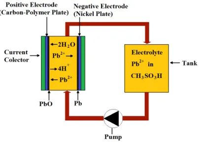
Recently single flow redox battery technologies based on lead acid batteries were proposed and studied by Pletcher et al. [52-60]. A single flow battery is different from the traditional redox flow battery because it has only a single liquid electrolyte which reacts with solid active materials, not needing an ion exchange membrane [46]. A soluble lead acid flow battery is represented in Fig. 4 and it can be seen that for a single flow redox battery system only one electrolyte tank and pump is needed. Zhang et al. [61] compared the soluble lead acid flow battery with a static lead acid battery and concluded that the soluble lead acid is more indicated for large scale energy storage systems, like a load leveling and smoothing with renewable energy systems. They also observed that the soluble lead acid exhibits a charge/discharge performance as good as a static lead acid battery and has the advantage of using methanesulfonic acid as electrolyte, which is biodegradable and environmentally friendly. However soluble lead acid batteries have disadvantages such as a lower cycle life and cell voltage.
Other single flow technologies have been proposed, such as the zinc-nickel battery (ZNB) suggested by Cheng et al. [62], which has good energy and coulombic efficiency (86% and 96% respectively, see chapter 6 for definition of coulombic efficiency) and also have high power and energy density (83 W/kg and 65 Wh/kg) when compared with other flow battery technologies [63].
The single flow acid Cu–PbO2 battery developed by Pan et al. [64] uses low cost materials
(PbO2 as the positive electrode), and shows good coulombic and energy efficiencies (97% and
83% respectively) with a cell voltage of 1,29 V.
The single flow acid Cd–chloranil battery developed by Xu et al. [65] and employs solid organic material chloranil as the positive electrode, depositional cadmium as the negative
electrode active substance and flowing H2SO4–(NH4)2SO4–CdSO4 solution as the electrolyte. This
technology offers a discharge voltage of approximately 1,0 V and coulombic and energy efficiencies of 99% and 82% respectively.
Use of VRFBs to Store Energy for Fast Charging
State of Art of Vanadium Redox Flow Batteries
Fig. 4 - A soluble lead acid technology (adapted from:
There is also a Zinc-Bromine single flow battery technology, first proposed and fabricated by Lai et al. [46] which involves a positive liquid electrolyte with a storage tank and pump system, and a semi-solid negative electrode. This technology has coulombic and energy efficiencies comparable to typical ZBB technology as well as improved energy density
More recently, a single flow zinc/polyaniline battery was proposed by Zhao et al. Polyaniline (PANI) has received much attention due to its high conductivity, low cost and good redox reversibility, making it very attractive for electrode mate
With the single flow tech
combines the high energy density of the lithium batteries with the advantages of the redox flow systems [67]. The use of a solid anode lithium metal with an aqueous cathode electrolyte was proposed by two groups independently, Goodenough et al.
Another study combining redox flow batteries with lithium batteries was made by Duduta et al. [70] from Massachusetts Institute of Technology (MIT)
redox flow battery (they called it a semi
advantages when compared to other redox flow batteries, such as higher energy density (they use suspensions of dense active materials in a liquid electrolyte) and it can operate with very low flow rates which means very low mechanical energy dissipation. They estimate that SSFC
Use of VRFBs to Store Energy for Fast Charging Electric Vehicles in Gas Stations
State of Art of Vanadium Redox Flow Batteries
A soluble lead acid technology (adapted from:[61])
omine single flow battery technology, first proposed and fabricated which involves a positive liquid electrolyte with a storage tank and pump system, solid negative electrode. This technology has coulombic and energy efficiencies arable to typical ZBB technology as well as improved energy density [46].
More recently, a single flow zinc/polyaniline battery was proposed by Zhao et al. Polyaniline (PANI) has received much attention due to its high conductivity, low cost and good redox reversibility, making it very attractive for electrode materials for use in batteries
With the single flow technology it is possible to make Li-Redox flow batteries, which combines the high energy density of the lithium batteries with the advantages of the redox flow . The use of a solid anode lithium metal with an aqueous cathode electrolyte was osed by two groups independently, Goodenough et al. [68] and Wang et al.
Another study combining redox flow batteries with lithium batteries was made by Duduta et Massachusetts Institute of Technology (MIT), who demonstrated a semi
redox flow battery (they called it a semi-solid flow cell “SSFC”). This technology has inherent ed to other redox flow batteries, such as higher energy density (they use suspensions of dense active materials in a liquid electrolyte) and it can operate with very low flow rates which means very low mechanical energy dissipation. They estimate that SSFC
Electric Vehicles in Gas Stations
31 omine single flow battery technology, first proposed and fabricated which involves a positive liquid electrolyte with a storage tank and pump system, solid negative electrode. This technology has coulombic and energy efficiencies
More recently, a single flow zinc/polyaniline battery was proposed by Zhao et al. [66]. Polyaniline (PANI) has received much attention due to its high conductivity, low cost and good
rials for use in batteries [66]. Redox flow batteries, which combines the high energy density of the lithium batteries with the advantages of the redox flow . The use of a solid anode lithium metal with an aqueous cathode electrolyte was
and Wang et al. [69].
Another study combining redox flow batteries with lithium batteries was made by Duduta et , who demonstrated a semi-solid lithium solid flow cell “SSFC”). This technology has inherent ed to other redox flow batteries, such as higher energy density (they use suspensions of dense active materials in a liquid electrolyte) and it can operate with very low flow rates which means very low mechanical energy dissipation. They estimate that SSFC
Use of VRFBs to Store Energy for Fast Charging Electric Vehicles in Gas Stations
systems could achieve energy densities of 300 - 500 Wh/L (130 – 250 Wh/kg) something which could be satisfactory to use in electric vehicles [70].
Apart from the technologies previous described, there are also the systems which are highlighted in the present work. There are two main systems, the all vanadium system (in literature this is normally called the more recent vanadium bromide system (also called G2 technology). various redox flow battery technologies is performed in
Table 1.
One promising approach to improve the energy density of the all-vanadium system is to replace the positive electrolyte with an air electrode. Such system thus becomes, properly speaking, a new type of fuel cell, called vanadium-oxygen redox fuel cell. It was firstly proposed by Kaneko et al. in 1992 and firstly evaluated by Menictas and Skyllas-Kazacos in 1997 [75]. In a recent study, Menictas and Skyllas-Kazacos [75] have built a 5-cell stack assembly and tested it for a continuous period surpassing 120 h. This study demonstrated that a vanadium-oxygen redox fuel cell stack could be successfully constructed with a significant reduction of weight and
volume. They also suggested the replacement of the sulfuric acid electrolyte by HCl or HCl/H2SO4
mixtures to improve the energy density, enabling the vanadium-oxigen fuel cells to have the triple or the quadruple of the energy density of the original all-vanadium system. However, in that study this technology was used only in fuel cell mode, which means that no recharging stage was considered. This technology might be a good solution for use in EVs in the future, since it has only one liquid electrolyte, and the regeneration (“recharging”) of the solution can be done outside of the vehicle in a separated cell optimized for charging the solution and without
weight/size limitations. This operation consists on the reduction of the V3+ ions contained in the
discharged (used) electrolyte to V2+ at the negative electrode, while producing gaseous oxygen at
Use of VRFBs to Store Energy for Fast Charging Electric Vehicles in Gas Stations
State of Art of Vanadium Redox Flow Batteries 33
Table 1 - Comparison with various redox flow battery technologies
G1 G2 ZBB ZCB Regenesys Fe/Cr Energy density (Wh/L) 20 – 33 [72] 35 - 70 [72] 50 [76] 12 – 20 [51] 37,5 – 120 [38] 20 – 30 [77] - Energy density (Wh/kg) 15 - 25 [72] 25 - 50 [72] 65 - 70 [46, 78] - 20 [78] <10 [78] Nominal Voltage 1,4 V [37] 1 V [38] 1,8 V [43] 2,1 V [79] 1,35 V [80] 1,18 V [78] Operational temperature 5 – 40 ºC [74] 0 – 50 ºC [74] 20 – 50 ºC [43] 20 - 60 ºC [49, 81] 20 – 40 ºC [77] 65 ºC (Optimal) [78] Reported energy efficiency (η) 80 – 85 % [77] 60 - 70 % at 40 ºC [72] 75 % [77] 75 % [50, 82] 60 – 65 % [43-45, 77] 70 - 80 % [78]
2.2.DESCRIPTION OF THE VARIOUS TECHNOLOGIES OF
VANADIUM REDOX FLOW BATTERIES
The use of a single metal in both half-cells was firstly proposed by N.H. Hagedorn [32], a solution which addressed the cross-contamination problem. Thus, the G1 was first patented in 1978 by Pellegri and Spaziante [71], which involves solely vanadium species in both half cells at different valence states. The G2 technology was first proposed by the University of New South Wales (UNSW) in 2001 [72] and employs a vanadium bromide solution in both half-cells [73] and
Use of VRFBs to Store Energy for Fast Charging Electric Vehicles in Gas Stations
shares all the benefits of the G1 technology, including the fact that the cross contamination is eliminated [74]. In this subchapter the operating principles of these two technologies are described.
2.2.1. All-vanadium redox flow batteries (G1 technology)
A G1 operates in an electrochemical couple based on two different reactions of vanadium ions in a dilute acid solution. This is possible because vanadium is a stable material in four
different oxidation states (V2+, V3+, V4+, V5+ ) [83].
The cathodic and anodic reactions can be represented as follows [84]: VO
2 +
+ 2H+ + e- ↔ VO2+ + H2O E° = 1,00 V
V2+ ↔ V3+ + e- E° = - 0,26 V And the overall reaction is [84]:
VO 2
+
+ 2H+ + V2+ ↔ VO2+ + H2O + V3+
The separation of the redox couples in this system is usually made using a cationic
exchange membrane, which allows the transport of H+ protons while avoiding fluid mixing. This
operation is depicted in Fig. 5 [33].
In a G1, the open circuit voltage is 1,6 V at 100 % State of Charge (SoC) and 1,4 V at 50 % SoC [84]. However there are notable obstacles in the development of cells for all-vanadium redox
battery [32]. The first obstacle is the stability of the species V4+ and V5+ in some electrolytes, e.g.,
V5+ is unstable in solutions of HCl, and V4+ is unstable in solutions of NaOH [32].
The second impediment is the solubility of compound V5+ as V
2O5 and Maria Skyllas-Kazacos and
Robert Robins discovered that the rate of dissolution of V2O5 is very slow at room temperature,
Use of VRFBs to Store Energy for Fast Charging Electric Vehicles in Gas Stations
State of Art of Vanadium Redox Flow Batteries 35
Fig. 5 - Operation of a G1 during discharge using a cation exchange membrane (adapted from:[33]).
Lather, these authors further discovered that pentavalent and tetravalent vanadium ions
are stable in electrolytes such as aqueous H2SO4 and at least 2 M pentavalent vanadium be
prepared in a solution such as 2 M H2SO4 electrolyte.
The main advantage of a G1 is that, in the event of a cross mixing between the two liquid electrolytes, the regeneration of the solution may be performed simply by recharging the fluids, unlike systems with different metals in which the mixed liquids would have to be replaced or removed and treated externally [32].
2.2.2.Vanadium bromide redox flow battery (G2
technology)
The G2 technology employs a vanadium bromide solution in both half-cells and since the
bromide/polyhalide couple has lower positive potential than the V4+/V5+ couple, the bromide ions
Use of VRFBs to Store Energy for Fast Charging Electric Vehicles in Gas Stations
The cathodic reactions of this technology are as follows [85]:
ClBr2-+ 2e - ↔ 2Br-+ Cl -or BrCl2-+ 2e - ↔ Br -+ 2Cl-
And the anodic reaction as follows [85]:
V2+ ↔ V3+ + e-
Thus, while the negative half cell utilizes the same V2+/V3+ redox couple as the G1
technology, the G2 technology uses the ClBr2-/Br- and/or BrCl2-/Cl-, or even redox couples in
reaction [85].
The G2 technology shares all the benefits of the G1 technology, mainly the fact that the cross contamination is eliminated because the same electrolyte is used in both half cells, resulting in electrolytes with virtually unlimited lifetime [74].
Other advantages of the G2 technology are the possibility of achieving concentrations of V2+
or/and V3+ ion species up to 4 M in hydrochloric acid supporting electrolyte [86]. This allows the
doubling of the energy density potential of the G1 and enables the operation of the system at broader temperatures ranges (0º C to 50 ºC), than those of G1 technology (5 ºC to 40 ºC, for 2 M of vanadium ion concentration) [74]. The extended lower temperature range is due to the higher solubility of vanadium bromide [72].
A typical electrolyte for a G2 includes 7 - 9 M HBr with 1,5 - 2 M HCl and 2 - 3 M Vanadium [72]. Furthermore, by utilizing a higher amount of bromide ions in positive electrolyte during charging, the volume of positive reservoir can be reduced by 50%. Thus, the total electrolyte volume can be reduced by 25% when compared to the G1 technology [72].
Use of VRFBs to Store Energy for Fast Charging Electric Vehicles in Gas Stations
State of Art of Vanadium Redox Flow Batteries 37
One disadvantage of the G2 technology is the risk of formation of bromine vapors during charging. Therefore, it is necessary to employ bromine complexing agents, although their high cost is a limiting factor for the commercialization of the G2 technology [73].
2.3.VANADIUM REDOX FLOW BATTERY CONFIGURATION
A vanadium redox flow cell is constituted by two half cells, each one having a solid electrode in contact with the liquid electrolyte. The separation between the half cells is made through a membrane [83], as shown in Fig. 3.
In a redox flow battery the cells are connected in series to form the cell stack, with the number of cells stacked depending on the nominal required output voltage.
In a cell stack the separation between cells is made by interposing bi-polar plates between them. Thus, a bi-polar plate is in contact with the negative electrode of one cell on one side, while on the opposite face it is in contact with the positive electrode of the next cell [83]. The constitution of a typical cell stack is shown in Fig. 6.
Fig. 6 - Constitution of a cell stack of a VRFB [83].
2.4.SINGLE CELL CONFIGURATION
Pertaining the configuration of single cells there are basically two options, one being the typical configuration with only the porous flow-through electrodes and the other including a flow channel to evenly distribute the electrolyte along the electrode [87].
Use of VRFBs to Store Energy for Fast Charging Electric Vehicles in Gas Stations
A single cell constructed by Noack et al. [88] is presented in Fig. 7, where it is possible to identify the inlet channel of the electrolyte in the flow frame (d) which enables its circulation across the porous electrode (e). It is possible to observe that the flow frame enfolds the electrode when the cell is assembled in order to ensure a perfect sealing. On the other hand, it ensures the same prescribed compression of each electrode.
Fig. 7 - VRFB test-cell constructed by Noack et al. [88]; a) Steel plate, b) Isolation plate, c) Flow-through graphite electrode, d) Flow frame, e) Graphite felt, f) Membrane, g)
Graphite electrode, h) Steel plate
However it is possible to use another configuration with a porous electrode in contact with a graphite plate in which a flow channel has been machined for electrolyte circulation, in Fig. 8 is represented a test cell made by Aaron et al. [87] which is possible to see the flow field used. In this test was demonstrated the all vanadium redox flow battery with the peak power density of
557 mW/cm2 at 60% SOC, which apparently was the highest value reported until the date of the
publication. This improvement of the energy density can reduce the quantity of material needed, which means a reduction of the cost of the system.
One way to improve the VRFB efficiency is minimize the contact resistances, so it must be used a “no gap” configuration which means that the electrodes, membranes and bi-polar plates must be in direct contact with no gap between electrode and membrane for the electrolyte flow.
Use of VRFBs to Store Energy for Fast Charging Electric Vehicles in Gas Stations
State of Art of Vanadium Redox Flow Batteries 39
In this configuration the flow into the electrode occurs due to diffusion and convection perpendicular of the flow channel [87].
Fig. 8 - Cell test made by Aaron et al. [87].
Later, Xu et al. [89] proposed a tree dimensional numerical model to study the flow channel designs for VRFBs. In this study, they considered VRFBs with no flow channel, with serpentine flow channel (Fig. 8) and with parallel flow channel designs. In this work the
maximum overall VRFB efficiency including the pumping power (ηtotal VRFB ) was obtained for VRFB
with serpentine flow channel design.
2.5.CIRCULATION OF THE LIQUID ELECTROLYTES
The US patent “Redox flow battery system and cell stack” [90] by Alberto Pellegri contains a fairly complete account on the configuration of a typical redox flow battery, so this subchapter and the subsequent one rely extensively on this publication.
The circulation of the liquid electrolytes across the cell stack can be done in two ways. A first option is to perform this circulation in parallel (represented in Fig. 9), that is, across all the cells, both towards the negative and positive electrodes, through the inlet and outlet manifolds. However, this solution might become critical when made in high voltage batteries due to the appearance of an electric current by-pass along the electrolytes contained in the manifolds. This would result in the lowering of the coulombic efficiency of the battery.
Use of VRFBs to Store Energy for Fast Charging Electric Vehicles in Gas Stations
Fig. 9 - Cell Stack in parallel mode
The second mode of electrolyte circulation is called the cascade or sequence mode. In this mode, the positive and negative electrolytes flow sequentially across all cells, flowing from the enclosure of one cell to the enclosure of the next cell, down to the last one. It seems that in this way the electric pass currents will be significantly reduced and only a residual cell-to-cell by-pass current will remain.
This solution will certainly increase the energy required for circulating the liquid electrolytes, but, apparently this increase in energy consumption will be compensated by the coulombic efficiency improvement of the electrochemical processes of charging and discharging.
There are two modes for the circulation of the liquid electrolytes in cascade, the equicurrent mode (as shown in Fig. 10a), and the countercurrent mode (as shown in Fig. 10b), patented by Pellegri and Broman [90]. In the equicurrent mode the inlet of the negative and positive electrolytes are at the same side, while the outlets of the electrolytes are located at the opposite side of the cell stack (Fig. 10a). In the countercurrent mode (Fig. 10b) the inlet of the positive electrolyte is at the same side as the outlet of the negative electrolyte, so the inlet of the positive and negative electrolytes are on opposite sides.
The countercurrent mode is more advantageous than the equicurrent mode because the operating conditions of the various cells are reasonably uniform. In other words, it allows a similar drop of electrolyte charge within each cell: the first cell located at one end of the stack works with a substantially charged negative electrolyte and with a relatively discharged positive electrolyte, while the last cell located at the opposite end of the stack works with opposite charge conditions of the two electrolytes
Use of VRFBs to Store Energy for Fast Charging
State of Art of Vanadium Redox Flow Batteries
Fig. 10 - Cell Stack in equicurre
So the magnitude of variation of the nominal cell voltage across the various cells of the stack during the cycle is reduced
phenomenon of water transfer unbalance through
the negative and positive half-cell electrolytes in each individual cell.
2.6. CONFIGURATION OF THE
For the configuration of the tanks used to store the liquid electrolyt
other the negative one and each tank has its own circulation system (pump) was named “recirculation mode”, as each electrolyte is pumped from the ta then returns back again into the same tank like is represented in
There is another possible configuration configuration works typically
negative electrolyte. The charged liquids are pumped from a tank to the stack where they are discharged, and then they are directed to another tank
from the charging phase to the discharging phase (or vice versa) the direction of the liquid reversed.
Use of VRFBs to Store Energy for Fast Charging Electric Vehicles in Gas Stations
State of Art of Vanadium Redox Flow Batteries
Cell Stack in equicurrent mode (a) and countercurrent mode (b) (adapted from
the magnitude of variation of the nominal cell voltage across the various cells of the is reduced. Another advantage is the significant reduction of the phenomenon of water transfer unbalance through the ion exchange membranes that separate
cell electrolytes in each individual cell.
CONFIGURATION OF THE STORAGE TANKS
For the configuration of the tanks, there are two possible options. Typically two tanks are e the liquid electrolytes separately, one tank storing the positive electrolyte and the
ach tank has its own circulation system (pump).
was named “recirculation mode”, as each electrolyte is pumped from the tank to the stack and then returns back again into the same tank like is represented in Fig. 3.
There is another possible configuration called the batch mode showed in
typically with four tanks, two for the positive electrolyte and two for the The charged liquids are pumped from a tank to the stack where they are discharged, and then they are directed to another tank. Therefore, in batch mode when switching from the charging phase to the discharging phase (or vice versa) the direction of the liquid
Electric Vehicles in Gas Stations
41
(adapted from [90])
the magnitude of variation of the nominal cell voltage across the various cells of the other advantage is the significant reduction of the the ion exchange membranes that separate
Typically two tanks are the positive electrolyte and the . This configuration nk to the stack and
batch mode showed in Fig. 11. This the positive electrolyte and two for the The charged liquids are pumped from a tank to the stack where they are refore, in batch mode when switching from the charging phase to the discharging phase (or vice versa) the direction of the liquid flow is
![Fig. 5 - Operation of a G1 during discharge using a cation exchange membrane (adapted from:[33])](https://thumb-eu.123doks.com/thumbv2/123dok_br/17770310.836881/37.892.277.614.128.418/fig-operation-discharge-using-cation-exchange-membrane-adapted.webp)
![Fig. 7 - VRFB test-cell constructed by Noack et al. [88]; a) Steel plate, b) Isolation plate, c) Flow-through graphite electrode, d) Flow frame, e) Graphite felt, f) Membrane, g)](https://thumb-eu.123doks.com/thumbv2/123dok_br/17770310.836881/40.892.262.632.331.638/constructed-noack-steel-isolation-graphite-electrode-graphite-membrane.webp)
![Fig. 8 - Cell test made by Aaron et al. [87].](https://thumb-eu.123doks.com/thumbv2/123dok_br/17770310.836881/41.892.172.736.188.409/fig-cell-test-aaron-et-al.webp)
![Fig. 16 - Coulombic efficiency as a function of current density and temperature for a G2 technology vanadium redox cell (adapted from: [72])](https://thumb-eu.123doks.com/thumbv2/123dok_br/17770310.836881/49.892.229.632.644.868/coulombic-efficiency-function-current-density-temperature-technology-vanadium.webp)