Filipe Alexandre Wang Liu
Computational tools for pathway optimization
towards metabolic engineering applications
Filipe Ale xandr e W ang Liu Outubro de 2013 UMinho | 20 13 Com put ational tools f or pat hw a y op timization to w ar ds me tabolic engineer ing applications
Universidade do Minho
Escola de Engenharia
Outubro de 2013
Tese de Mestrado
Mestrado em Engenharia Informática
Trabalho efectuado sob a orientação do
Professor Doutor Miguel Rocha
Professora Doutora Isabel Rocha
Filipe Alexandre Wang Liu
Computational tools for pathway optimization
towards metabolic engineering applications
Universidade do Minho
Acknowledgements
First and foremost, I would like to thank my supervisor Prof. PhD. Miguel Fran-cisco de Almeida Pereira da Rocha for the opportunity to work in this topic and for the continuous support that he provided me during the fulfillment of this work. I would like to thank Prof. PhD. Isabel Rocha from the department of biological engineering, who agreed to co-supervise my dissertation and who gave a special attention to the scientific topics more related to systems biology in particular to metabolic engineering.
A special thanks to the Bioinformatics and System Biology Interdisciplinary Ini-tiative group, were all the work was done, for their weekly group meetings that enriched my knowledge about topics concerning to systems biology, and for all the great moments of fun. I would also to like to emphasize a special thank to Paulo Vila¸ca from the group, for all the support he provided with his expertise in both computer sciences and systems biology.
I would also like to thank SilicoLife, a company that had a special interest for my work, providing me a greater motivation for this research topic.
A thank to all my friends, as without them, life would certainly be a much boring place. To Bruno Medeiros for the coffee moments, were we discuss science, politics and the meaning of life.
To my parents for their continuous effort to support my education.
Abstract
Metabolic Engineering targets the microorganism’s cellular metabolism to design new strains with an industrial purpose. Applications of these metabolic manipula-tions in Biotechnological derive from the need of enhanced production of valuable compounds. The development of in silico metabolic models proposes a quantifiable approach for the manipulation these microorganisms. In this context, constraint based modelling is one of the major approaches to predict cellular behaviour. It allows to prune the feasible space of possibilities describing possible phenotype outcomes in terms of metabolic fluxes. Under these conditions, cellular meta-bolism can be represented as an algebraic system constrained by the laws of mass balance and thermodynamics.
These systems are prone to be represented as networks, taking advantage of differ-ent graph-based paradigms, including bipartite graphs, hypergraphs and process graphs. This thesis explores these representations and underlying algorithms for metabolic network topological analysis. The main aim will be to identify potential pathways towards the optimized biochemical production of selected compounds. Related to this task, algorithms will also be designed aiming to complement net-works of specific organisms, taking as input larger metabolic databases, inserting new reactions making them able to produce a new compound of interest.
To address these problems, and also related tasks of data pre-processing and eval-uation of the solutions, a complete computational framework was developed. It integrates a number of previously proposed algorithms from distinct authors, to-gether with a number of improvements that were necessary to cope with large-scale metabolic networks. These are the result of problems identified in the previous algorithms regarding their scalability.
A case study in synthetic metabolic engineering was selected from the literature to validate the algorithms and test the capabilities of the implemented framework. It allowed to compare the performance of the implemented algorithms and validate the proposed improvements.
Keywords: Metabolic Networks; Flux Analysis; Synthetic Biology; Pathway Op-timization; Network Topological Analysis; Subgraph Extraction;
Resumo
A Engenharia Metab´olica visa a altera¸c˜ao do metabolismo celular dos
micro-organismos com vista ao desenho de novas estirpes com fins industriais. As
aplica¸c˜oes destas modifica¸c˜oes gen´eticas na Biotecnologia derivam da necessidade
de produzir de forma otimizada compostos de alto valor. O desenvolvimento de
modelos computacionais prop˜oe uma abordagem quantitativa para a manipula¸c˜ao
destes organismos. Neste contexto, a modela¸c˜ao baseada em restri¸c˜oes constitui
uma das abordagens mais usadas para a previs˜ao do comportamento celular. Esta
permite reduzir o espa¸co de solu¸c˜oes vi´aveis descrevendo o fen´otipo celular a partir
dos fluxos metab´olicos. Nestas condi¸c˜oes, o metabolismo celular pode ser
repre-sentado como um sistema alg´ebrico restringido pelas leis da conserva¸c˜ao de massa
e termodinˆamica.
Estes sistemas podem ser representados como redes, tirando partido de diferentes paradigmas baseados em grafos, incluindo os grafos bipartidos, os hipergrafos e
os grafos de processos. Esta tese explora estas representa¸c˜oes e os respetivos
algoritmos para a an´alise topol´ogica de redes metab´olicas. O objetivo principal
ser´a o de identificar potenciais vias metab´olicas para a optimiza¸c˜ao da produ¸c˜ao de
compostos selecionados. Relacionado com esta tarefa, ser˜ao desenhados algoritmos
com o objetivo de complementar redes de organismos espec´ıficos, tomando como
entradas bases de dados metab´olicas de maior dimens˜ao, inserindo novas rea¸c˜oes
de forma a torn´a-los capazes da produ¸c˜ao de novos compostos de interesse.
Para abordar estes problemas, bem como tarefas relacionadas ao n´ıvel do pr´
e-processamento e avalia¸c˜ao das solu¸c˜oes, foi desenvolvida uma plataforma
com-putacional completa. Esta integra um conjunto de algoritmos previamente pro-postos por diversos autores, em conjunto com melhorias significativas que foram
necess´arias para que estes pudessem lidar com redes metab´olicas de grande escala.
Estas melhorias resultam da identifica¸c˜ao de problemas nos algoritmos no que diz
respeito `a sua escalabilidade.
Um caso de estudo na Engenharia Metab´olica sint´etica foi selecionado da literatura
para validar os algoritmos e testar as capacidades da plataforma implementada. Este permitiu comparar o desempenho dos algoritmos implementados e validar as melhorias propostas.
Palavras-chave: Redes Metab´olicas; An´alise de Fluxo; Biologia Sint´etica;
Contents
List of Figures vii
List of Tables x
List of Acronyms xi
1 Introduction 1
1.1 Motivation . . . 2
1.2 Objectives . . . 4
1.3 Structure of the Thesis . . . 4
2 Metabolic Engineering 6 2.1 Metabolic Modelling . . . 6
2.2 Metabolic Databases . . . 7
2.3 Constraint Based Analysis . . . 9
2.4 The Synthetic Metabolic Problem . . . 10
2.4.1 Graph Based Approach . . . 12
2.4.2 Set Systems . . . 14
3 Computing Synthetic Pathways 17 3.1 Formal Definition and Data Modeling . . . 18
3.1.1 Basic Definitions . . . 18
3.1.2 Biological Entities. . . 20
3.1.3 Set Systems . . . 24
3.1.4 Conversion of biological domains to set systems . . . 26
3.2 The Subgraph Extraction Problem . . . 27
3.2.1 Solution Structures . . . 27
3.2.2 The Maximal Solution Structure. . . 30
3.2.3 Algorithms to Compute the Maximal Structure . . . 32
3.2.4 Domain Partition . . . 35
3.3 Computing Solution Structures . . . 36
3.3.1 Minimize Algorithm . . . 37
3.3.2 FindPath Algorithm . . . 38
3.3.3 Solution Structure Generation Algorithm . . . 39 iv
Contents v
3.4 Improvements to the Algorithms. . . 41
3.4.1 Minimize: Binary Search Heuristic . . . 42
3.4.2 Solution Structure Generation: Power Set . . . 45
3.5 Microorganism Selection . . . 46
4 The Biosynth Framework 48 4.1 The Framework Architecture. . . 48
4.1.1 Pre-Processing . . . 49
4.1.2 Processing . . . 50
4.1.3 Post-Processing . . . 51
4.2 Implementation Details . . . 52
4.2.1 Biosynth-Components . . . 53
4.2.2 Generic Data Models . . . 54
4.2.3 Biosynth-Data. . . 57
4.2.4 Biosynth-Algorithms . . . 59
4.2.5 Biosynth-Analysis . . . 61
4.2.5.1 Solution Feasibility Analysis . . . 62
4.2.5.2 Metabolic Model Integration . . . 62
4.2.5.3 Organism Fitting . . . 63
4.2.6 Biosynth-Core . . . 63
4.2.7 User Interface . . . 65
5 Validation of the Framework 67 5.1 The Case Study . . . 67
5.2 Pre-Processing . . . 68
5.2.1 The iMM904 Genome Scale Model . . . 69
5.2.2 Dataset Collection . . . 69
5.2.3 The Reference Pathways . . . 71
5.2.4 Data Set Analysis . . . 72
5.3 Processing . . . 72
5.3.1 Domain Analysis . . . 73
5.3.2 Pathway Extraction. . . 75
5.3.3 The Binary Search Heuristic . . . 78
5.4 Post processing . . . 79
5.4.1 Solution Feasibility Analysis . . . 80
5.4.2 Model Integration . . . 81 5.4.3 Organism Matching . . . 82 6 Conclusions 84 6.1 Contributions . . . 85 6.2 Limitations . . . 85 6.3 Future Work . . . 86
Contents vi
A Results 87
B Example Usage 88
List of Figures
2.1 Partial schema of the chemical universe of KEGG and BioCyc. . . . 8
2.2 Three possible graph representations of reactions r0, r1 and r2; a) compound graph; b) reaction graph; c) compound-reaction graph; . 12 2.3 Two set systems. a) directed hypergraph; b) process graph; . . . 15
3.1 Example directed hypergraph: V = {t0, s0, s1, s2, m0, m1, m2, m3, m4, m5, m6, m7, m8, m9, m10, m11, m12, m13, m14, m15}; E = {r0, r1, r2, r3, r4, r5, r6, r7, r8, r9, r10, r11, r12, r13, r14} . . . 28
3.2 Hypothetical synthetic problem Z = hH, S, T i, with Smin(Z) = {σ0, σ1, σ2, σ3, σ4} . . . 38
3.3 Example P-graph. . . 40
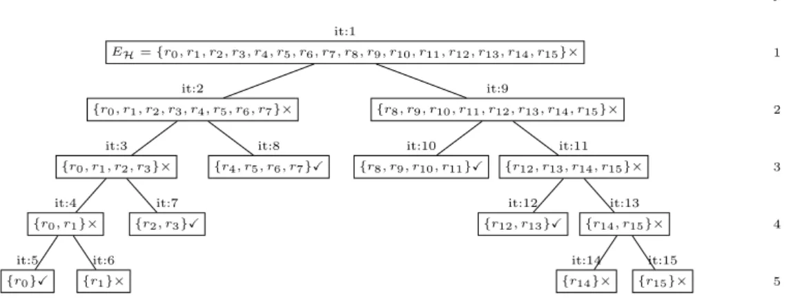
3.4 Binary Search recursion tree. × - critical set. X - discarded set. The leafs identified as critical corresponds to σ4 = {r1, r14, r15} . . . 43
3.5 Binary Search recursion tree for the extended problem with the reversible reactions. × - critical set. X - discarded set. The leafs identified as critical corresponds to σ4 = {r1, r14, r15} . . . 44
4.1 Work flow of the overall architecture . . . 49
4.2 Pre-processing layer implementation architecture. . . 49
4.3 Processing layer implementation architecture . . . 51
4.4 Post-processing layer implementation architecture . . . 52
Contents viii
4.5 BioSynth framework library diagram . . . 53
4.6 Data structures of the library biosynth-components . . . 55
4.7 Components of the data library . . . 57
4.8 Sequence diagram of the CombineSource class to extract a single reaction . . . 58
4.9 Components of the algorithmic library. . . 60
4.10 Components of the evaluator library . . . 61
5.1 Properties of the reactions for both KEGG and BioCyc datasets . . 72
5.2 Number of elements of the domain (reactions) and the hypergraph (hyperedges) model for each radius size. . . 74
5.3 The percentage of the edges (hyperarcs or operating units) accepted by the MSG and FA algorithms in the maximal structure of the first eight subdomains; ratio = number of edges in the maximal structurenumber of edges in the domain . . . 75
5.4 The solution count and the average time per solutions for the SSG and FP algorithms in both domains; Bar plot - the number of unique solution structures (in thousands) (left axis). Line plot - time per each solution structure in microseconds (right axis). SS - Solution Structure. . . 76
5.5 Solution structure σexamplegenerated by the FP algorithm (ms0, ms1 ∈
S and mt0 ∈ T ). Rectangles are substrates and products (or
byproducts). Circles represent intermediate metabolites. Each mi
is a hyperarc of the network (reactions). Solid line - main connec-tion from S to T . Dashed line - feedback loop dependency. Dotted line - alternative connection from S0 to mc, S0 ⊆ S. . . 77
5.6 Computational time per each σi in Di (i is the radius) . . . 80
5.7 The number of unique feasible flux distributions and the infeasible ratio of the previous solution sets. Left axis shows the number of flux distributions. Right axis shows the ratio of unfeasible solution structures. . . 81
Contents ix
5.8 The unique feasible solutions of the D8
BioCyc subdomain generated
by the SSG algorithm. The solutions are sorted by increasing yield of vanillin. . . 82
List of Tables
2.1 Available software tools for pathway extraction based on graphs . . 11
3.1 Recursion table for the example described in Figure 3.2. The rea-ctions are sorted as follows: EH= {r0, r2, r3, r4, r5, r6, r7, r8, r9, r10, r11, r12,
r13, r1, r14, r15} . . . 45
4.1 A brief list of supported operations of the DataEnv . . . 66
4.2 A brief list of supported operations of the EvalEnv . . . 66
5.1 Datasets sizes for both DKEGGand DBioCycmetabolic domains using
the two mechanism implemented for data collection. . . 70
5.2 Mapping of the reactions of the reference pathways with the iden-tifiers of DKEGG and DBioCyc. The (-) symbol refers to situations
where no mapping was identified. . . 71
5.3 The size of the first solution structure (σ0) obtained from Minimize 79
5.4 Top 10 organisms with highest coverage ratio. . . 83
A.1 Compounds corresponding to the verteces in the Figure 5.5 . . . 87
List of Acronyms
ACC AnalysisControlCenter
AOP Aspect-Oriented Programming
CBA Constraints Based Analysis
DCC DataControlCenter
EC Enzyme Commission number
EFM Elementary Flux Mode
EP Extreme Pathway
FA FindAll
FBA Flux Balance Analysis
FP FindPath
GSM Genome-Scale Model
JVM Java Virtual Machine
KEGG Kyoto Encyclopedia of Genes and Genomes
LP Linear Programming
ME Metabolic Engineering
MN Metabolic Network
MP Metabolic Pathway
MSG Maximal Solution Generation
SBML Systems Biology Markup Language
Chapter 1
Introduction
In the past decade, Biotechnology observed an increasing gain of popularity. One of its key advantages is the capability of de novo synthesis of secondary metabo-lites by genetic modification of microbe strains to produce high yield products
[38, 47]. These microbes are often referred as cell factories, strategically selected
microbial strains that are re-engineered to produce a target compound, offering a full catalogue of potential sustainable solutions for many modern problems. The use of cells as a factory for the production of compounds is exploited by many industries, such as pharmaceuticals, food companies, renewable energy sources,
polymers and chemicals [13, 21].
The field of Metabolic Engineering (ME) studies the optimization of living orga-nisms metabolic processes, by genetically modifying them to achieve a certain goal, such as increasing the production of a desired compound or allowing the production of a compound the wild type would not be able to produce. As such,
it plays an important role in the Biotechnology industry [12].
Technological advances in high throughput screening and Bioinformatics tools al-lowed an exponential increase of biological information, that is likely to keep in-creasing for the next years. To accommodate all this information, several large omics databases are available to store and catalog all biological data from genomes
to reactions. Such information became the core of biological research [29],
de-manding more sophisticated computational tools to analyze genome scale data sets, while manual processing became no longer viable.
Chapter 1 Introduction 2 In a traditional ME approach, industrial bioprocesses develop new strains by mul-tiple rounds of random mutagenesis. This approach usually unrolls negative side effects, such as unwanted changes that may occur in the cell metabolism. Most of these side effects are usually hard to track and diagnose.
With access to experimental data, several genome scale models of a variety of organisms were re-constructed, enabling in silico whole cell simulation of
phe-notypic responses [15, 20]. Systems Biology developed a rational design process
allowing to quantify and predict cellular responses to environmental and genetic
modifications [48]. Under a systemic scope, the phenotypic interactions are
ex-pressed as a whole system instead of individual targets, by combining information from genomics, transcriptomics, proteomics, metabolomics and fluxomics into a multi-layer system.
Metabolic Engineering is powered by computational tools and models to design new strains. These systems quantify cell phenotype expression using metabolic models, allowing to strategically develop mutant strains capable of the production of high yield bio-compounds. The process is characterized by a cycle of three main steps: design, construction and analysis, involving both systems biology and
synthetic biology [37].
The modelling of cells has been traditionally achieved through the use of dynamic models. However, these require information that is hard to gather, such as kinetic data, limiting the applicability of these models to small-scale systems. Due to the complexity in the parametrization of dynamic models, stoichiometric models are by far simpler to build. Stoichiometric models are based on the fundamental laws of mass balance, which requires only the stoichiometry of reactions,
consi-dering systems in steady state [9]. These stoichiometric models allowed the study
of the metabolism of different organisms through several methods for phenotype simulation and structural analysis.
1.1
Motivation
The re-engineering of cells for de novo synthesis of secondary metabolites involves many different steps, from data collection and curation, to optimal strain selection, pathway identification and analysis of the best solutions.
Chapter 1 Introduction 3 It is common to use computer software to aid ME processes. In the past years, a vast catalogue of Bioinformatics software was developed to fit many topics in
this field [10], ranging from network reconstruction and representation problems
to data visualization and metabolic network analysis. Despite of this effort, most topics still present a big challenge to software development, since the reconstruc-tion, analysis and optimization of large scale metabolic networks still face many challenges.
Advanced computational tools are currently able to identify optimal pathways through stoichiometric network analysis by either computing algebraically steady states of the stoichiometric network or from graph topological analysis. The com-putation of steady states relies in the analysis of the feasible solutions cone which
represents all possible steady state flux distributions. Extreme Pathways (EP) [4]
and Elementary Flux Modes (EFM) [55] both compute flux vectors through
con-vex analysis [17]. However, these methods scale poorly and are inefficient for large
scale networks. Several attempts have been made to adapt both EP and EFM to large scale data sets, either by taking advantage of modern multi-core processors
[58] or using stochastic heuristics [44]. However, due to the exponential growth
of combinatorial possibilities, for large scale systems, convex analysis still suffers from many pitfalls from memory problems to computational time.
An alternative approach is searching pathways with graph topology algorithms, based on graph search algorithms with extra rules that meet the criteria of a metabolic context. Graph traversals are fast and many algorithms were adapted to ME problems. However, graph searching for optimal solutions suffers equally from complexity issues, although for a single solution they are much faster compared to
convex analysis methods [6].
Metabolic Engineering is powered by in silico analysis and, therefore, there is a demand for specialized integrated development environments, that still offers a challenge for software engineers. Most tools are developed as standalone programs or web services, making difficult the integration and analysis of results and most time is spent on writing computer scripts to parse the input and output of tools, which is not productive and it is not practical. Therefore, commercial applications such as MatLab, designed for numerical computing, are by far the most popular in
the area [27] and there are only a few specialized open-source platforms available.
OptFlux [52] is one of those platforms for in silico ME, integrating many
Chapter 1 Introduction 4 development of plug-ins to integrate within the platform, thus allowing its easy extension.
1.2
Objectives
Given the context described above, the main aim of this work will be the deve-lopment of computational tools for the optimization of pathways over a metabolic network, given specific design objectives under the realm of Metabolic Engineer-ing applications. More specifically, the work will address the followEngineer-ing scientific/ technological goals:
1. To build metabolic networks using graph-based representations, integrating distinct data sources including metabolic databases (e.g. KEGG or Meta-Cyc) or metabolic models, allowing flexible user defined filters to be applied and contemplating information related to the metabolic capabilities of each organism of interest.
2. To design and implement optimization algorithms that allow searching over these metabolic networks for the best routes from sets of source metabo-lites to target metabometabo-lites, given the specificities of the underlying graph representation and being able to optimize these paths according to different criteria.
3. To design and implement methods to evaluate the generated solutions, for the problems in 2.
4. To integrate the algorithms implemented into a computational framework, which is able to set up the entire process of computing synthetic ME path-ways.
5. To validate the proposed algorithms with a selected case study from litera-ture.
1.3
Structure of the Thesis
The document is divided in six chapters. In this first chapter, we provided a brief introduction of the motivation and the main aims of the work.
Chapter 1 Introduction 5 The second chapter, Metabolic Engineering, introduces several important aspects related to computational tools for metabolic modelling and optimization methods, as well as the introduction of the synthetic pathway extraction problems and the state of art of the available methods and algorithms for solving of it.
The third chapter, Computing Synthetic Pathways, presents a unified formal defi-nition of several selected pathway extraction algorithms and the underlying graph representations. A detailed analysis of each of these algorithms is made to under-line their weakness and strengths.
The fourth chapter, The Biosynth Framework, describes the framework design and implementation details, developed in this work to address the synthesis problem. The fifth chapter, Validation of the Framework, applies the tools to a case study from the literature, to benchmark the developed framework by comparing the obtained results with the available solutions.
Finally the last chapter, Conclusions, presents the main conclusions of the work, also proposing future research topics.
Chapter 2
Metabolic Engineering
Metabolic engineering (ME) proposes a rational strategy to analyze and optimize cellular metabolic systems, recurring to mathematical models to quantify changes in the system. A metabolic system is a set of interconnected complex circuits of reactions and metabolites known as metabolic networks (MN).
Manipulation of such networks is usually a complex task, and quite impossible by na¨ıve selection of biological entities. Indeed, it is nearly impossible to find the best combination of genes to express towards a desired phenotype outcome without resorting to computational tools. The analysis of MNs mainly relies on in silico modelling and computer algorithms to analyse and quantitatively simulate such networks.
2.1
Metabolic Modelling
Every cell conducts metabolism through a series of interconnected pathways, where a metabolic pathway (MP) can be defined as a coherent set of reactions that together conduct a primary metabolic function. A pathway typically converts a primary substrate (or several) to a target product through a combination of reactions. Another important aspect of a MP is that it should be feasible and observable, otherwise there would be little interest in defining it, as it would be
inapplicable in real situations [57].
A metabolic model consists of a network of chemical reactions that allows to predict the behaviour (or limitations) of cellular micro-organisms. These models
Chapter 2 Metabolic Engineering 7 can be targeted to a specific pathway, such as the central carbon metabolism, or integrate multiple subsystems to assemble genome scale models (GSM). The GSM allows interaction between subsystems, which increases the capability of phenotype prediction in different scenarios. These models are validated with experimental data to check whether the models correctly predict the desired outcomes. The reconstruction of GSMs is usually a cyclic process involving multiple rounds of validation and model tuning.
The basic elements required to describe a metabolic system are:
• A set of compartments (where reactions take place);
• Metabolites in the system. Since a metabolite can be present in different compartments and they are non-interchangeable, a single metabolite (e.g., water) can have multiple species (e.g., water a, water b, water c) spread in distinct compartments;
• Chemical reactions that are able to transform metabolites inside a compart-ment or transfer metabolites between different compartcompart-ments;
• Other features that are not relevant for this work: including genes and gene-reaction rules.
The analysis of GSMs is typically done with computer tools and algorithms. The Systems Biology Markup Language (SBML) is a free, open, XML based format
for encoding metabolic models [28], that is one of most popular computer readable
formats.
2.2
Metabolic Databases
Most in silico tools rely on the information available in biological databases. This is no exception for ME, as the reconstruction of GSMs involves the use of a lot of information from different public databases. There are several bioinformatics resources available in the web for metabolic pathways. The Kyoto Encyclopedia
of Genes and Genomes (KEGG) [31, 32] is one of the main resources,
Chapter 2 Metabolic Engineering 8 set of entities of interest is the chemical universe mainly composed of metabo-lites (compounds) and chemical reactions. KEGG features four database (i.e., Compounds, Glycans, Reactions and Enzymes) to assemble biochemical
informa-tion (Fig. 2.1(a)). The compound database hosts chemical compounds, while the
Glycan database contains only carbohydrates structures, making the metabolite databases. The reaction database assembles chemical reactions, where each rea-ction contains a set of products and reactants from either of the metabolite types (i.e., compound or glycan). Finally, the enzyme database links reactions to genes, which serves as a gateway to the external resources.
KEGG offers a simple but accurate representation of cellular metabolic
path-ways. However, other databases such as the BioCyc [34] database consortium,
contain several metabolic pathway databases with a much more complex entity relationship. While, in KEGG, only four entities assemble the universe of chemi-cal reactions, the BioCyc schema represents the chemichemi-cal universe of the metabo-lite components separating into basic compounds, RNA and proteins. Then, the
association of reactions to enzymes is more complex (Fig. 2.1(b)).
Metabolite Reaction Enzyme Organism Compound Glycan is a is a catalyzes enzyme left, right appears (a) Reaction Metabolite
Protein Compound RNA
Enzymatic Reaction Enzyme Organism catalyzes enzyme is a reaction enzymatic reaction is a is a is a appears left, right (b)
Figure 2.1: Partial schema of the chemical universe of KEGG and BioCyc.
The BioCyc database consortium contains several databases, each specific for a certain organism. The databases are separated in three tiers. The first tier con-sists of databases that have gone though multiple persons-years of heavy manual curation, while in the second tier records are also under curation but with less
Chapter 2 Metabolic Engineering 9 effort. The last tier contains automatically generated databases from the BioCyc
Pathway Tools [35, 36], with no curation effort. In the BioCyc consortium, the
MetaCyc database (first tier) [7] is the only generic knowledge base containing
information on multiple organisms.
The KEGG and BioCyc are the two major knowledge bases for metabolic infor-mation, nevertheless each of them presents a noticeable growth rate of information
each year. There are several more metabolic databases such as Model SEED [2]
and BiGG [54], but these are relatively small compared to the previous mentioned
databases [33]. To complement these pathway databases, there are some more
specific databases. For instance, BRENDA focuses on enzymatic reactions having
more than 79 000 individual reactions from 10 500 organisms. The ExplorEnz [45]
and ENZYME [3] are specific for enzyme and enzyme-catalyzed reactions
descrip-tion classified by the Enzyme Commission number (EC) a numerical classificadescrip-tion scheme to classify enzymes by function.
The heterogeneity of the data information sources offers a rich set of metabolic information. However, without a standard representation, this provides a huge amount of redundant data. Most of these databases have cross references to each other for part of their records, but still there are many cases of inconsistency between these.
2.3
Constraint Based Analysis
Constraint Based Analysis (CBA) is one of most popular approaches adopted for in silico analysis of MNs. This approach differs from other traditional alternatives since it has not been limited by the availability of kinetic information, thus allowing the analysis of genome scale models capturing whole cell information. In CBA, the system is subject to several constraints, such as the laws of mass balance and thermodynamics. The system is constrained to the stoichiometric information,
the reactions reversibility and the maximum flux allowed in each reaction [16]. It
is, thus, possible to determine the feasible space, which allows to understand the capabilities of the system under these circumstances.
Flux Balance Analysis (FBA) uses an optimization approach to, over this
feasi-ble space, calculate the optimal flux distribution of a steady state network [42],
Chapter 2 Metabolic Engineering 10 optimally assign fluxes to reactions in a MN based on an objective function using a linear programming (LP) formulation. A limitation of FBA is that it only re-turns one optimal solution, as for a given MN, in some scenarios, there may exist multiple optimal flux distributions.
There are several other CBA methods, including variants of FBA, that will not be mentioned as these are not relevant to this work. Those are applied, for instance,
when simulating the effects of gene knockouts or flux variations on a GSM [60].
2.4
The Synthetic Metabolic Problem
A synthetic (or retrosynthetic) ME problem can be summarized as the following: given a well defined GSM, the goal is to find a set of reactions that attached to the model would augment its capability to produce new compounds of interest, which are non native to the organism.
This can be viewed as a reverse optimization process. While, in ME, for the optimization of a MN using stoichiometric models, the objective function and all participating reactions are known and well defined, in a synthetic problem for de novo synthesis of a target compound, the problem is to find a set of reactions that are compatible with the host taken from a larger knowledge base of chemical reactions.
The synthetic problem starts with the selection of a target compound and a host organism, represented by a metabolic network, which is set as the chassis. Pathway extraction algorithms identify candidate reactions from a known domain that, if introduced to the chassis, allow to augment the capability of the organism to produce the target compound. A less traditional problem would be to optimize the selection of the chassis itself. In this scenario, the chassis is unknown, therefore the pathway extraction algorithms have to find the best pathway out of the entire domain.
The identification of optimal stoichiometrically balanced pathways is often prob-lematic and offers many challenges. The number of combinatorial possibilities exponentially increases with the size of the search domain. Another important factor is the definition of what is an optimal MP. Depending on the criteria and
Chapter 2 Metabolic Engineering 11 complexity, one could argue that an optimal MP would be the solution that re-turns the highest production yield with the minimum amount of reactions, but equally valid criteria may be defined.
There are several methods for pathway extraction from MN, that can be subdi-vided into two main categories: steady state analysis or graph topological analysis. Extreme pathways (EP) and elementary flux modes (EFM) compute non decom-posable minimal pathways from metabolic networks. A non decomdecom-posable minimal pathway is a minimal set of reactions that satisfies the steady state condition and that is non reducible, i.e., the removal of any reaction from this set invalidates the steady state condition.
EPs and EFMs can be used to analyze network robustness [64]. Since the amount
of EFM and EP usually increases exponentially with the size of the network, it is impossible to compute them in most of the GSMs due to computational
intractability. Because these methods are unable to analyse large GSMs, the
computation of database size networks such as the KEGG or BioCyc is definitely out of their reach.
An alternative approach is to rely on topological analysis of metabolic networks, which offers a faster approach to identify potential MPs. There are several
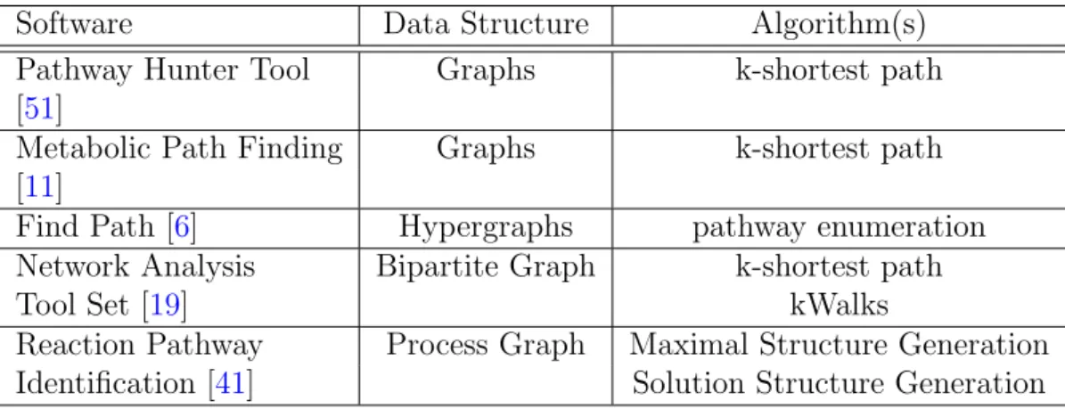
im-plementations based on a variety of graph structures and algorithms (Table 2.1).
Some of those are more generic, to be able to search any network such as protein-protein interaction networks, others are designed specifically for metabolic net-works.
Table 2.1: Available software tools for pathway extraction based on graphs
Software Data Structure Algorithm(s)
Pathway Hunter Tool Graphs k-shortest path
[51]
Metabolic Path Finding Graphs k-shortest path
[11]
Find Path [6] Hypergraphs pathway enumeration
Network Analysis Bipartite Graph k-shortest path
Tool Set [19] kWalks
Reaction Pathway Process Graph Maximal Structure Generation
Chapter 2 Metabolic Engineering 12 In the next section, several metabolic network models and analysis methods are described.
2.4.1
Graph Based Approach
A graph is a common mathematical model to define relationships between entities. In the metabolic network context, there are two participating entities in the net-work: metabolites and reactions. Since graphs have only a single type of vertex, there are several alternative types of graph models.
r0: ATP + L-Glutamate
2.7.2.11
−−−−→ ADP + L-Glutamyl 5-phosphate
r1: Acetyl-CoA + L-Glutamate 2.3.1.1 −−−→ CoA + N-Acetyl-L-glutamate r2: ATP + N-Acetyl-L-glutamate 2.7.2.8 −−−→ ADP + N-Acetyl-L-glutamate 5-phosphate ATP ADP L-Glutamyl 5-phosphate L-Glutamate N-Acetyl-L-glutamate N-Acetyl-L-glutamate 5-phosphate Acetyl-CoA CoA (a) 2.3.1.1 2.7.2.8 2.7.2.11 (b) 2.3.1.1 2.7.2.8 2.7.2.11 ATP ADP L-Glutamyl 5-phosphate L-Glutamate
N-Acetyl-L-glutamate N-Acetyl-L-glutamate 5-phosphate Acetyl-CoA
CoA
(c)
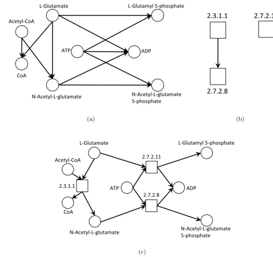
Figure 2.2: Three possible graph representations of reactions r0, r1 and r2; a)
Chapter 2 Metabolic Engineering 13
The compound graphs (Fig. 2.2(a)) allow the analysis of several topological
pro-perties, such as connectivity, length, or cluster density, among others [43]. In a
compound graph, a link between compounds a and b means there is a reaction that requires a in order to get b, but since a reaction may require more than one sub-strate, a single reaction can spawn many edges between substrates and products.
The dual of this model are reaction graphs (Fig. 2.2(b)), where an edge between
two vertices (that are reactions), captures the property of the dependency. As an
example, in Figure2.2(b), the reaction 2.7.2.8 is dependent on the products of the
reaction 2.3.1.1, and therefore, they are related. The combination of both com-pounds and reactions into a single graph model generates a bipartite graph (Fig.
2.2(c)), having two disjoint sets of vertices of compounds and reactions, where an edge between a compound and a reaction represents substrates, and the opposite represents products.
Graph topological analysis uses well known graph based traversal algorithms, most of them derived from a Breadth-first or Depth-first search approach. The main advantage of graph methods is the computation time of a single solution, which in most cases is achieved in polynomial time, and the availability of many well defined algorithms for graph analysis.
A common strategy to identify a possible optimal route between a substrate s and a product t is to use shortest path algorithms. However, since there is a possibility to have multiple variants between two vertices, it is common to use algorithms that enumerate k multiple alternative paths, such as the k-shortest
path algorithm [19, 51].
Traditional graph algorithms suffer from two major pitfalls. It is possible for some pathways not to be linear, i.e., they do not correspond to a linear path between s and t. A path in a graph model is always a sequence of edges between s and t. This usually does not express exactly a pathway, but a portion of what could be the pathway, as most pathways fork into multiple routes because of multiple dependencies. Therefore, computing exact pathways from paths in graphs is a complex task, which requires merging multiple solutions.
Another problem is due to the fact that MNs are usually small world networks, where most nodes can be reached by a small number of hops from any other node
Chapter 2 Metabolic Engineering 14 usually serve as central hubs connecting to most of reactions. This will, eventually,
mislead the path finding algorithms to generate non relevant paths [11,53].
Several alternatives are proposed to fix this issue. By weighting the graph edges by their degree, in shortest path algorithms, this allows to penalize hub compounds. However, this is still inaccurate as the degree is very dependent on the sample of the network. Also, several non-cofactor compounds have a relative high degree (e.g., pyruvate). Other authors propose more sophisticated strategies by using
the annotated data, such as the KEGG reaction pair annotation [39], where each
compound to compound pair has an special annotation that describes whether they are the main link or a cofactor link. This allows a more advanced filtering of
the cofactors [18, 65]. Nonetheless, false positives and negatives still occur due to
flaws in the data and by improper or incomplete characterization.
2.4.2
Set Systems
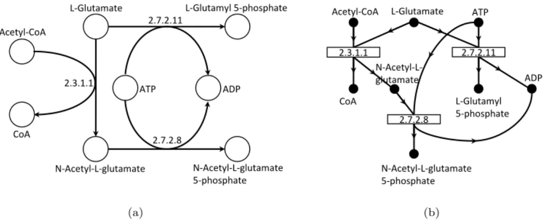
The ambiguity of graph models and the incapability of those to define multi depen-dency relationships demanded a different model to represent metabolic networks. Both hypergraphs and process graphs have been put forward for that purpose. They are very closely related as they are both set systems, so unlike graphs, where each edge connects single entities, in set systems, an edge establishes a connection between two sets.
A directed hypergraph is a graph where each edge may contain multiple source
vertices (head) to multiple destination vertices (tail) (Fig. 2.3(a)). This edge is
denoted as hyperedge for undirected edges and hyperarc for directed edges. This type of graph was introduced to model database schemas, being first described as functional dependency graphs because of the importance of their closure properties
[1]. Later, it gained application in other fields, being one of them chemical reaction
modelling [59].
A process graph is very similar to an hypergraph and a bipartite graph. This model was designed to represent chemical synthesis problems, as common graphs
were unable to define properly these systems [23]. They are similar to bipartite
graphs because the number of edges is equal to a compounds-reaction graph (Fig.
2.3(b)). However, the relationship between these edges is ambiguous as a single edge between a compound and a reaction has little meaning. The process graph
Chapter 2 Metabolic Engineering 15 2.7.2.11 ATP ADP L-Glutamyl 5-phosphate L-Glutamate 2.7.2.8 N-Acetyl-L-glutamate N-Acetyl-L-glutamate 5-phosphate Acetyl-CoA 2.3.1.1 CoA (a) L-Glutamyl 5-phosphate L-Glutamate Acetyl-CoA ATP 2.7.2.8 N-Acetyl-L-glutamate CoA ADP N-Acetyl-L-glutamate 5-phosphate 2.7.2.11 2.3.1.1 (b)
Figure 2.3: Two set systems. a) directed hypergraph; b) process graph;
uses operational units to define relationships between compounds, in a way that is similar to an hyperarc since each operational unit connects two disjoint sets of vertices. For the sake of simplicity, operational units will be called hyperarcs as they share the same properties.
In set systems, there is no exact notion of what exactly defines a path (or hy-perpath) between two vertices. This definition varies depending on the problem context. For the metabolic context, a hyperpath S −T between two sets of vertices S and T can be defined as: from an initial set of vertices denoted as substrates (S) to another set of vertices denoted as products (T ), a hyperpath is a set of hyperarcs that can be satisfied by the initial set S, and satisfy the set T . In a dependency problem, a hyperarc needs to be satisfied by a set of vertices, and sat-isfies another set of vertices. The head of the hyperarc are the vertices that need to be satisfied, while the tail contains the dependencies that a hyperarc satisfies, when included in a system.
Mathematically, the objective is to compute, from a set of reactions denoted as the reaction universe, a subset that satisfies a certain set of constraints:
• The metabolites that are unsatisfied must belong to the set of substrates vertices S;
• All the products in T must be present in the subset;
• Every reaction in the subset must be connected to at least one product in T .
Chapter 2 Metabolic Engineering 16 This problem can be viewed as a subgraph extraction problem, in which given a large set system which contains all possible reactions, the goal is to find com-binations that satisfy S − T . The big advantage, when compared to traditional graph methods, is that it is now possible to obtain combinations of reactions that actually assemble the exact shape of the pathways. Because the paths are multi-dimensional, such that they do not always assemble a linear sequence of several edges, it is not possible to determine what is an optimal hyperpath between S and T . Thus, the algorithms relies on enumerating all possible hyperpaths from S to T .
There are several algorithms related to these models. The first category includes
algorithms to prune the network [24]. Since this is a combinatorial problem, one
question to address is to determine which building blocks (i.e., all the reactions that are available to assemble the pathways) are necessary. In a set of reactions, there may be several elements that can be discarded since they do not participate in any pathway due to compatibilities (e.g., a reaction that is unsatisfiable). Removing these reactions would reduce the size of the elements of the set, which in turn would reduce the complexity of the problem.
The other category are the algorithms to generate the hyperpaths that satisfy S−T
from a given set of reactions. The FindPath algorithm [6] allows to enumerate all
minimal solutions from an hypergraph, while the Solution Structure Generation
algorithm [25] computes all possible combinations of pathways from a process
graph.
In the next chapter, a formal definition is introduced to describe and analyze the synthesis problem and the algorithms mentioned above. The set systems offer a potential solution to the synthetic ME problem. Therefore, the main focus of this work is to apply these algorithms to extract pathways from database networks (i.e, KEGG and BioCyc). However, they have their own drawbacks, which are analyzed in deeper detail in the following chapter.
Chapter 3
Computing Synthetic Pathways
In the previous chapter, several state of the art graph representations and algo-rithms to compute pathways from metabolic networks were introduced. Extreme Pathways (EP) and Elementary Flux Modes (EFMs) are both precise methods to generate pathways, but they are limited by the size of the networks, since up to date it is still impossible to apply these methods over Genome-Scale Models (GSMs). Therefore, the application of these methods to database size networks, which are many times larger than GSMs, is definitely inappropriate.
The graph topological analysis methods are more convenient to extract pathways from database size networks, as there are many cases of success applications of graph path searching algorithms to infer pathways. A major problem of these methods is the accuracy of the results. A solution is to apply set systems to model chemical networks, since these show more similarity to the structure of the network.
In this chapter, the synthetic Metabolic Engineering (ME) problem, the sets sys-tems and related algorithms are introduced in a formal notation to precisely ana-lyze several aspects related to their behavior, including aspects such as the com-plexity and precision of the algorithms, as well as other limitations.
Chapter 3 Computing Synthetic Pathways 18
3.1
Formal Definition and Data Modeling
3.1.1
Basic Definitions
To describe the algorithms and their properties, a notation is specified to represent the entities, special sets and functions that participate in a synthesis problem. Most of the notation follows the definitions and theorems defined by the process
synthesis algorithms [23–25]:
Zero ∅ Empty set
Calligraphy typing M, R, D, Z, S, H, P Special Sets
Capital letters M, R, S Sets
Lowercase letters m, r, e, o Single entities
If not stated otherwise, all sets defined in this chapter are assumed as unordered sets, such that two sets containing {1, 2} and {2, 1}, are considered as equal. Ordered sets will be explicitly presented, being defined by hi brackets. As an example, a tuple defined by ha, bi is an ordered pair of two elements, such that ha, bi is not equal to hb, ai. Similarly, a triple is written as ha, b, ci.
The basic set operations are presented in this section with minimal detail, as these have the same definition as in most set problems. These operations are the following:
• Element relation: a is said to be an element of a set M , written a ∈ M , if
M contains a (for the opposite relation the symbol /∈ refers to ”is not an
element of”);
• Inclusion relation: a set A is said to be a subset of B, written A ⊆ B, if B contains A (for the opposite relation the symbol * refers to ”is not a subset of”);
• Proper Subset: a set A is said to be a proper subset of B, written A ( B, if B contains A, but A does not contain B (i.e., B contains A but the sets are not equal);
• Union operation: the union of two sets A and B is defined by {x : x ∈ A or x ∈ B}, written as A ∪ B;
Chapter 3 Computing Synthetic Pathways 19 • Intersection operation: the intersection of two sets A and B is defined by
{x : x ∈ A and x ∈ B}, written as A ∩ B;
• Set Difference operation: the set difference of sets A and B is defined by
{x : x ∈ A and x /∈ B}, written as A\B;
• Size of a set: the size of a set A is defined by the function |A|, that counts the number of elements in A;
• Power Set: the power set of a set A is defined by the function ℘(A) = {X : X ⊆ A}, which is the set of all subsets of A;
• Cartesian product: the Cartesian product of two sets A and B, is denoted by A × B, being defined as: {ha, bi : a ∈ A and b ∈ B}
For ordered sets, the πi(X) functions return the i-th element of an ordered set.
As an example, π1(ha, bi) = a while π3(ha, b, ci) = c.
Several useful definitions are given next, being used in further sections. Definition 1. (Findable)
An element a is said to be findable in A, written as a ˙∈ A, if and only if, the
following occurs:
1. A is a set, and a ∈ A verifies;
2. A is an ordered set of n elements, and at least one of a ˙∈ πi(A), where
1 ≤ i ≤ n, is true.
Definition 2. (Included)
A set A is said to be included in B, written as A ˙⊆ B, if and only if, for each
element a ∈ A, then a ˙∈ B must be true.
The definitions1and2allows to later simplify complex operations of element and
set inclusion, that otherwise would require a lot of recursive πi operations to find
elements in tuples that may be nested inside of set of tuples. Other symbols are introduced later in their corresponding sections.
Chapter 3 Computing Synthetic Pathways 20 In the next sections, two levels of entities and models will be presented: the biolo-gical level, which includes entities that are the main building blocks of the meta-bolic system, followed by their mathematical models, which are created from their biological counterparts, being the ones used by the algorithms that are analyzed in this chapter.
3.1.2
Biological Entities
Here, biological entities are defined as those representing biochemical components within metabolic networks, namely reactions and metabolites. Each of the entities contains a minimal set of characteristics used to capture the properties required to compute the metabolic synthetic problem.
A metabolite is a single entity that, in general, is defined by the symbol m (al-though later the symbols s and t will also be use to define metabolites to easily distinguish supply and target metabolites). The universal set of metabolites M is a finite set that contains all distinct metabolites of a system. The following example is a valid universal set:
Me.g. = {m0, m1, m2, m3, mPyruvate, m2-Acetolactate, mV T, mO2, mCO2, mH2O}
There are many attributes that could be assigned to a metabolite entity, like the chemical formula, but for the purpose of the pathway extraction algorithms, at this stage, these can be discarded.
A reaction entity r defines a relationship between metabolites, as follows: Definition 3. (Reaction)
A reaction r is an ordered pair of two sets of metabolite-stoichiometry pairs α and
β. Since a metabolite-stoichiometry pair is a tuple hm, ni ∈ M × R+, a reaction
r can be defined as:
Chapter 3 Computing Synthetic Pathways 21 The symbol r without superscript notation usually represents a reversible reaction,
where r can either assume hα, βi or hβ, αi, which is equivalent to the ←→r notation.
If the arrow on top has a single direction this indicates that r is irreversible. The direction of the arrow corresponds to the orientation of the reaction (e.g., if
r = hα, βi then −→r = hα, βi and ←−r = hβ, αi). Similarly to M, the universal set of
reactions is written by the symbol R, which is a finite set that contains all reaction entities in a system. The following reaction:
m2-Acetolactate+ mCO2
r0
2 mPyruvate
would be represented by:
r0 = h{hm2-Acetolactate, 1i, hmCO2, 1i}, {hmPyruvate, 2i}i
and would be an element of the following hypothetical universal set of reactions:
Re.g. = {r0, ←r−1, r2, r3}
A reaction riis identified by the subscript i, and any universal set may only contain
one version of ri (i.e., R0e.g. = {r0, ←r−0, r1} would not be a valid universal set).
The functions Ψ− and Ψ+ map reactions to metabolites. These metabolites are
denoted as reactants (or substrates) and products of the reactions. Definition 4. (Reactants)
The mapping of a single reaction to the set of its reactants is defined by the
function Ψ0−, while the mapping of the reactants of a reaction set is defined by
the function Ψ−. There are given by the following expressions:
Ψ0−: R → ℘(M) Ψ0−(r) = [ p ∈ π1(r) π1(p) Ψ−: ℘(R) → ℘(M) Ψ−(R) = [ r ∈ R Ψ0−(r)
Chapter 3 Computing Synthetic Pathways 22 Definition 5. (Products)
On the other hand, the mapping of a single reaction to the set of its products is
defined by Ψ0+, while the correspondent mapping of the products of a reaction set
is defined by the function Ψ+, as follows:
Ψ0+: R → ℘(M) Ψ0+(r) = [ p ∈ π2(r) π1(p) Ψ+: ℘(R) → ℘(M) Ψ+(R) = [ r ∈ R Ψ0+(r)
The function Ψ− returns the set of all metabolites that participate as a reactant
(or substrates) in the set of reactions R, while the function Ψ+ returns the set
of all metabolites that are products of R. The function Ψ with no superscript returns the entire set of metabolites that participate in a set of reactions, which
is equivalent to Ψ(R) = Ψ−(R) ∪ Ψ+(R).
The reverse functions are defined as consumers and producers of a metabolite set M , mapping metabolites to reactions.
Definition 6. (Producers)
The set of producers of a metabolite set is defined by the function ϕ−.
ϕ−: ℘(M) × ℘(R) → ℘(R)
ϕ−(M, R) = [
m ∈ M
Chapter 3 Computing Synthetic Pathways 23 Definition 7. (Consumers)
The set of consumers of a metabolite set is defined by the function ϕ+:
ϕ+: ℘(M) × ℘(R) → ℘(R)
ϕ+(M, R) = [
m ∈ M
{r : r ∈ R | m ˙∈ π1(r)}
Because metabolites do not contain information about reactions, the ϕ functions require a set of reactions as a parameter. The ϕ is usually applied on the universal set of reactions, to identify all reactions related to a set of metabolites. In some cases, to simplify the notation, ϕ(M, R) will be considered equivalent to ϕ(M ), assuming the omission of the reaction set parameter to correspond to the universal set of reactions.
Similar to the Ψ function, the ϕ without superscript is a function that returns all reactions in R, such that the metabolites in M participate either as a substrate
or a product. This is equivalent to ϕ(hM, Ri) = ϕ−(hM, Ri) ∪ ϕ+(hM, Ri). These
functions will play an important role in the algorithms to be describe later. The metabolic domain D is a tuple, which contains all entities for a metabolic synthetic problem and will make the dataset supporting all algorithms. The do-main associates an universal set of metabolites with a universal set of reactions, that together define all the chemical universe for the synthetic problem.
Definition 8. (Metabolic Domain)
A metabolic domain D is a tuple containing two universal sets, each corresponding to the universal set of each of the two entities that play a role in the metabolic synthetic problem: metabolites and reactions, defined as follows:
D = hM, Ri, where Ψ(R) ⊆ M
Chapter 3 Computing Synthetic Pathways 24 Let D = hM, Ri, be an arbitrary domain, then the triplet Z = hD, S, T i, where S, T ⊆ M and S ∩ T = ∅, is the definition of a synthetic metabolic problem. A synthetic problem describes the constraints of the metabolic pathway extraction algorithms. These correspond to the set T , containing the target metabolites that must be reached in the solutions, while the set S contains the initial substrates where the solutions may origin from. For a problem Z to make sense, there must exist at least a single initial compound and product, i.e., |S| ≥ 1 and |T | ≥ 1.
3.1.3
Set Systems
To address a synthetic problem, biological entities are mapped to a mathematical representation. A metabolic system can be represented using a variety of mathe-matical models, where some are less ambiguous than others at the expense of complexity. As we saw in the last chapter, the best representation for these
sys-tems are hypergraphs (Def. 10).
Definition 10. (Hypergraph and Hyperarc [6])
A directed hypergraph is a pair H = hV, Ei, where V = {v0, v1, . . . , vn} is the set
of vertices and E = {e0, e1, . . . , em} is the set of hyperarcs. A hyperarc (which is
a directed hyperedge) ei is an ordered pair ei = hXi, Yii of disjoint subsets of V ,
i.e., Xi ⊆ V, Yi ⊆ V, Xi∩ Yi = ∅, i = 0, . . . , m.
In a directed hypergraph, the vertices represent metabolites, while each hyperarc corresponds to a reaction. The mapping of metabolites to vertices is direct , while in mapping reactions to hyperarcs, the stoichiometry is discarded. Although this could be included by adding an extra set to the edges that holds the stoichiometry value of each metabolite in each reaction, since topological analysis algorithms do not account for the stoichiometry value of the reactions, these can be discarded. Definition 11. (Vertex Degree)
Given an arbitrary hypergraph H = hV, Ei, the in-degree of a vertex v is the number of incoming edges at v. The out-degree is the number of outgoing edges of v. The degree is the total number of edges connected to v, i.e., the sum of the in and out degrees.
Chapter 3 Computing Synthetic Pathways 25 Metabolites with zero in-degree or out-degree are denoted as dead-end nodes,
being disconnected from the remaining nodes of the network. A vertex vi with
zero in-degree is a substrate-only metabolite, as there are no producers vi, while
a vertex with zero out-degree is a product-only metabolite.
Similar to the hypergraph, an alternative representation are the process graphs (p-graphs). The p-graphs were designed to solve the ambiguity of the directed
graphs and signal-flow graphs to model chemical synthesis problems [23]. The
p-graphs, although very similar to hypergraphs, have a distinct nomenclature for its components: instead of vertices, in p-graphs these are named materials (or species), and the operational units in p-graphs correspond to hyperarcs in a di-rected hypergraph. A p-graph is defined as follows:
Definition 12. (Process graph and Operational Unit [23])
A process graph is a pair P = hM, Oi, where M = {m0, m1, . . . , mi} is the set of
materials (or species) and O = {o0, o1, . . . , oj} is the set of operational units. An
operational unit o is a tuple such that o ⊆ ℘(M ) × ℘(M ). Moreover, the vertices of the process graph are the elements of:
V = M ∪ O
and the arcs of the process graph are the elements of:
A = A1∪ A2
where A1 contains the arcs that point towards the operating units:
A1 = {hx, yi | y = hα, βi ∈ o and x ∈ α}
and A2 keeps the arcs that point outwards of the operating units:
A2 = {hy, xi | y = hα, βi ∈ o and x ∈ β}
The process graph is much similar to a common graph, containing vertices and arcs (or edges) that connect two vertices. Furthermore, by the definition of the
p-graph (Def. 12), it is easy to identify that every p-graph must be bipartite as
the arcs are either ho, mi or hm, oi. Therefore, the set of vertices M and O are disjoint. Actually the p-graph is an adaptation of a common graph, where arcs are no longer identified by a connection of two vertices, but rather by a set of arcs defined by an operational unit (which is very similar to a hyperarc).
Chapter 3 Computing Synthetic Pathways 26 In a metabolic context, a hypergraph is similar to a process graph, but they diverge in the edge count as an edge in a process graph is a link between a material node and an operational unit. So, an operational unit has many edges, while in a hypergraph an edge corresponds directly to a reaction.
3.1.4
Conversion of biological domains to set systems
In most scenarios, the biological domain must be translated to a mathematical model prior to the execution of an algorithm. Given an arbitrary metabolic domain D = hM, Ri , a function is required to map each element of D into the elements of a mathematical model (e.g., hypergraphs and process graphs).
For the presented models, the mapping is very simple simple, as both share a sim-ilar structure with the metabolic domain. The mapping of metabolites to vertices and materials is trivial since there is a one to one (bijective) transformation. The mapping of reactions to hyperarcs and operational units is defined as following:
fR7→E or O(r) = {hX, Y i, hY, Xi} if ←→r {hX, Y i} if −→r {hY, Xi} if ←−r , where X = Ψ−({r}) and Y = Ψ+({r})
Reversible reactions are mapped into two edges in both directions. As an example, let D = ({m0, m1, m2, m3}, {−→r0, ←r−1, ←r→2}) be a metabolic domain, this would be equivalent to the following directed hypergraph H and process graph P:
H = ({v0, v1, v2, v3}, {−→e0, −→e1, ←e−2, −→e2}) P = ({m0, m1, m2, m3}, {−→o0, −→o1, ←o−2, −→o2})
For any irreversible reaction, a left to right operational unit and hyperarc is crea-ted, where the right to left reactions have their pairs swapped.
Since the directed hypergraphs and process graphs will be generated from a meta-bolic domain, by writing Z = hH, S, T i it will be equivalent to Z = hD, S, T i ,
Chapter 3 Computing Synthetic Pathways 27 being H the hypergraph created from D as stated above. The same applies for process graphs.
3.2
The Subgraph Extraction Problem
3.2.1
Solution Structures
In the previous section, all components of the synthetic ME problem were defined. In this section, the definition of a solution is introduced.
Topological algorithms compute structures, being the solutions characterized by a set of reactions (that can be represented by hyperarcs and operational units) that verify a set of conditions. These conditions are what defines a valid solution for a given synthetic problem.
Given an arbitrary synthetic problem Z = hD, S, T i , defined over a metabolic domain D = hM, Ri, a subset F from R, is a solution to the synthetic problem if it satisfies Θ(F, Z), defined as follows.
Definition 13. (Solution Structure)
Let Z = hD, S, T i be an arbitrary synthetic problem, with D = hM, Ri the correspondent metabolic domain. The proposition Θ(F, Z), where F ⊆ R, is true, if and only if:
1. for every t ∈ T , there is at least one reaction r ∈ R, that produces t;
2. for every m ∈ Ψ−(R), that is not in S, a reaction r ∈ R exists, that produces
m;
3. for every r ∈ R, at least one consumer of a product of r exists, unless r produces a metabolite that is an element of T .
Every solution structure is related to a synthetic problem, and therefore, is asso-ciated with a metabolic domain. To simplify, a set of reactions F and a synthetic
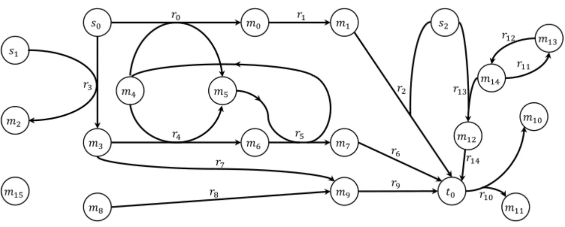
Chapter 3 Computing Synthetic Pathways 28 by σ(Z), meaning that σ is a solution structure of a synthetic problem Z. There-fore, σ is a set of reactions and Θ(σ, Z) is verifiable. Because every solution is related to a particular synthetic problem Z, for simplification in later sections, the Z is omitted. 𝑠0 𝑚4 𝑚0 𝑚5 𝑟0 𝑚6 𝑚3 𝑟4 𝑠1 𝑚2 𝑟3 𝑚7 𝑚9 𝑚1 𝑚8 𝑚15 𝑠2 𝑡0 𝑚10 𝑚11 𝑟2 𝑟1 𝑟5 𝑟6 𝑟10 𝑟8 𝑟9 𝑟7 𝑟11 𝑚14 𝑚13 𝑟12 𝑚12 𝑟13 𝑟14
Figure 3.1: Example directed hypergraph: V = {t0, s0, s1, s2, m0, m1, m2, m3,
m4, m5, m6, m7, m8, m9, m10, m11, m12, m13, m14, m15}; E = {r0, r1, r2, r3, r4, r5,
r6, r7, r8, r9, r10, r11, r12, r13, r14}
Let Zexample = hHexample, {s0, s1, s2}, {t0}i be a synthesis problem, and Hexample =
hV, Ei a directed hypergraph (Fig. 3.1). The condition 1 of Θ requires that if F
is a solution of Zexample, then T ⊆ Ψ+(F ) (Ψ+ reads as ”products of”). In this
particular example, the condition would be t0 ∈ Ψ+(F ). The second condition
requires that every metabolite, that is a reactant in F , must be satisfied except for the ones in S (there is no need to satisfy the substrates of the problem). Together, these are enough to build fully satisfied solutions. The last condition is used to eliminate meaningless solutions.
Let F0 = {r3, r4, r5, r6, r7} be a subset of π2(Hexample), then Θ(F0, Zexample) is not
a valid solution structure, although F0 is fully satisfied. Indeed, the hyperarc r7
contains no element in T and no products of r7have a consumer in F0, not obeying
the third condition. This implies that this hyperarc can be discarded, although
R0 satisfies conditions 1 and 2 of Θ.
A solution structure space S is the set of all solution structures of a synthetic problem, being defined more formally as follows.
Definition 14. (Solution Space)
Let Z = hD, S, T i be an arbitrary synthetic problem. Then, the solution space of Z, is defined by the set S, as follows:
Chapter 3 Computing Synthetic Pathways 29 S(Z) = {R : R ∈ ℘(R) | Θ(R, Z)}
The solution space is a finite set of all subsets of the universal set of reactions in the metabolic domain, such that the property of solution structure is verified in each of these sets. This set is dependent of the synthetic problem, therefore it is relative to the domain and the specific constraints of the synthesis problem.
A solution structure is normally closed under union, i.e., for given two distinct σa
and σb, then σa∪ σb is also a solution structure, since T is included in both and
every M \S metabolites in both sets are satisfied.
Theorem 1. (Solution Structure Closure under Union [23])
The union of two solution structures remains a solution structure, that is, if
σ1 ∈ S(Z) and σ2 ∈ S(Z)
then
σ1∪ σ2 ∈ S(Z)
The above theorem is not true if the reversible reactions are splitted into two
irreversible reactions (i.e., ←→r 7→ (←−r , −→r )). In these scenarios, exclusivity should
be guaranteed between the two directions, i.e., only one of the directions can be used in a solution. For the purpose of analysis of the algorithms, this property will be ignored and both of the versions are assumed as distinct.
This property allows to characterize the following types of solution structures: Definition 15. (Minimal Structure)
Let σ be a valid solution structure, then σ is minimal if and only if there is no
Chapter 3 Computing Synthetic Pathways 30 Definition 16. (Combined Structure)
Let σ be a valid solution structure, then σ is a combination of solution structures
if and only if there are two valid solution structures σx and σy, that σx∪ σy is
equal to σ and σx ( σy ∧ σy ( σx
The minimal solution structures are the most relevant, as these are able to generate other solution structures through combinations and extensions.
The next section is dedicated to the maximal structure, that is written by the symbol µ, which is also a set of reactions that is a solution structure with a special relevance for the computation of other solutions.
3.2.2
The Maximal Solution Structure
An important aspect of subgraph computation is to determine several properties of the domain. It is relevant to identify if the problem is feasible, that is, if there is at least one valid solution structure. Because the σ is closed under union, the
union of all σ ∈ SZ is a super structure that covers all valid solution structures.
This super structure is defined as the maximal structure µ.
Definition 17. (Maximal Structure [24])
Let Z = hD, S, T i be an arbitrary synthesis problem. The maximal structure of Z is defined by:
µ(Z) = S
σ∈S(Z) σ
Given an arbitrary synthesis problem Z = hD, S, T i, if a maximal structure
ex-ists, then the problem is feasible (Def. 17). The maximal structure also allows
to prune the entities of a domain. Let D = hM, Ri be an arbitrary domain, a
network mapped from this domain can have: a) unreachable metabolites (i.e.,
metabolites that are associated with no reactions); b) two or more disjoint par-titions of the network; c) reactions that are unsatisfiable. All of these elements can be discarded from the metabolic domain, as they only increase complexity for solution generating algorithms.
Chapter 3 Computing Synthetic Pathways 31 There are several algorithms to compute the maximal structure. However, the exact set is hardly achieved. The algorithms later introduced can only obtain an approximation to the maximal structure. An approximation of a set can be defined as follows:
Definition 18. (Lower approximation [49])
Let A be an exact well defined set and X be an arbitrary set.
If an element x, such that x ∈ X and x ∈ A, this is written as x ^X A (”x surely
belongs to X in A”). This is defined as a strong membership. If for every x ∈ X,
x ^X A, then X is a lower approximation of A, defined as:
Apr
X(A) = {x : x ^X A}
Definition 19. (Upper approximation [49])
Let A be an exact well defined set and Y be an arbitrary set.
If an element y, such that y ∈ Y , but is not clear whether y ∈ A or y /∈ A , this
is written as x _Y A (”y possibly belongs to Y in A”). This is defined as a weak
membership. If for every y ∈ Y , y _Y A, then Y is a lower approximation of A,
defined as:
AprY(A) = {y : y _Y A}
Let D = hM, Ri be an arbitrary metabolic domain, and Z = hD, S, T i a related synthetic problem. If, given an arbitrary set of reactions F ⊆ R, where F ⊆ µ(Z), then F is an lower approximation of the maximal structure since the elements of
R surely belongs to µ(Z). If, given an arbitrary set of reactions F0 ⊆ R, where
µ(Z) ⊆ F0, then F0 is an upper approximation of the maximal structure since
elements of R0 possibly belong to µ(Z).
For simplification, the lower approximation of the maximal structure is written as µ, such that µ = Apr