Abstract—In this article, a Disturbance Observer is utilized
to realize state feedback in the context of a rotor test rig. The rotor is actively supported by means of piezoelectric stack actuators and subject to unbalance excitation and gyroscopic effect. The presence of gyroscopic effect leads to a dependence of the system dynamics on rotary frequency of the shaft. Due to unknown disturbances in the form of unbalance excitation and system deviation due to gyroscopic effect, ordinary linear time invariant observers fail to observe the system states accurately for gyroscopic rotors, possibly leading to significant control performance reduction. To overcome this problem, a Disturbance Observer is applied to the problem. It is shown that the gyroscopic effect can be approximated accurately by an additive term in the state space equation and can thus be treated as an additional disturbance in Disturbance Observer design. Due to high steady state estimation accuracy, the presence of the Disturbance Observer does not affect steady state control performance and thus, controller and observer design are decoupled regarding control performance. Due to this fact, the controller can be designed prior to the observer despite system deviation due to gyroscopic effect and disturbances. However, since the separation principle does not hold for the system, stability proof has to be carried out by consideration of the entire closed loop system for all rotational frequencies within the operating range. A Linear Quadratic Regulator is used as a controller for the sake of simplicity. However, the proposed observer structure is applicable to arbitrary state space controllers. The resulting controller-observer combination is validated in simulation and experiment.
Index Terms—Active Vibration Control, Disturbance Observer, Gyroscopic Effect, Rotordynamics, State Space Control
I. INTRODUCTION
OTOR vibration control is an important issue in high speed rotor applications such as power plant or aircraft engine turbines. High levels of vibration reduce service life of rotating machinery and may lead to undesirable operating conditions like contact of rotating and stationary parts. It is state of the art to achieve rotor vibration attenuation by means of passive measures such as damping elements, balancing or targeted manipulation of eigenfrequencies. However, applicability of passive vibration reduction methods is limited in many practical cases and as a result, active vibration control strategies are a topic of contemporary research in the field of rotordynamics.
Manuscript received February 01, 2013. This work was supported by Deutsche Forschunsgemeinschaft within the framework of the graduate
college 1344, “Instationäre Systemmodellierung von Flugtriebwerken”.
The authors are with the Institute for Mechatronic Systems in Mechanical Engineering of the Technische Universität Darmstadt, Petersenstraße 30, 64287 Darmstadt, schittenhelm/wang/ riemann/[email protected].
Besides other active and semi-active components, electromagnetic [1], [2] and piezoelectric actuators [3], [4] have been proven to be feasible for active control of rotor vibration in the respective literature. In this article, vibration control is achieved using piezoelectric stack actuators. This actuator type provides low weight accompanied by high forces in a broad frequency range if suitable amplifiers are available. These attributes are important for active vibration control in applications that require high vibration attenuation and light-weight construction as in aircraft engines, which is the background of this study.
The heart of active vibration control systems is the controller itself. The choice of a proper control law affects the achievable control performance significantly. For vibration control of rotating shafts, feedforward as well as feedback methods are commonly applied throughout literature. Feedforward approaches are usually realized using filters, which are adapted using algorithms like the Filtered x Least Mean Square Algorithm [5] for instance. In the field of feedback control, besides simple controllers like PD or Integral Force Feedback, frequency domain approaches [1] like µ-, H∞- or H2-optimal controllers and state feedback [3], [4] are frequently utilized.
In this article, a state feedback controller, the Linear Quadratic Regulator (LQR), is applied to a rotor vibration control problem. The LQR offers relatively easy design and a comprehensible interconnection between design parameters and closed loop system dynamics. Possibly due to these reasons, the LQR is the most frequently applied state space controller in the field of rotordynamics, see e.g. [2]- [4], and also commonly utilized as a benchmark controller in other applications [6]. Moreover, stability of the LQR is robust against modeling errors in the system input matrix [6]. For these reasons and also because the focus of this paper is not controller design, but to demonstrate advantages of an observer structure, the LQR is used to achieve state feedback in this article. However, the proposed observer structure can also be utilized in the context of different state feedback controllers like controllers designed via pole placement [6] or advanced controllers that consider parametric uncertainty [7] or minimize H∞- or H2- norms of certain frequency response functions (FRFs) [8].
If state feedback is to be applied to a system and not all states are measurable using a certain sensor configuration, there is a need for an observer in order to estimate the missing states. In the context of rotors excited by unbalance and subject to gyroscopic effect, state estimation must be achieved despite the presence of unbalance excitation and system deviation due to gyroscopic effect. Ordinary linear time invariant (LTI) observers such as the commonly
State Feedback in the Context of a Gyroscopic
Rotor using a Disturbance Observer
Rudolf Sebastian Schittenhelm, Zhentao Wang, Bernd Riemann and Stephan Rinderknecht
applied (LTI) Kalman Filter fail to estimate the system states accurately as discussed in [9] and [10]. There are, just like in the case of state feedback, methods available for consideration of e.g. parametric uncertainty [7]. However, it was shown in [10] that it is admissible to treat the system deviation caused by gyroscopic effect as a harmonic disturbance. Disturbance Observers (DOs), proposed by Johnson in [11], [12] as well as Unknown Input Observers (UIOs), introduced by Wantanabe and Himmelblau in [13], account for disturbances, however, in very different ways.
UIOs, a method being commonly used in the field of fault detection and isolation [14], [15], are based on the general structure of a Luenberger Observer. Its matrices are designed in such a way that disturbances of arbitrary signal type acting on the system via a specific input matrix do not have any effect on state estimation accuracy. In the field of fault detection and isolation, this observer is commonly used to estimate system outputs and not system states as it is the case in this article. As discussed in [9], conditions for applicability of the UIO are quite restrictive and one has to deal with poorly conditioned matrices in the design procedure.
DOs rely on the assumption that the disturbance can be described by the output of a homogeneous state space model. This so-called disturbance model is included into the overall state space model in order to account for the effect of disturbances on the system. The DO is an ordinary observer, designed for this augmented system. As a result, system states as well as the disturbances are observed, leading to an estimate of the disturbances acting on the system and increased estimation accuracy regarding the system states. The DO, in contrast to the UIO, can treat disturbances which are described by the disturbance model only. Furthermore, and just like in the UIO-case, only disturbances acting on the system via a specific input matrix are accounted for.
It has been shown in [9] that conditions for applicability of DOs are less restrictive than for UIOs. Furthermore, a less accurate approximation of the disturbance input matrix and less sensors are required [9]. Due to these reasons, state observation is achieved using the DO in this article in a test rig application. It is shown that by means of state observation via a DO, control performance of an a priori designed state space controller is not affected. This article is an extension of the investigation in [3], where the coupled design of a LQR and a Kalman Filter is treated.
II. THEORY
In this section, the relevant theoretical background for the investigation in this article is given, i.e. the theory of LQRs and DOs is briefly introduced.
A. Linear Quadratic Regulator
The LQR is a state space controller, i.e. designed on the basis of a system description (1)
(1)
and minimizes the cost function [6], [16]
∫ (2)
for arbitrary initial conditions and . In (1) and (2), are the system states, the control inputs, the disturbances acting on the system, the system outputs and are system matrices with appropriate dimensions. In (1), feedthrough components are neglected for the sake of simplicity and due to the fact that no significant feedthrough components are present at the rig under consideration. Furthermore, the results in this subsection are not affected by feedthrough terms and the DO, which is treated in the next subsection, can easily be extended to systems possessing feedthrough components [17]. The control input generated by a state space controller is
(3)
with the constant controller gain . The LQR, minimizing , is given by [6], [16]
(4)
In (4), is the symmetric, positive definite solution to the Algebraic Riccati Equation [6], [16]
(5)
B. Disturbance Observer
In order to realize a state space control law (3), all system states have to be available. If not all system states are measurable, an observer is required. For an ordinary Luenberger observer,
̂ ̂ ̂ ̂ ̂,
(6)
the estimation error ̂ tends towards zero as time increases if and the matrix is stable, i.e. all its eigenvalues possess negative real parts. If there are disturbances present however, the estimation error is described by [16]
(7)
i.e. even if is stable, there will be steady state estimation error for disturbances other than e.g. impulse-like ones.
̂
(8)
In (8), ̂ is an estimate of the disturbance. This disturbance model is included in the overall system model:
[ ̂] [ ] [ ̂] [ ] ̂ [ ] [ ̂]
(9)
The design of an observer for the system (9) leads to a so-called DO. As shown by Johnson [17], the estimation error of a DO for (1) on the basis of (9) tends towards zero, provided that it is stable, can be fully described by (8) and that no model inaccuracy is present.
III. TEST RIG
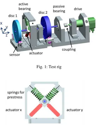
A controller-observer combination is applied to a rotor test rig in this article. There are two discs mounted on the rotor, one between the two supports and one cantilever disc, see Fig. 1.
Fig. 1: Test rig
Fig. 2: Active bearing
The rotor is supported by a passive and an active bearing, which is equipped with two piezoelectric stack actuators. Power supply is provided by means of two amplifiers, whose scaled outputs are measured by the real time system. The operating range of the actuators is 0 V – 1000 V. However, an offset voltage of 500 V is applied to the actuators during operation in order to be able apply bidirectional forces to the rotor. Thus, the maximum admissible voltage amplitude is . On the opposite sides of the piezoelectric actuators, there are springs providing pre-stress for the actuators. The active
bearing is shown in Fig. 2 in detail. The rotor is driven by means of a DC motor, installed at the passive bearing side. The displacements of the two discs into the x and y direction are measured by four eddy current sensors, see Fig. 1. The sensor signals and the amplifier output voltages are filtered by means of analogue low pass filters in order to avoid aliasing effects caused by discrete time signal analysis.
The rotor is designed to be subject to gyroscopic effect to significant extent in order to replicate a high speed rotor application. Gyroscopic effect leads to a dependence of the system dynamics on rotary frequency, i.e. time varying eigenfrequencies and eigenvectors. The rotor can be operated at up to 10.000 rpm. However, just the frequency range up to 3.300 rpm is considered in this investigation and is referred to as operating range in the following.
IV. MODELING
A model of the rotor is derived via Finite Element (FE) Analysis on the basis of Timoshenko beam theory. The bearings are modeled by means of discrete spring, mass and piezoelectric elements. In order to achieve a manageable number of degrees of freedom for controller implementation, the model is reduced to an order of 16 in state space using modal truncation technique. For the purposes in this article, it is advantageous to derive a rotor model description in the form of
( )
(10)
In (10), is the rotational frequency in rad/s,
are the rotor states, are the voltages applied to the actuators, are the disturbances, i.e. unbalance
forces, and are the displacement sensor signals. The derivation of the system matrices is discussed in the following.
Coupling of the FE model with the bearing models leads to matrices of a system of second order linear differential equations as follows:
(11)
In (11), is the vector of rotor degrees of freedom,
the vector of excitations, the symmetric, positive definite mass matrix, the symmetric, positive definite stiffness matrix and the skew-symmetric gyroscopic matrix. The proposed reduction method is based on the non-rotating system, which can be decoupled by means of real right eigenvectors, ,
, which are arranged in the modal matrix
[ ]. are the eigenfrequencies of the (undamped) non-rotating system. Introducing transformation into modal coordinates , , and left multiplication of (11) by leads to the following system of differential equations:
In (12), it is already taken advantage of that the eigenvectors are normalized in such a way that , where denotes the identity matrix. For , the differential equations in (12) are decoupled, and modal truncation to modes is applicable by simply using
[ ] instead of in (12). Damping is introduced by means of modal damping for the non-rotating system:
(13)
The damping ratios were manually tuned, together with other system parameters like the elastic properties of roller bearings and actuators, in order to replicate the transfer behavior of the system accurately. Equation (13) can be transformed into a state space description of the form
[ ] [ ] [ ]
[ ] (14)
Assuming that the gyroscopic coupling between the modes can be approximated by , the desired frequency dependent part of the system matrix in (10) is
[ ] (15)
This quasi-modal truncation is not guaranteed to lead to an accurate approximation and has to be validated. In the case of the test rig, the gyroscopic influence on the eigenfrequencies is approximated with high accuracy by the truncated model in comparison to the full model, see Fig. 3. There is literally no error introduced by the quasi-modal truncation.
Fig. 3: Eigenfrequencies vs. rotational frequency, (grey, -) full model, (black, --) quasi-modally truncated model
The inputs to the system on the right hand side of (14) can be decomposed into system excitation by unbalance forces and the actuators,
(16)
Throughout this article it is assumed that unbalances are present at the disc locations only and represents the respective unbalance forces.
Besides the rotor, there are other effects at the rig to be considered: The amplifiers possess relevant dynamics within the operating range due to limitations regarding maximum current. They are approximated by means of a second order, critically damped filter. Furthermore, the time delay caused by digital signal processing produces a phase lag, which is approximated by means of a second order padé-approximant. Both effects are described by a single model of order 8,
(17)
and coupled to the rotor model on the input side,
[ ] [
] [ ] [ ]
[ ]
̂ [ ] [ ]
(18)
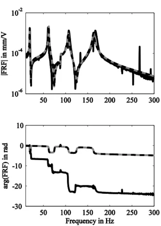
Modeled and identified FRFs from the actuator pointing into the x direction to the sensor at disc 1 pointing into the x direction at a rotational velocity of 8.000 rpm are shown in Fig. 4. The FRFs of the full model and the quasi-modally truncated model are included in order to validate the quality of the truncation once more. The models do not show relevant differences and replicate reality with high accuracy. In order to be able to predict control performance and control effort in simulations, it is advantageous to derive an approximation of the unbalances acting on the rotor. In this article, it is assumed that there are unbalances present at the disc locations only. The vector of sensor responses to these unbalances [ ] at a constant rotational frequency
is given by:
(19)
In order to be able to derive an approximation of the unbalance excitation, the complex amplitudes and
at the two unbalance induced resonances below 10.000 rpm are extracted from measurements by means of a digital implementation of the wattmeter measuring principle [18]. The desired approximation of the unbalances at the disc locations can be calculated by
[
] [
] (20)
Fig. 4: FRF from the actuator pointing into the x direction to the sensor at disc 1 pointing into the x direction at 8.000 rpm, (grey, -) full model, (black, -) identified, (black, --) quasi-modally truncated model
V. IMPLEMENTATION
In this section, the process of controller and observer design for the test rig is described. Since the DO is tuned to guarantee accurate state estimation despite the presence of gyroscopic effect and unbalance excitation, consecutive tuning of controller and observer is admissible. In the first step, a state space controller is found which leads to the desired control performance. Subsequently, one has to find a DO, which leads to closed loop stability for the whole operating range. In both steps, i.e. controller and observer design, noise amplification is considered. Since manual parameter tuning for controllers and observers is time-consuming in the case of the rig and presumably all rotors being subject to gyroscopic effect, a genetic optimization algorithm [19] is applied to the problem, which is available in MATLAB [20]. Discussion of the algorithm would be beyond the scope of this article, for more information about genetic optimization algorithms see [19].
A. Controller Design
A LQR is applied to the problem of the unbalance excited rotor in this article, due to the fact that the LQR is relatively simple to design. The focus of this paper is not the controller design, but to show an option for observer design for gyroscopic rotors excited by unbalance which preserves the desired control performance.
Obviously, the cost function (2) is not a representative measure of unbalance induced vibration and thus one may raise the question, how the LQR fits to the problem treated in this investigation. (2) can rather be considered to be a
measure of settling time of the system. However, one can influence the damping rations of certain modes by appropriate weighting and thus affect the unbalance induced resonance amplitudes, which are inversely proportional to the respective damping ratios.
In the controller design process, the following cost function is minimized by means of a genetic optimization algorithm:
{
[ ]
| | [ ]
‖ ‖ [ ]
∫ ∑ | |
(21)
In (21), is the FRF matrix from an assumed noise in the system states, to the actuator voltages with its feedthrough component eliminated:
(22)
The H2-norm of this FRF matrix gives just a rough idea of the closed loop noise amplification level to be expected. The actual noise amplification behavior from sensor noise to actuator voltages can only be analyzed for the combination of controller and observer. However, (22) is, from the authors’ point of view, the best possibility to assess noise amplification prior to observer design.
In (21), the undesirable cases of instability, actuator overload and high noise amplification are considered by means of assigning infinite cost to the respective controllers. This option for handling these cases is chosen instead of treatment by means of constraints in the optimization because of the computationally involved treatment of nonlinear constraints. The conditions are to be checked for all [ ], i.e. for the whole operating range due to the dependence of on rotational frequency. This is realized by means of checking for a number of discrete
[ ]. For the reasons discussed in [3], the linear time variant (LTV) stability proof is skipped under the assumption of a slowly varying system [21] and LTI stability is checked at the discrete .
The value as well as bounds for the controller design parameters are determined on the basis of the controller presented in [3]. The authors recommend to implement a controller by manual tuning of the controller parameters proposed in [3] in order to get an idea of these values, when following the controller design procedure in this article.
In the optimization routine, not only the controller parameters but also the design point frequency is varied, i.e. the LQR is calculated on the basis of the system
(23)
B. Observer Design
For observer design, it is once again assumed that unbalances act on the system at the disc locations only, i.e. the matrix of the corresponding model possesses four rows corresponding to force inputs at the discs into the x and y direction respectively. The observer is designed for a system of the form:
[ ̂] [ ̃ ] [ ̂] [ ] ̂ [ ] [ ̂]
(24)
An obvious choice of system matrices would be to use
and ̃ for observer
implementation and, like in (23), a specific design point system for calculation of the observer feedback matrix . However, this would imply that a LTV system of order 32 has to be implemented in real time. An interesting approach to overcome this problem is to use a constant observer matrix at some specific design point frequency
(25)
and to consider the term caused by gyroscopic effect in (18) as additional sinusoidal disturbances [10],
̃̃ ̃ [ ] [ ] (26)
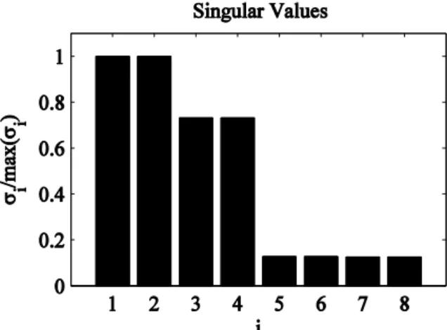
In this way, however, the order of the observer is even higher than for the case and ̃ . To overcome this problem an approximation ̃ is utilized, i.e. ̃ ̃, which possesses just columns and full column rank. It is obtained on the basis of a singular value decomposition of ̃̃ [15]:
̃ [ ]
̃̃ [ ( ) ]
(27)
The more singular values one considers, the more accurately the resulting matrix ̃ represents ̃̃. The 8 largest magnitude singular values of ̃̃, normalized to the largest one, are shown in Fig. 5. In this investigation, approximations ̃ and ̃ , possessing two and four columns respectively, are utilized for observer implementation. The proposed observer structure is implemented in real time by means of a LTI system of order 24, corresponding to the system model at the design point frequency, and a LTV system corresponding to the disturbance model, which possesses an order of twice the number of rows of ̃. Discretization of this LTI model is achieved using bilinear approximation [22] and calculation of the respective rotary frequency dependent system matrices by hand in order to achieve a computationally efficient real time program.
Fig. 5: Singular values of the disturbance input matrix, normalized to the largest magnitude singular value
For sinusoidal excitation, a disturbance model is given by [23]
[ ]
[ ] (28)
Due to the inclusion of the disturbance model into the observer matrices, conditions for observability depend on the disturbance model as well as the disturbance input matrix. In [23], a necessary observability condition for the system (9) with a disturbance model (28) is given and proven:
If (A,C) is an observable pair and E is of full column rank, then the system
([
] [ ])
is observable only if
i.e. the number of independent disturbances considered must be smaller or equal to the number of independent measurements.
(29)
In the investigation in this article, no observer can be found using just the displacement sensors despite the rank condition being satisfied. To overcome this problem, the measured amplifier output voltages are used as additional sensor signals, i.e. the output matrix
̃ [ ] (30)
is utilized for observer design and implementation.
The observer matrix is generated by applying the LQR to the dual system, i.e. calculation of a LQR for
and transposing the result. Like in the controller design procedure, the observer feedback matrix is generated utilizing a genetic optimization algorithm. However, finding a stabilizing solution is more difficult in the case of the observer. Thus, the parameter tuning is achieved in two steps. In the first one, the optimization algorithm is utilized to maximize the region of robust stability without consideration of noise amplification. In the second step,
{ ‖ [ ]
‖ (32)
is minimized while using the optimal solution of step one in order to generate a promising initial population [19] of the genetic algorithm. In (32), is the FRF matrix from sensor noise inputs to actuator voltages.
There is no need to include other performance measures like in (21) in the optimization, because the DO does not affect them if it leads to a stable closed loop and the approximation
̃ is sufficiently accurate. Like in the case of the controller, the design point frequency is used besides the controller design parameters as free parameter in the optimization process.
VI. RESULTS
Results achieved with the controller-observer combination in simulation and experiment are presented and discussed in this section. All simulation results are achieved using steady state frequency domain analysis, whereas the experimental data is processed by means of a digital implementation of the wattmeter measuring principle [18] in order to focus on the synchronous vibration of the rotor.
The results achieved with two different DOs, calculated using ̃ and ̃ respectively, are presented in order to show the effect of accuracy of the approximation of ̃̃ on control performance.
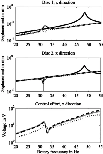
Simulation results for 3 different configurations are shown in Fig. 6. Vibration amplitudes as well as control
inputs are derived by means of “perfect observation”, i.e.
feeding back the system states without an observer, and by utilizing observers generated by using ̃ and ̃ . It is observed that the accuracy of ̃ affects the resulting control performance and the control effort. The effect is more severe for the control effort than for control performance. However, results show that good vibration attenuation can still be achieved, such that the overall system can still be considered feasible, even by means of a rather inaccurate approximation ̃ . This statement is in agreement with [9], where a rotor without gyroscopic effect is treated.
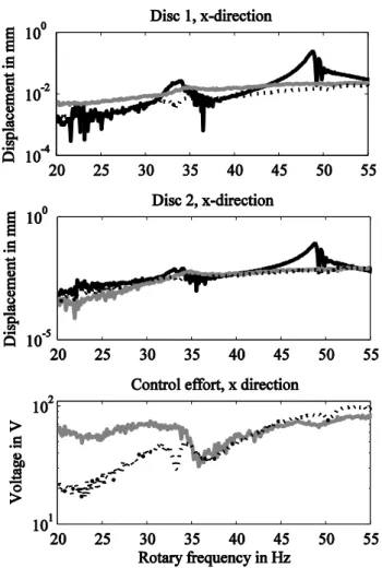
Fig. 7 shows the experimental results achieved with the two observers. As in the simulation results, control performance of the closed loop systems involving the two observers is very similar, whereas there is some difference in control effort as is the case in the simulation results.
Also, control performance is predicted accurately by the model. The control effort shows some deviation from the simulation results, particularly in the lower rotary frequency range. Since the simulation results indicate that errors in ̃ lead to estimation errors, especially in the control effort, it is
assumed that this is partially because the matrix ̃̃ [ ] is subject to modeling errors. Recall that , which was used for observer design as well as to obtain the simulation results shown in Fig. 6, was derived under the assumption that unbalances act on the shaft at the disc locations only, whereas at the test rig it is an unbalance distribution that excites the rotor. Another source of uncertainty is actuator nonlinearity, which is not considered in the simulation.
Fig. 6: Simulation results, displacement amplitudes at discs 1 and 2 into the x direction: (black, -) no control, (black, --) perfect observation, (grey, -) observer ̃ , (black, :) observer ̃ . Control effort: (black, --) perfect observation, (grey, -) observer ̃ , (black, :) observer ̃ .
VII. CONCLUSION
Design and implementation of Disturbance Observers for realization of state feedback in the context of a rotor being subject to unbalance excitation and gyroscopic effect was discussed and feasibility was validated in simulation and experiment. It was shown that gyroscopic effect can be accurately approximated by an additive term in the state space equation of the rotor system and can be treated as an additional disturbance. It was demonstrated how an approximate disturbance input matrix can be derived and the influence of the accuracy of this approximation on control performance and control effort was investigated.
controller designed prior to observer design is preserved despite the presence of unbalance excitation and gyroscopic effect and thus, consecutive tuning of controller and observer is admissible.
Fig. 7: Experimental results, displacement amplitudes at discs 1 and 2 into the x direction: (black, -) no control, (grey, -) observer ̃ , (black, :) observer ̃ . Control effort: (grey, -) observer ̃, (black, :) observer ̃ .
ACKNOWLEDGMENT
This work is based on a research project in cooperation with Rolls Royce Deutschland Ltd & Co KG. The authors thank Ms. Sina Koch and Mr. Shengjun Lu for their contribution to the project during preparation of their master theses.
REFERENCES
[1] B. Riemann, A. E. Perini, K. Lucchesi Cavalca, H. Fiori de Castro, and S. Rinderknecht, "Oil Whip Instability Control Using μ-Synthesis Technique on a Magnetic Actuator," Journal of Sound and Vibration, vol. 332, no. 4, pp. 654-673, 2013.
[2] N. Tanaka, N. Uchiyama, T. Watanabe, and K. Seto, "Levitation and Vibration Control of a Flexible Rotor by Using Active Magnetic Bearings," Journal of System Design and Dynamics, vol. 3, no. 4, pp. 551-562, 2009.
[3] R. S. Schittenhelm, M. Borsdorf, B. Riemann, and S. Rinderknecht, "Linear Quadratic Regulation of a Rotating Shaft being Subject to Gyroscopic Effect," in Lecture Notes in Engineering and Computer Science: Proceedings of The World Congress on Engineering and Computer Science 2012, San Francisco, USA, 24-26 October, 2012, pp. 1292-1297.
[4] F. Lebo, S. Rinderknecht, and M. Özel, "Model-Based Control of an Elastic Aircraft Engine Rotor with Piezo Stack Actuators," in IEEE 17th International Conference on IE&EM, Xiamen, 2012.
[5] O. Lindenborn, B. Hasch, and R. Nordmann, "Vibration Reduction and Isolation of a Rotor in an Actively Supported Bearing Using Piezoelectric Actuators and the FXLMS Algorithm," in 9th International Conference on Vibrations in Rotating Machinery, Exeter, 2008.
[6] E. Hendricks, O. Jannerup, and P. H. Sorensen, Linear Systems Control. Berlin, Heidelberg, Germany: Springer, 2008.
[7] W. Breinl and G. Leitmann, "Zustandsrückführung für dynamische Systeme mit Parameterunsucherheiten (State Feedback for Uncertain Dynamical Systems)," Regleungstechnik, vol. 31, no. 3, pp. 95-103, 1983.
[8] C. Yongjun and Z. Changsheng, "Active Vibration Control based on Linear Matrix Inequality for Rotor System under Seismic Excitation,"
Journal of Sound and Vibration, vol. 314, pp. 53-69, 2007.
[9] R. S. Schittenhelm, Z. T. Wang, and S. Rinderknecht, "Observer Design for Rotating Shafts Excited by Unbalance," in Proceedings of the Tenth International Conference on Vibrations in Rotating Machinery, London, UK, 2012, pp. 357-366.
[10] Z. Wang, R. S. Schittenhelm, and S. Rinderknecht, "Observer Design for Unbalance Excited Rotor Systems with Gyroscopic Effect," in
Proceedings of the IEEE International Conference on Mechatronics and Automation, 2012.
[11] C. D. Johnson, "Optimal control of the linear regulator with constant disturbances," IEEE Transactions on Automatic Control, vol. 13, no. 4, pp. 416 - 421 , 1968.
[12] C. D. Johnson, "Further study of the linear regulator with disturbances -The case of vector disturbances satisfying a linear differential equation ," IEEE Transactions on Automatic Control, vol. 15, no. 2, pp. 222 - 228 , 1970.
[13] K. Watanabe and D. M. Himmelblau, "Instrument fault detection in systems with uncertainties," International Journal of Systems Science, vol. 13, no. 2, pp. 137-158, 1982.
[14] P.M. Frank and J. Wünnenberg, "Robust fault diagnosis using unknown input schemes," in Fault Diagnosis in Dynamic Systems: Theory and Application, P. M. Frank, R. N. Clark In R. J. Patton, Ed. Upper Saddle River, New Jersey: Prentice Hall, 1989, pp. 47-98. [15] J. Chen and R. J. Patton, Robust Model-Based Fault Diagnosis for
Dynamic Systems. Boston, Dodrecht, London: Kluwer Academic Publishers, 1999.
[16] J. Lunze, Regelungstechnik 2, 3rd ed. Berlin, Heidelberg: Springer, 2005.
[17] C. D. Johnson, "On observers for systems with unknown and inaccessible inputs," International Journal of Control, vol. 21, no. 5, pp. 825-831, 1975.
[18] A. Argeseanu, E. Ritchie, and K. Leban, "New Balancing Equipment for Mass Production of Small and Medium-Sized Electrical Machines," in 12th International Conference on Optimization of Electrical and Electronic Equipment, Brasov, 2010, pp. 506 - 511. [19] X., Gen Mitsuo Yu, Introduction to Evolutionary Algorithms. London:
Springer, 2010.
[20] A. Chipperfield, P. Fleming, H. Pohlheim, and C. Fonseca, "Genetic Algorithm Toolbox for use with MATLAB," Department of Automatic Control and Systems Engineering, University of Sheffield, Sheffield, 1994.
[21] H. H. Rosenbrock, "The stability of linear time-dependent control systems," International Journal of Electronics and Control, vol. 15, pp. 73–80, 1963.
[22] P. Apkarian, "On the Discretization of LMI-Synthesized Linear Parameter-Varying Controllers," Automatica, vol. 33 , no. 4, pp. 655 - 661 , 1997.
[23] Z. Wang, R. S. Schittenhelm, and S. Rinderknecht, "Augmented Observer for Fault Detection and Isolation (FDI) in Rotor Systems," in