Design and Performance Analysis of FFT in
OFDM applications using VHDL
1
Renu yadav
M.Tech Scholar
Dehradun Institute of Technology, Uttrakhand Technical University, Dehradun India E-mail: renuyadavdbit@yahoo.com
2Mukesh Pathela Head of department,
Department of Electronics & Communication Engineering, Shivalik College of Engineering, Dehradun India E-mail: mukeshpathela@gmail.com
Abstract
For Orthogonal Frequency Division Multiple Access (OFDMA) system module, there is a need for an efficient alterable point FFT block. The research work focuses the design and synthesis of FFT module which is designed to meet the requirements of OFDM & OFDMA system. In the widely used OFDMA systems, the FFT and IFFT pairs are used to modulate and demodulate the data constellation on the subcarriers. The research paper presents a high level implementation of a high performance FFT for OFDM Modulator and Demodulator. Field programmable gate arrays (FPGAs) are extensively used in rapid prototyping and verification of a conceptual design and also used in electronic systems when the mask-production of a custom IC becomes prohibitively expensive due to the small quantity. HDL based VLSI design requires a careful forethought about the entire design process with special attention to transistor sizing, floor planning, layout routing, clock and power distribution with timing analysis. VHDL language is used to present a detail design of FFT block using Xilinx 14.1 software, ModelSim (SE) 10.1b software for the simulation, and verify on the Spartan3E FPGA. Keywords
Fast Fourier Transform (FFT), Inverse Fast Fourier Transform (IFFT), Very Large Scale of Integration (VLSI) 1. Introduction
In modem communication systems Orthogonal Frequency Division Multiple (OFDM) [1] [2] plays an important part, and it will be replaced by Orthogonal Frequency Division Multiple Access (OFDMA) [5] [9] in the next generation wireless communication systems such as WiMAX [1] [2] and 3G-LTE standard. The OFDMA PR [5] is based on OFDMA modulation, which comprises of OFDM modulation as well as subcarrier allocation. Therefore, it is significant to focus more attention on wireless communication technology. IEEE Std 802.16 family [1] is a wireless metropolitan area network standard which is detailed in fixed service in 2004 edition and the 2005 edition for mobile access technology.
Orthogonal Frequency Division Multiplexing (OFDM) is a multicarrier transmission technique that divides the available spectrum into multiple carriers in which each one is being modulated by a low rate data stream. OFDM is similar to FDMA [10] in that the multiple user access is achieved by subdividing the available bandwidth into multiple channels band, which is then allocated to users. So, OFDM uses the spectrum much more efficiently by spacing the channels much closer together. It is possible by making all the carriers orthogonal to each another, preventing interference between the closely spaced carriers.
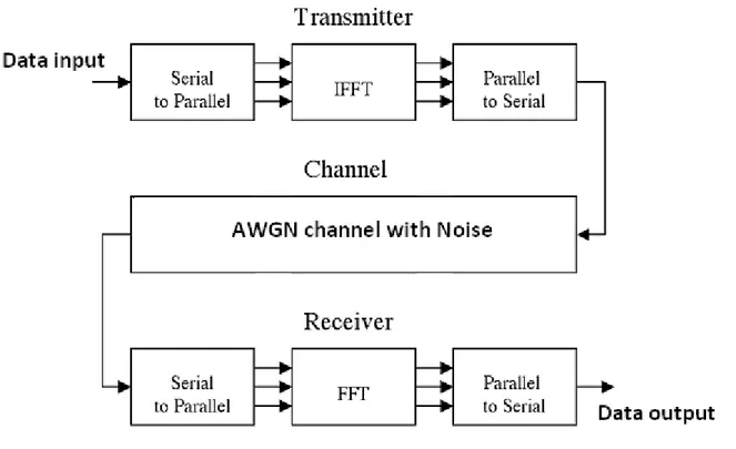
2. OFDM block diagram
The block diagram of OFDM is shown in figure 1.The symmetrical arrangement about the vertical axis is necessary for using the IFFT to manipulate input data. An inverse Fast Fourier transform (IFFT) converts the frequency domain data set into samples of the corresponding time domain representation of this data. Specifically, IFFT is very much useful for OFDM because it generates samples of a waveform with frequency components satisfying orthogonality conditions among its carriers. Then, there is the need of parallel to serial block that creates the OFDM signal by sequentially outputting the time domain samples.
Figure 1 OFDM block diagram
The time domain samples are passed to the channel simulation allows examination of common wireless channel characteristics such as noise, multipath, and clipping. By adding random data to the transmitted signal, simple noise can be simulated for performance analysis. Multipath simulation involves adding attenuated and delayed copies of the transmitted signal to the original signal. This simulates the problem in wireless communication when the signal propagates on multiple paths. For an example, a receiver may observe a signal via a direct path as well as a path that bounces off a building or mountain. Finally, clipping action is taken to simulate the problem of amplifier saturation. This scheme addresses a practical implementation problem in OFDM where the peak to average power ratio is high. In demodulation section, the receiver performs the inverse of the transmitter. At channeling end first, the OFDM data are split from a serial stream into parallel sets. The Fast Fourier Transform (FFT) converts the time domain samples back into a frequency domain representation. The magnitudes of each frequency components are correspond to the original data. Finally, at receiving end, the parallel to serial block converts this parallel data into a serial stream to recover the original input data.
3. Fast Fourier Transform (FFT)
The fast Fourier Transform (FFT) is an algorithm that efficiently computes the discrete Fourier Transform (DFT). The DFT of sequence x(n) over length N is given by the relation which is a complex valued sequence X(k).
/ ,
The equation can be represented by the relation
/ ,
Here WN represents the complex valued phase factor, which is the Nth root of unity and expressed as
/
Similarly the equation of IDFT is given as
Figure 2 Flow graph of DIT FFT (N=8) as butterfly structure [15] The value of weight coefficients are
cos sin .7 7 .7 7
cos sin
cos sin .7 7 .7 7
4. Modelsim and Xilinx outputs of 8-point FFT
The Modelsim output of 8 point FFT is shown in figure 3 and 4. In the diagrams X(0)…… X(7) presents the input to FFT module and Y(0)….Y(7) resents the output of FFT module. Similarly Figure 4 shows the discrete data transfer by FFT with complex numbers also. Y(0)……Y(7) presents the output of FFT and output of IFFT. Functional simulation on Modelsim depends on the following step inputs.
Step input1: Force the value of data_in and X(0) to X(7) and run
Step input 2: The output of FFT and input of FFT Y(0)…. Y(7) are in separated in real and imaginary parts because the output of FFT may be a complex number real_Y(0)….. real_Y(7) are the real parts and im_Y(0)…….im_Y(7) are imaginary parts of output.
Figure 3 Modelsim output of 8-point FFT
Figure 4 Modelsim output of 8-point FFT with complex numbers 5. Device utilization and timing summary
Device utilization report is the report of used device hardware in the implementation of the chip and timing report is the minimum and maximum time to reach the output. Timing parameters are synchronized with the clock signal. Timing details provides the information of net delay, minimum period, minimum input arrival time before clock and maximum output required time after clock
Optimization Goal : Speed
Optimization Effort : 1
Slice Utilization Ratio : 100
BRAM Utilization Ratio : 100
DSP48 Utilization Ratio : 100
Slice Utilization Ratio Delta : 5
Macro Statistics # No of Multipliers : 12
33x33-bit multiplier : 12
# No of Adders/Subtractors : 25
No of 32-bit adder : 16
No of 32-bit subtractor : 9
Macro Statistics # Multipliers : 12
33x33-bit multiplier : 12
# Adders/Subtractors : 25
32-bit adder : 16
32-bit subtractor : 9
# GND : 1
# INV : 64
# LUT1 : 2
# LUT2 : 1802
# LUT3 : 58
# LUT5 : 1
# LUT6 : 59
# MUXCY : 1821
# VCC : 1
# XORCY : 1929
# IBUF : 256
# OBUF : 515
# DSPs : 18
# DSP48E : 18
Device utilization summary: Device EP2S90F1020I4 Slice Logic Utilization: Number of Slices : 1986 out of 72768 15%
Number used as Logic : 1986 out of 72768 15%
Slice Logic Distribution: Number of LUT Flip Flop pairs used : 1986
Number with an unused Flip Flop : 1986 out of 1986 100% Number with an unused LUT utilizatio : 0 out of 1986 0%
Number of LUT-FF pairs used : 0 out of 1986 0%
IO Utilization: Number of Ios : 71
Number of bonded IOBs sources : 71 out of 172 41% Specific Feature Utilization: Number of DSP48Es elements : 18 out of 24 75%
Speed Grade : 2
Maximum combinational path delay : 17.988 ns Total memory usage is : 201920 kilobytes
A flow chart to compare the results in VHDL and MATLAB is shown in the figure 5. The results are corresponding to Minimum time, Maximum time and path delay values obtained from the synthesis summary of Xilinx software. In the MATLAB the delay estimations are in milliseconds and in VHDL nanoseconds. So, VHDL implementation can be a best solution in comparison to MATLAB.
Fig. 5 Comparison of delay (Minimum, Maximum and path delay) in VHDL and MATLAB 6. Conclusion and future work
The hardware chip design and synthesis done for FFT module in VHDL is done on Xilinx 14.2 software. The simulation results are tested on Modelsim 10.1 b student edition successfully. The FFT modules are tested for the different test cases. FFT is used in demodulation schemes and data transfer is checked out with FFT/IFFT transreceiver used in OFDM and ODDMA applications.
The existing work can be used for Wimax and wireless technology in which fast computations are required. FFT implementation can be a good solution for multiple input multiple output (MIMO) system. So, it is possible to implement for MIMO OFDM and MIMO OFDMA systems. The value of time delay is very less in nanoseconds in VHDL realization and in MATLAB it is in milliseconds. The design is applicable to develop ‘N’ point FFT. The feature of pipeline and parallel processing supports to execute the design upto ‘N’ points which are applicable to OFDMA applications.
REFERENCES
[1] Chandrakanth.V, Wasim Nasir, Paramananda Jena and Ramachandra Kuloor “Novel Architecture for Hardware Efficient FPGA Implementation of Real Time Configurable “Variable Point FFT” Using NIOS II ” 978-1-4244-2871-7/09/$25.00 ©2009 IEEE. [2] Pawan Verma, Harpreet Kaur, mandeep Singh, Balwinder Singh“VHDL implementation of FFT/IFFT Blocks for OFDM”
978-0-7695-3845-7/09 $25.00 © 2009 IEEE2009 International Conference on Advances in Recent Technologies in Communication and Computing page (1116-118)
[3] Proakis, J.G,“Digital Communications” McGraw-Hill Series in Electrical and Computer Engineering, 2001 4th edn. [4] Loo Kah Cheng, “Design of an OFDM Transmitter and Receiver using FPGA”, UTM,thesis 004.
[5] M.Merlyn, ECE,Jayaram College of Engg & Tech,,Trichy, India “FPGA Implementation Of FFT Processor With OFDM Transceiver, 2010 International Conference on Signal and Image Processing page (485-489) @ 2010 IEEE
[6] Keller, T., and Hanzo, L.: ‘Adaptive multicarrier modulation: A convenient framework for time-frequency processing in wireless communications’, Proc. IEEE, 2000 , vol 88, pp. 611–642
[7] K.Harikrishna, T. Rama Rao, Vladimir A. Labay, “FPGA Implementation of FFT Algorithm for IEEE 802.16e (Mobile WiMAX)” International Journal of Computer Theory and Engineering, Vol. 3, No. 2, April 2011 pp (197-202
[8] Lokesh C, Dr. Nataraj K. R “Implementation of an OFDM FFT Kernel for WiMAX” International Journal Of Computational Engineering Research (ijceronline.com) Vol. 2 Issue. 8pp (74-80)
[9] IEEE TRANSACTIONS ON COMMUNICWIONS, Va. NO. OCTOBER 2004: A Technique for Orthogonal Frequency Division Multiplexing Frequency Offset Correcti*on Paul H. MQose, Member, IEEE.
[10] Implementation of Fast Fourier Transform (FFT) on FPGA using Verilog HDL An Advanced-VLSI Design-Lab (AVDL) Term-Project, VLSI Engineering Course, Autumn 2004-05, Deptt. Of Electronic & Electrical Communication, Indian Institute of Technology Kharagpur. 0 1 2 3 4 5 6 7 8 9 10
Min Time Max Tme Path delay
VHDL result
[11] S Sukhsawas, K Benkrid. A High-level Implementation of a High Performance Pipeline FFT on Virtex-E FPGAs. Proceedings of the IEEE Comp. Society Annual Symp. on VLSI Emerging Trends in Systems Design (ISVLSI’04). 0-7695-2097-9/2004.
[12] K. Harikrishna, T. Rama Rao and Vladimir A. Labay, “A RADIX-22 Pipeline FFT for Ultra Wide Band Technology”, International Conference on Computer & Network Technology (ICCNT), conference proceedings published by World Scientific Press, Singapore. Chennai, India, Jul 24-28, 2009.
[13] S. He and M. Torkelson. A new approach to pipeline FFT processor, 10th Int. Parallel Processing Symp. (IPPS’96), p. 766–770, 1996. [14] Digital Signal Processing: Principles, Algorithms and Applications (3rd Edition) by John G. Proakis and Dimitris K Manolakis -
Prentice-Hall, Inc., - Oct 5, 1995.
[15] Alan V. Oppenheim, Ronald W. Schafer, John R. Buck, Discrete-Time Signal Processing.Prentice Hall, Second edition, pp. 646-652,1999.
[16] S Salivahanan, A Vallavaraj,C Gnanapriya Digital Signal Processing Tata Mcgraw Hill .
![Figure 2 Flow graph of DIT FFT (N=8) as butterfly structure [15]](https://thumb-eu.123doks.com/thumbv2/123dok_br/18242835.341385/3.892.122.800.108.527/figure-flow-graph-dit-fft-n-butterfly-structure.webp)


