Repositório ISCTE-IUL
Deposited in Repositório ISCTE-IUL:
2019-01-08Deposited version:
Publisher VersionPeer-review status of attached file:
Peer-reviewedCitation for published item:
Barka, A., Dehan G., Matos, S., Costa, J. R. & Fernandes, C. A. (2018). FETI DDM methodologies for the simulation of high gain Ka-band Transmit arrays (single and dual band). In 39th ESA Antenna Workshop on Innovative Antenna Systems and Technologies for Future Space Mission. Noordwijk
Further information on publisher's website:
https://atpi.eventsair.com/QuickEventWebsitePortal/39th-esa-antenna-workshop/antenna
Publisher's copyright statement:
This is the peer reviewed version of the following article: Barka, A., Dehan G., Matos, S., Costa, J. R. & Fernandes, C. A. (2018). FETI DDM methodologies for the simulation of high gain Ka-band
Transmit arrays (single and dual band). In 39th ESA Antenna Workshop on Innovative Antenna Systems and Technologies for Future Space Mission. Noordwijk. This article may be used for non-commercial purposes in accordance with the Publisher's Terms and Conditions for self-archiving.
Use policy
Creative Commons CC BY 4.0
The full-text may be used and/or reproduced, and given to third parties in any format or medium, without prior permission or charge, for personal research or study, educational, or not-for-profit purposes provided that:
• a full bibliographic reference is made to the original source • a link is made to the metadata record in the Repository
FETI DDM methodologies for the simulation of
High Gain Ka-Band Transmit arrays(single and
dual band)
André Barka, Guillaume Dehan
Département Electromagnétisme et Radar, Université Fédérale de Toulouse, ONERA Toulouse, France
Andre.barka@onera.fr
Sergio Matos, Jorge R. Costa, Carlos A. Fernandes
Instituto de Telecomunicacoes, Instituto Superior Tecnico, (IT/IST) Instituto Universitario de Lisboa, (ISCTE-IUL)
Lisbon, Portugal
Abstract—This paper is presenting Finite Element Tearing
and Interconnecting (FETI) simulation results of large scale single and dual Ka-band lens transmit-arrays obtained on massively parallel clusters. The computation times observed with the FETI method allow us to consider using it in the optimization phase of such transmit-arrays. (Abstract)
Keywords—Ka-band transmit-array, lens, FETI domain decomposition
I. INTRODUCTION
Ka-band high gain satellite antennas providing broadband access services are required for installation on High Throughput Satellites (HTS) and high altitude platforms (HAPs). Recent works show the interests of a transmit-array (Fig. 1,Fig. 2) used for ground terminal to conciliate high gain (30 dBi) with wide beam scanning (0 to 50°) and antenna height (F/D≤1) for single band (30 GHz) [1] and dual band (20 and 30 GHz)[2].
The full wave simulation of these Fresnel lenses requires considerable computation effort. Indeed, the dimensions of the lens of 30 dBi gain are approximately 20 λ x 15 λ at 30 GHz and the electromagnetic problem to be solved is non-periodic.
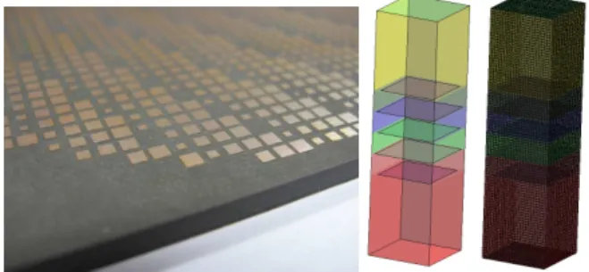
The single band lens is composed of 4524 phase-shifting cells chosen from 63 different constitutive unit cells. These unit cells are composed by five metallized layers of concentric squared patches on four substrate layers of Rogers Duroid 5880 (εr=2.2 and tan δ = 0.0009).The in-plane width of the unit cell
is P= 2.5 mm. The periodic simulation methods are therefore unusable here, whereas conventional full wave simulators require very important computing times as well as RAM memory.
Fig. 1. Single band 30 dBi lens antenna (DOI: 10.1109/TAP.2015.2484419)
The dual band lens operating at 20 GHz and 30 GHz (Fig. 3) is composed of 2352 cells. The 31 dual band unit cells designed in [2] (Fig. 4) are properly arranged to provide beam collimation. These unit cells are composed by seven metallized layers of concentric squared patches and strip loops printed on six substrate layers of Rogers Duroid 5880 (εr=2.2 and tan δ =
0.0009). The metallization can be modelled by a perfect electromagnetic conductor (PEC) with zero thickness. The thickness of each dielectric layer is s = 1.617 mm. The in-plane width of the unit cell is P= 3.5 mm.
The objective of this presentation is to evaluate the potentialities of the domain decomposition method FETI-2LM implemented in the FACTOPO tool for the simulation of large transmit arrays on massively parallel clusters using MPI programming. For this purpose, recent results obtained in the context of RCS reduction, using the FETI-2LM technique ([3],[4]) have been completed for antenna gain simulations. They rely on finite element resolutions of the local problems of each of the phase-shifting cells and an iterative connection of the subdomains with the implementation of Robin type transmission conditions on the interfaces ([4]).
Fig. 3. Dual band transmit array
Fig. 4. Dual band unit cell ( [2])
II. FETI SIMULATIONS
A. HPC cluster used for benchmarking
The simulations are implemented on the Bull high-performance parallel machine “Occigen” of the “Centre Informatique National de l’Enseignement Superieur” (CINES). This machine has a total of 2,106 computing nodes with two Intel Xeon processors Haswell E5-2690v3 clocked at 2.6 GHz
and each equipped with 12 cores. Each computing node has 24 cores with 5 GB memory each.
B. Mesh and FETI strategy
The single band lens operating at 30 GHz [1] is constituted by 4524 phase shifting cells belonging to a set of 63 elementary cells and the dual band lens is composed of 2352 cells. The problem is then definitively non periodic as illustrated by Fig. 2. In our domain decomposition strategy, only the meshes of the elementary cells are sent to a core processor and the total mesh of the lens is not generated for the simulation.
C. Single band lens: simulation and measurements results
We illuminate the lens with a standard 14.5 dBi horn antenna oriented such that the E-field is parallel to the shortest dimension of the horn. The horn is positioned at the focal distance F=100 mm below the lens and the analysis is done at 30 GHz (Fig. 1).
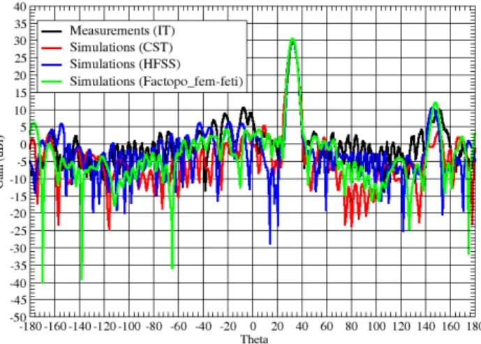
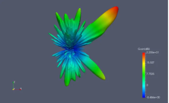
The 30 dBi full lens problem including the horn source is requiring 3.12 billion volume unknowns, 631 million interface unknowns and is solved on 15,688 Intel E5-2690v3 cores in less than 10 minutes per beam. The memory per core processor consumed is 2.5 GB. The FETI gain diagrams are considered acceptable compared to measurements, CST TD time domain and HFSS FE-BI ([5]) frequency domain simulations results obtained on 28 Intel E5-2670v2 cores (Fig. 5,Fig. 6,TABLE I. ). The computation times observed with the FETI method allow us to consider using it in the optimization phase of such transmit-arrays.
Fig. 5. Measured and simulated gain radiation patterns with a centered horn source
Fig. 6. Single band lens: measured and simulated Gain radiation patterns for different beam tilt angles (30 GHz)
Cores Ellapse Time Memory
CST 12 E5-2620 6 hours 64 Gb
HFSS 20 E5-2670v2 25 hours 100 Gb
FETI 15,688 E5-2690v3 588 secondes 2.5 Gb / core
TABLE I. SINGLE BAND COMPUTATION CHARACTERISTICS (TRANSMITT
-ARRAY FED BY HORN)
D. Dual band lens: simulation and measurements results
Two 15-dBi standard-gain rectangular horn antennas are used to illuminate the transmit array at each band (Fig. 7), with their phase centers positioned at 100 mm distance from the bottom face of the transmit array. For each lens position, one horn orientation should be simulated (y-pol) as shown in Fig. 7. 30 GHz horn Gain: 14.47 dBi Phase centre: (0,0,-2.1) (mm) 20 GHz horn z=0 Gain: 14.56 dBi Phase centre: (0,0,-1.1) (mm) z=0
Fig. 7. Models of the horns antennas used as feed for the dual band lens: Flann Microwave Nº 20240-15 for 20 GHz and Flann Microwave Nº 22240-15 used
The results presented hereafter concern the simulations at 20 GHz. The simulations obtained at 30 GHz will be presented during the conference. The full lens problem including the horn source is requiring 2.26 billion volume unknowns, 478 million interface unknowns and is solved on 9,601 Intel E5-2690v3 cores in 35 minutes per beam. The memory per core processor consumed is 1.7 GB. The FETI gain diagrams are considered
acceptable compared to measurements (TABLE II. , Fig. 8,Fig. 9,Fig. 10,Fig. 11).
Cores Ellapse Time Memory
FETI 9,601 E5-2690v3 35 minutes 1.7 Gb / core
TABLE II. DUAL BAND COMPUTATION CHARACTERISTICS (TRANSMITT
-ARRAY FED BY HORN)
Fig. 8. Dual band lens: measured and simulated Gain radiation patterns for different beam tilt angles at (20 GHz)
Fig. 9. Dual band lens: simulated gain radiation patterns for a=0 mm (20 GHz)
Fig. 10.Dual band lens: simulated gain radiation patterns for a= -15 mm (20 GHz)
Fig. 11.Dual band lens: simulated gain radiation patterns for a=+44 mm (20 GHz)
ACKNOWLEDGMENT
The research hosted by the Instituto de Telecomunicacoes in Lisbon and leading to part of these simulation results has received funding by French Ministry of Defense (DGA) through a 2016 ERE convention DGA/ONERA (Grant 2016.60.0003.00.470.75.01). Simulation results have been obtained using HPC resources from GENCI (Grant c2016107558).
REFERENCES
[1] E B. Lima, S A. Matos, J R. Costa, C A. Fernandes, N J. G. Fonseca, « Circular Polarization Wide-angle Beam Steering at Ka-band by In-plane Translation of a Plate Lens Antenna » , IEEE Trans. Antennas and Propagation, Vol. 63 No. 12, December 2015
[2] Sergio Matos, Eduardo B. Lima , Joana S. Silva,Jorge R. Costa, Carlos A. Fernandes, Nelson J. G. Fonseca, Juan R. Mosig, « High Gain Dual-Band Beam-Steering Transmit-Array for Satcom Terminals at Ka Dual-Band », IEEE Transactions on Antenna and Propagation, Vol. 65, N° 7, July 2017
[3] S. Varault, M. Soiron, A. Barka, Anne Claire Lepage, Xavier Begaut, “RCS reduction with a Dual Polarized Self-Complementary Connected
Array Antenna”, IEEE Trans. Antennas and Propagation, Vol. 65 No. 04, February 2017
[4] F. X. Roux, A. Barka, “Block Krylov Recycling Algorithms for FETI-2LM Applied to Three-Dimensional Electromagnetic Wave Scattering and Radiation”, IEEE Trans. Antennas and Propagation, Vol. 65 No. 04,April 2017
FETI DDM methodologies for the simulation of
High Gain Ka-Band Transmit arrays(single and
dual band)
André Barka, Guillaume Dehan
Département Electromagnétisme et Radar, Université Fédérale de Toulouse, ONERA Toulouse, France
Andre.barka@onera.fr
Sergio Matos, Jorge R. Costa, Carlos A. Fernandes
Instituto de Telecomunicacoes, Instituto Superior Tecnico, (IT/IST) Instituto Universitario de Lisboa, (ISCTE-IUL)
Lisbon, Portugal
Abstract—This paper is presenting Finite Element Tearing
and Interconnecting (FETI) simulation results of large scale single and dual Ka-band lens transmit-arrays obtained on massively parallel clusters. The computation times observed with the FETI method allow us to consider using it in the optimization phase of such transmit-arrays. (Abstract)
Keywords—Ka-band transmit-array, lens, FETI domain decomposition
I. INTRODUCTION
Ka-band high gain satellite antennas providing broadband access services are required for installation on High Throughput Satellites (HTS) and high altitude platforms (HAPs). Recent works show the interests of a transmit-array (Fig. 1,Fig. 2) used for ground terminal to conciliate high gain (30 dBi) with wide beam scanning (0 to 50°) and antenna height (F/D≤1) for single band (30 GHz) [1] and dual band (20 and 30 GHz)[2].
The full wave simulation of these Fresnel lenses requires considerable computation effort. Indeed, the dimensions of the lens of 30 dBi gain are approximately 20 λ x 15 λ at 30 GHz and the electromagnetic problem to be solved is non-periodic.
The single band lens is composed of 4524 phase-shifting cells chosen from 63 different constitutive unit cells. These unit cells are composed by five metallized layers of concentric squared patches on four substrate layers of Rogers Duroid 5880 (εr=2.2 and tan δ = 0.0009).The in-plane width of the unit cell
is P= 2.5 mm. The periodic simulation methods are therefore unusable here, whereas conventional full wave simulators require very important computing times as well as RAM memory.
Fig. 1. Single band 30 dBi lens antenna (DOI: 10.1109/TAP.2015.2484419)
The dual band lens operating at 20 GHz and 30 GHz (Fig. 3) is composed of 2352 cells. The 31 dual band unit cells designed in [2] (Fig. 4) are properly arranged to provide beam collimation. These unit cells are composed by seven metallized layers of concentric squared patches and strip loops printed on six substrate layers of Rogers Duroid 5880 (εr=2.2 and tan δ =
0.0009). The metallization can be modelled by a perfect electromagnetic conductor (PEC) with zero thickness. The thickness of each dielectric layer is s = 1.617 mm. The in-plane width of the unit cell is P= 3.5 mm.
The objective of this presentation is to evaluate the potentialities of the domain decomposition method FETI-2LM implemented in the FACTOPO tool for the simulation of large transmit arrays on massively parallel clusters using MPI programming. For this purpose, recent results obtained in the context of RCS reduction, using the FETI-2LM technique ([3],[4]) have been completed for antenna gain simulations. They rely on finite element resolutions of the local problems of each of the phase-shifting cells and an iterative connection of the subdomains with the implementation of Robin type transmission conditions on the interfaces ([4]).
Fig. 3. Dual band transmit array
Fig. 4. Dual band unit cell ( [2])
II. FETI SIMULATIONS
A. HPC cluster used for benchmarking
The simulations are implemented on the Bull high-performance parallel machine “Occigen” of the “Centre Informatique National de l’Enseignement Superieur” (CINES). This machine has a total of 2,106 computing nodes with two Intel Xeon processors Haswell E5-2690v3 clocked at 2.6 GHz
and each equipped with 12 cores. Each computing node has 24 cores with 5 GB memory each.
B. Mesh and FETI strategy
The single band lens operating at 30 GHz [1] is constituted by 4524 phase shifting cells belonging to a set of 63 elementary cells and the dual band lens is composed of 2352 cells. The problem is then definitively non periodic as illustrated by Fig. 2. In our domain decomposition strategy, only the meshes of the elementary cells are sent to a core processor and the total mesh of the lens is not generated for the simulation.
C. Single band lens: simulation and measurements results
We illuminate the lens with a standard 14.5 dBi horn antenna oriented such that the E-field is parallel to the shortest dimension of the horn. The horn is positioned at the focal distance F=100 mm below the lens and the analysis is done at 30 GHz (Fig. 1).
The 30 dBi full lens problem including the horn source is requiring 3.12 billion volume unknowns, 631 million interface unknowns and is solved on 15,688 Intel E5-2690v3 cores in less than 10 minutes per beam. The memory per core processor consumed is 2.5 GB. The FETI gain diagrams are considered acceptable compared to measurements, CST TD time domain and HFSS FE-BI ([5]) frequency domain simulations results obtained on 28 Intel E5-2670v2 cores (Fig. 5,Fig. 6,TABLE I. ). The computation times observed with the FETI method allow us to consider using it in the optimization phase of such transmit-arrays.
Fig. 5. Measured and simulated gain radiation patterns with a centered horn source
Fig. 6. Single band lens: measured and simulated Gain radiation patterns for different beam tilt angles (30 GHz)
Cores Ellapse Time Memory
CST 12 E5-2620 6 hours 64 Gb
HFSS 20 E5-2670v2 25 hours 100 Gb
FETI 15,688 E5-2690v3 588 secondes 2.5 Gb / core
TABLE I. SINGLE BAND COMPUTATION CHARACTERISTICS (TRANSMITT
-ARRAY FED BY HORN)
D. Dual band lens: simulation and measurements results
Two 15-dBi standard-gain rectangular horn antennas are used to illuminate the transmit array at each band (Fig. 7), with their phase centers positioned at 100 mm distance from the bottom face of the transmit array. For each lens position, one horn orientation should be simulated (y-pol) as shown in Fig. 7. 30 GHz horn Gain: 14.47 dBi Phase centre: (0,0,-2.1) (mm) 20 GHz horn z=0 Gain: 14.56 dBi Phase centre: (0,0,-1.1) (mm) z=0
Fig. 7. Models of the horns antennas used as feed for the dual band lens: Flann Microwave Nº 20240-15 for 20 GHz and Flann Microwave Nº 22240-15 used
The results presented hereafter concern the simulations at 20 GHz. The simulations obtained at 30 GHz will be presented during the conference. The full lens problem including the horn source is requiring 2.26 billion volume unknowns, 478 million interface unknowns and is solved on 9,601 Intel E5-2690v3 cores in 35 minutes per beam. The memory per core processor consumed is 1.7 GB. The FETI gain diagrams are considered
acceptable compared to measurements (TABLE II. , Fig. 8,Fig. 9,Fig. 10,Fig. 11).
Cores Ellapse Time Memory
FETI 9,601 E5-2690v3 35 minutes 1.7 Gb / core
TABLE II. DUAL BAND COMPUTATION CHARACTERISTICS (TRANSMITT
-ARRAY FED BY HORN)
Fig. 8. Dual band lens: measured and simulated Gain radiation patterns for different beam tilt angles at (20 GHz)
Fig. 9. Dual band lens: simulated gain radiation patterns for a=0 mm (20 GHz)
Fig. 10.Dual band lens: simulated gain radiation patterns for a= -15 mm (20 GHz)
Fig. 11.Dual band lens: simulated gain radiation patterns for a=+44 mm (20 GHz)
ACKNOWLEDGMENT
The research hosted by the Instituto de Telecomunicacoes in Lisbon and leading to part of these simulation results has received funding by French Ministry of Defense (DGA) through a 2016 ERE convention DGA/ONERA (Grant 2016.60.0003.00.470.75.01). Simulation results have been obtained using HPC resources from GENCI (Grant c2016107558).
REFERENCES
[1] E B. Lima, S A. Matos, J R. Costa, C A. Fernandes, N J. G. Fonseca, « Circular Polarization Wide-angle Beam Steering at Ka-band by In-plane Translation of a Plate Lens Antenna » , IEEE Trans. Antennas and Propagation, Vol. 63 No. 12, December 2015
[2] Sergio Matos, Eduardo B. Lima , Joana S. Silva,Jorge R. Costa, Carlos A. Fernandes, Nelson J. G. Fonseca, Juan R. Mosig, « High Gain Dual-Band Beam-Steering Transmit-Array for Satcom Terminals at Ka Dual-Band », IEEE Transactions on Antenna and Propagation, Vol. 65, N° 7, July 2017
[3] S. Varault, M. Soiron, A. Barka, Anne Claire Lepage, Xavier Begaut, “RCS reduction with a Dual Polarized Self-Complementary Connected
Array Antenna”, IEEE Trans. Antennas and Propagation, Vol. 65 No. 04, February 2017
[4] F. X. Roux, A. Barka, “Block Krylov Recycling Algorithms for FETI-2LM Applied to Three-Dimensional Electromagnetic Wave Scattering and Radiation”, IEEE Trans. Antennas and Propagation, Vol. 65 No. 04,April 2017