Journal of Science and Technology
ISSN 1905-7873
Available online at www.mijst.mju.ac.th Full Paper
Combining a differential global positioning system and double
electric compass to improve multi-path error correction for a
high-precision agricultural robotic vehicle
Choatpong Kanjanaphachoat1, Kuen-Chang Hsieh2, Chung-Teh Cheng 1,*and Hwang
Mins-Shi 2
1 Department of Bio-Industrial Mechatronics Engineering, The College of Agriculture and Natural
Resources, National Chung Hsing University, 250 KuoKuang Road, Taichung, Taiwan 402, the R.O.C.
2 Charden Electronic Co., Ltd., 103 Guozhong Road, Taichung, Taiwan 402, the R.O.C.
* Corresponding author, e-mail: [email protected]
Received: 11 November 2010/ Accepted: 20 May 2011/ Published: 23 May 2011
Abstract: This work has addressed the improving of the multi-path error in positioning systems by coupling a differential global positioning system (DGPS) and double electric compass (DEC) in the navigation system of an orchard robotic vehicle. A novel corrective algorithm model was applied to predicting the positioning coordinates during vehicle movement. The model manipulates a combination of data from both the DEC and the DGPS when the DGPS receiver is in problematic conditions in which the horizontal dilution of precision (HDOP) is higher than three and the number of satellites is fewer than six. The constructed corrective algorithm model, the DEC and the DGPS together form a combined DGPS-DEC system that is inexpensive and of high-precision fitting for a vehicle-guiding instrument. In a field test in an outdoor environment with sections of tree shade in the guiding path, the combined DGPS-DEC positioning system effectively improved the reliability of positioning by correcting the DGPS multi-path error precisely to within 20 cm. By applying a mini-sprayer, further agricultural applications were feasible. In summary, the combined DGPS-DEC positioning system can obtain the correct position of a vehicle in real time for agricultural applications.
Keywords: positioning systems, differential global positioning system (DGPS), double electric compass (DEC), multi-path error, agricultural robotic vehicle
INTRODUCTION
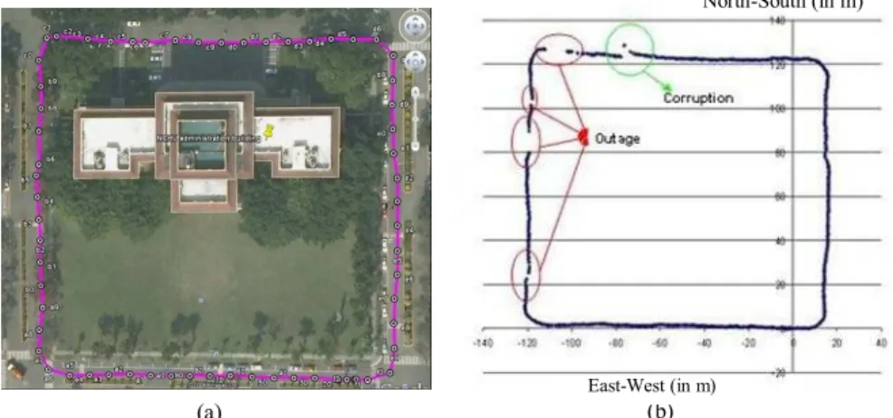
Application of the global positioning system (GPS) to detect and track an object on the earth has been widely developed and applied in several fields such as transportation, surveying, agriculture, natural resources and the environment. In agricultural tasks, GPS is very useful for several applications, especially precision farming in which an autonomous vehicle is navigated and guided [1-7]. The application of GPS in agriculture can improve production because an autonomous system is applied instead of human labour. However, the current application of GPS in an orchard farm is limited by the shading effects of natural obstructors such as trees, which can lead to loss of satellite signals from the sky. Current studies on positioning systems for orchard fields are rare and despite the many applications of GPS for outdoor localisation within an accuracy of 5-10 m during travel, this level of accuracy is not adequate for navigation in an orchard.
Recently, differential GPS (DGPS) has made localisation possible in an outdoor environment (open field) within centimetres. However, current papers addressing movement measurements by DGPS have demonstrated the loss of signal due to shading effects from tree canopies [2, 8-10]. The range in error measurement by DGPS tends to be larger if the location of the receiver is near a building or under trees [10-11]. In fact, DGPS signals are biased and corrupted when the signals from satellites in the field of view are not adequate, which causes multi-path error. If fewer than six satellites are available because the rest are obscured by buildings or trees, the error is greater than 30 cm, which is the limitation of DGPS [9]. In other words, the number of fewer than six satellites leads to greater bias, which causes data to fluctuate from the trend line.
Figure 1. (a) DGPS observation data for a moving route test with tree bushes; (b) lack of data (outage) and corrupted positioning data from an inadequate number of satellites in view
MATERIALS AND METHODS
Differential GPS (DGPS)
DGPS was developed by combining a Trimble DSM 232-DGPS device, a DSM 232 receiver and an antenna-GPS/Beacon DSM132 (Trimble companies, USA) to act as the positioning sensors. The DGPS vehicle position was determined in real time with high accuracy. The DPGS error was less than 25 cm at the best-performing condition, as corrected by the satellite-based augmentation systems (SBAS), when more than six available satellites and a horizontal dilution of precision (HDOP) of less than three occurred. The data from the positioning sensor (DGPS) were obtained from the satellites as NMEA-0183 messages (National Marine Electronic Association), which received real-time corrections of positional data from the Tianda Shan station or Zhenhai Jiao station in Fujian, China. The data consisted of the latitude, longitude and ground speed with respect to a WGS-84 geographic coordinate system and were presented in GGA messages (GPS fix data), and velocity true ground (VTG) messages were presented as NMEA-0183. The DGPS functioned as the primary error eliminator for errors caused by shade from bushes. The signal error was further
reduced by the custom-designed DSM 132 receiver. However, the multi-path error remained due to reflection from the environmental obstructors, which could be corrected using the proposed algorithm to determine the position.
Heading System
The use of DEC sensors developed by Compass Point V2Xe (Parallax, Inc., Taiwan) to construct a compass system to determine the direction of the heading angle of a vehicle was performed by referring to the horizontal x-axis as the direction of the magnetic northern pole and the horizontal y-axis as the east. The DEC signals experienced interference from both the static magnetic field generated by operating the instrument and the environmental magnetic field as well as time interferences caused by sensor offset, scale mismatch and misalignment. These errors were corrected by centring the coordinate origin using one-turn rotation (OTR) scheme [14]. The scheme is a
(b)
East-West (in m)
North-South (in m)
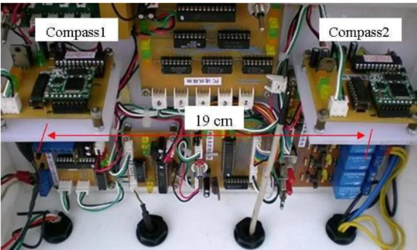
traditional method used to compensate for magnetic interference which originates from changes in the radius and shifts in the centre of the magnetism circle, depending on the ambient environment of the sensor [12-13, 15-16]. The heading system also experienced time-varying errors caused by dynamic external interference including terrain road slope and tilt as well as movement during driving. Among the various external interferences, high-frequency interferences could be eliminated by a predictive calibration algorithm proposed by Lee et al. and Li et al [12-13]. Figure 2 shows a module containing the designed DEC. Two electric compasses were installed parallel to each other 19 cm apart. Output of the double electric compass was transmitted to a receiver board at a rate of 19200 bps using a frequency of 10 Hz. The external interference field and calibration algorithm were further processed using Microsoft Visual Basic 2008®.
Figure 2. Double electric compass
Vehicle Platform and Location of Experiment
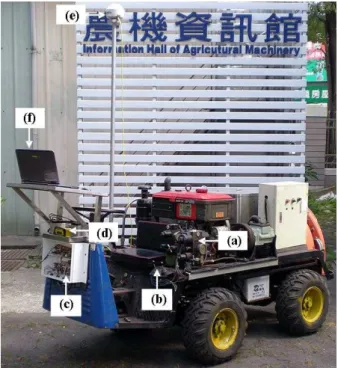
The tested vehicle was a mini-four-wheel sprayer designed for an outdoor orchard and shown in Figure 3. The vehicle was controlled by a hydraulic system (a) through joysticks (b).The heading sensor was mounted in a box in front of the sprayer (c) and the DGPS receiver was mounted above a box (d). An antenna was placed on the vehicle 250 cm above ground level and offset from the centre of the sprayer on the x-axis at 30 cm and y-axis at 60 cm (e). The main electronic-circuit receiver board and the controller board were also mounted in the box in front of the sprayer. All output data from the DGPS and heading sensor were sampled and transmitted at 10 Hz to the receiver board and sent to a laptop computer (f) at a rate of 19200 bps via an RS232 port.
Figure 3. Mini-four-wheel sprayer: (a) vehicle hydraulic control system; (b) joysticks; (c) heading sensor and receiver board; (d) DGPS receiver; (e) DGPS antenna; and (f) laptop computer
Positioning System
Figure 4 illustrates the integrated positioning system algorithm using the coupled DGPS-DEC to calculate real-time vehicle positions. The DGPS-DEC receiver obtains positional data (latitude, longitude, speed, number of satellites, HDOP) and magnetic field values and sends them to a computer. The positioning software converts the positional coordinates in latitude and longitude into the universal transverse Mercator (UTM) coordinate system as proposed by Snyder [17]. Our system automatically uses the predictive algorithm to estimate the vehicle position, even under inappropriate conditions as the DGPS is working, or multi-path error detected by the DGPS. Thus, it can estimate the current position of a vehicle in real time.
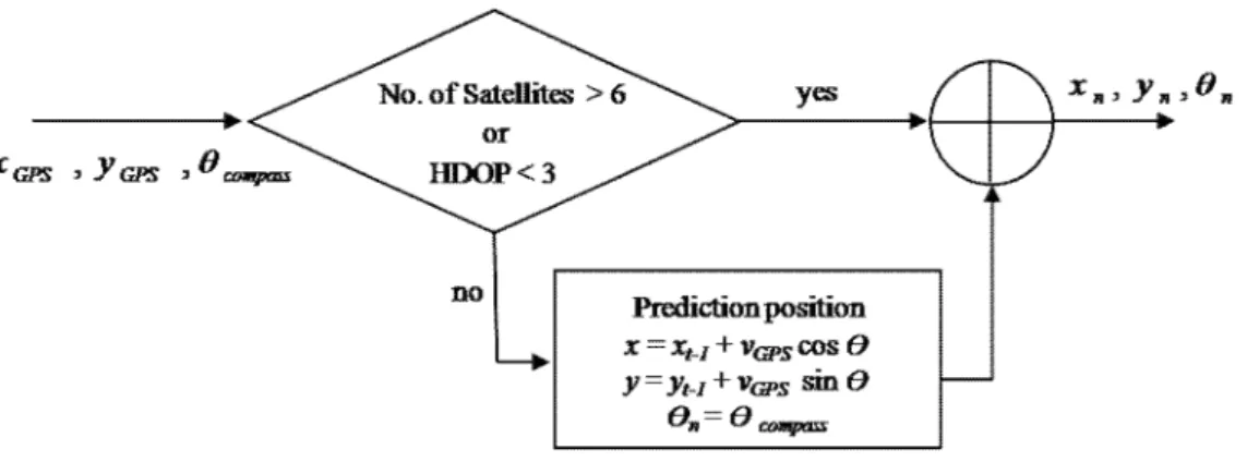
Position Predictive Algorithm
A predictive algorithm is a dynamic model used to solve problems in multi-path error situations when the DGPS receiver is working in problematic conditions, as for instance, when the number of signals from satellites is less than six or the value of HDOP is greater than three. The principle of the predictive algorithm is to use both the heading angle values obtained from a DEC and the latest vehicle velocity values from the DGPS receiver to estimate the new position. The estimated data replace the measurement of the positional error in real time. Figure 5 represents a predictive platform flow diagram. The input is xGPS and yGPS for the current x and y coordinates on the
operation field, and θcompass for the heading angle obtained from DEC at time t. Two algorithm
Figure 4. Overall structure of the positioning system
Figure 5. Predictive platform box diagram
accepted as the correct position coordinates for the current time t. Otherwise, they will be applied to the position predicting equations to obtain the final correct position coordinates. For the position predicting equations, the xt-1 and yt-1 values are the latest vehicle position coordinates detected by the
receiver, vGPS is a vector that describes the most recent vehicle ground speed (m/s) obtained from the
One-turn Rotation (OTR) Scheme
The OTR scheme is a method widely used to compensate the magnetic interferences. Two types of magnetic interferences are: (1) the time invariant originating from change in the radius of the magnetism circle, and (2) the time varying caused by shifts in the centre of the magnetism circle, depending on the ambient environment of the sensor [12-15]. For the OTR scheme, the high-frequency interference technique is employed to overcome the effects of road slope and tilt.
The OTR scheme for the DEC sensor was rotated by 360о (full turn) on the horizontal plane
without any interference. Following the guidelines suggested by Lenz [14], the sensor output was recorded as a reference magnetism circle and was referred by a reference radius (Vref). The sprayer
was then rotated by 360о after the sensor installation. The coefficients V
x,max, Vx,min, Vy,max and Vy,min
were measured and used to calculate the coefficients Vr, Vx,sf, Vy,sf, Vx,off and Vy,off. The threshold value
for the magnetism-circle error (ε), that for the azimuth angle error (γ) and that for slope and tilt (δ) were estimated by considering the environment and error tolerance range for a specific application, which can be optimally adjusted through experiments.
Softwares
All of the algorithms developed were implemented with Microsoft Visual Basic 2008 under Windows XP. The real-time positioning software was developed specifically for an agricultural vehicle working in an orchard environment. For the experimental procedure in the software, the necessary input data were obtained from DGPS and DEC. The software was run by following the algorithm as shown in Figure 4. The calculation of the vehicle’s coordinates under the terms of DGPS multi-path error was then executed. The calculating function for the vehicle positions worked automatically in real time.
RESULTS AND DISCUSSION
Elimination of Electric Compass Interference
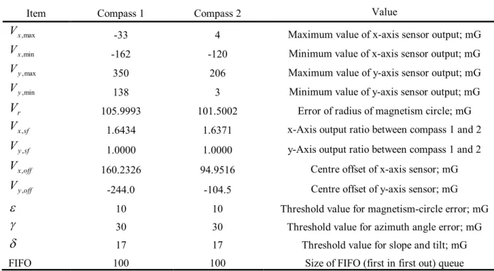
A number of tests were performed to verify the performance of the OTR scheme with respect to compensation for the magnetic interference (time invariant) while the radius changes and shifts of the centre of the magnetism circle depended on the sensor location. The interference caused by the slope and tilt was compensated for by measuring the external interference field and using the calibration algorithm proposed by Lee et al [12]. These methods were used to find the appropriate coefficient values for our sensor, which included the threshold value for the magnetism-circle error (ε), that for the azimuth angle error (γ) and that for slope and tilt (δ). The results of the OTR compensation and coefficient setting are shown in Table 1, which shows all the essential coefficients used for measuring the external interference field and for calibrating electrical compasses 1 and 2.
Table 1. OTR results and coefficients of compasses 1 and 2
The calibration of our DEC installed on the vehicle was completed to confirm the heading and heading angle error (Figure 6). Figure 6(a) shows a practical magnetism circle obtained from the DEC as it is rotated by 360 degrees. The dark blue circle and the red circle represent the raw data (magnetism values) measured by electric compasses 1 and 2 respectively. Both circles are shifted and shrunk because of the effects of the vehicle body. The pink and blue plots show the estimated magnetism values; the circles are shifted to the origin and are also modified to compensate for the interference caused by the slope and tilt. Figure 6(b) illustrates the results of the heading angle measured by electric compasses 1 and 2 with an external interference model for the DEC [12].
The combinations of the heading angle errors in the two compasses in the DEC at the external interference nearly matched the linear cycles with very small disturbance. Figure 6(c) is a plot of the errors in our heading estimation when the vehicle was driven from east to west. It shows that the heading error is always within0.3 degree. Lee et al. [12] reported heading errors within
0.5 degree.
Vehicle Position Estimated by the Positioning System
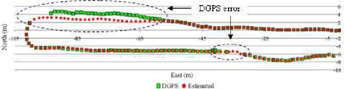
Figure 7 shows the tracks of the vehicle: the green square plot illustrates the position measured by the DGPS with errors while the red plot illustrates the estimated and corrected position using our positioning algorithm. The circled portions in Figure 7 demonstrate that while DGPS working was not in the optimal conditions, our system correctly estimated the vehicle position by using the latest vehicle velocity values and the heading angle at that moment to calculate the new position. Both input values were apparently more reliable than the values obtained by DGPS and gave a smoother track without outage, bias or corruption errors.
Item Compass 1 Compass 2 Value
max ,
x
V -33 4 Maximum value of x-axis sensor output; mG
min ,
x
V -162 -120 Minimum value of x-axis sensor output; mG
max ,
y
V 350 206 Maximum value of y-axis sensor output; mG
min ,
y
V 138 3 Minimum value of y-axis sensor output; mG
r
V 105.9993 101.5002 Error of radius of magnetism circle; mG
sf x
V , 1.6434 1.6371 x-Axis output ratio between compass 1 and 2
sf y
V , 1.0000 1.0000 y-Axis output ratio between compass 1 and 2
off x
V , 160.2326 94.9516 Centre offset of x-axis sensor; mG
off y
V , -244.0 -104.5 Centre offset of y-axis sensor; mG
10 10 Threshold value for magnetism-circle error;mG
30 30 Threshold value for azimuth angle error; mG
17 17 Threshold value for slope and tilt; mG
FIFO 100 100 Size of FIFO (first in first out)queue
Figure 6. Measurement results: (a) angle measurement of external interference field and calibration function; (b) heading angles; and (c) heading angle errors on path
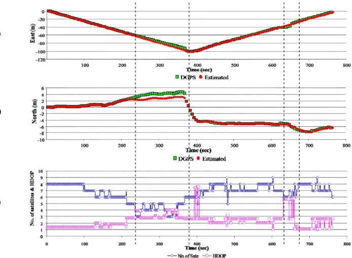
Figures 8(a) and 8(b) show the position plots on the x-axis and y-axis vs. time respectively, while Figure 8(c) compares the number of satellites used and the HDOP values vs. time. Since the vehicle was driven at low speed (0.24 km/hr), the positioning error was expected to be small or insignificant. The error mainly stemmed from the inadequate number of satellites and the high value of HDOP. Significant errors can be observed at 230-370 seconds and 620-660 seconds consistently in Figures 9(a) and 9(b). The DGPS error increased when fewer than six satellites were used and the HDOP value was greater than three. Nevertheless, our estimation using the latest corrected DGPS system was capable of keeping track on the right position for the vehicle.
(a)
(b)
(c)
Figure 8.
Plot of coordinate positions by DGPS (green squares) and combined DGPS-DEC positioning system (red circles) on the x-axis (a) and the y-axis (b), and number of satellites used (blue strip) and HDOP value (pink strip) (c)
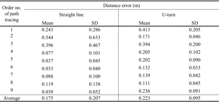
had an average SD of 20.7 cm and an average distance error of 17.5 cm. For the U-turn path, the figures were 9.5 cm and 22.3 cm respectively. The reason for a narrower SD obtained in the case of the U-turn was probably due to is the shorter distance in the experiment, hence a smaller number of observed data, providing more chance of higher accuracy. For the case of the straight route with much longer observed distance, more variation of data was expected, resulting in a higher SD value.
Table 2. Results of distance errors
CONCLUSIONS
A positioning system that corrects the multi-path error to improve the performance of an orchard vehicle has been developed. In particular, the shading effects of natural obstructors and the effects of fewer than 6 satellites and of HDOP value being greater than 3 were addressed. By combining data from both the DGPS and the DEC to predict the position coordinates during movement in real time, we could overcome the problems of DGPS multi-path error using our predictive algorithm. Results have shown that our system has the ability to continue to estimate the vehicle position in real time smoothly (stably) and reliably. Our positioning system should thus be suitable for further development into a guidance control system for autonomous orchard vehicles.
ACKNOWLEDGEMENTS
This work was financially supported by the Agriculture and Food Agency, Council of Agriculture, Executive Yuan of Taiwan and Taiwan scholarship.
Order no. of path tracing
Distance error (m)
Straight line U-turn
Mean SD Mean SD
1 0.243 0.286 0.413 0.205
2 0.544 0.633 0.171 0.046
3 0.396 0.467 0.394 0.200
4 0.077 0.101 0.205 0.102
5 0.037 0.045 0.202 0.090
6 0.033 0.040 0.132 0.033
7 0.088 0.100 0.139 0.042
8 0.119 0.138 0.111 0.045
9 0.039 0.052 0.236 0.091
REFERENCES
1. O. C. Barawid Jr., A. Mizushima, K. Ishii and N. Noguchi, “Development of an autonomous navigation system using a two-dimensional laser scanner in an orchard application”, Biosyst. Eng., 2007, 96, 139-149.
2. J. N. Wilson, “Guidance of agricultural vehicles_a historical perspective”, Comp. Electron.
Agric., 2000, 25, 3-9.
3. T. Bell, “Automatic tractor guidance using carrier-phase differential GPS”, Comp. Electron. Agric., 2000, 25, 53-66.
4. T. Torii, “Research in autonomous agriculture vehicles in Japan”, Comp. Electron. Agric., 2000, 25, 133-153.
5. J. F. Reid, Q. Zhang, N. Noguchi and M. Dickson, “Agricultural automatic guidance research in north America”, Comp. Electron. Agric., 2000, 25, 155-167.
6. R. Keicher and H. Seufert, “Automatic guidance for agricultural vehicles in Europe”, Comp. Electron. Agric., 2000, 25, 169-194.
7. J. Yosida, “A study on the automatic farm machine system for rice”, Comp. Electron. Agric.,
2000, 25, 133-153.
8. Y. Morales and T. Tsubouchi, “DGPS, RTK-GPS and StarFire DGPS performance under tree shading environments”, Proceedings of IEEE International Conference on Integration Technology, 2007, Shenzhen, China, pp.519-524.
9. S. Rezaei and R. Sengupta, “Kalman filter-based integration of DGPS and vehicle sensor for localization”, Trans. Control Syst. Technol., 2007, 15, 1080-1088.
10. K. Ohno, T. Tsubouchi, B. Shigematsu, S. Maeyama and S. Yuta, “Outdoor navigation of a mobile robot between buildings based on DGPS and odometry data fusion”, Proceedings of the International Conference on Robotics and Automation, 2003, Taipei, Taiwan, pp.1978-1984. 11. K. Ohno, T. Tsubouchi and S. Yuta, “Outdoor map building based on odometry and RTK-GPS
positioning fusion”, Proceedings of the International Conference on Robotics and Automation,
2004, New Orleans, LA, USA, pp.684-690.
12. K. M. Lee, Y. H. Kim, J. M. Yun and J. M. Lee, “Magnetic-interference-free dual-electric compass”, Sens. Actuators A, 2005, 120, 441-450.
13. X. Li, Q. Zhou., S. Lu and H. Lu, “A new method of double electric compass for localization in automobile navigation”, Proceedings of the IEEE International Conference on Mechatronics and Automation, 2006, Luoyang, China, pp.514-519.
14. J. E. Lenz, “A review of magnetic sensor”, Proceedings of IEEE, 1990, Dayton, OH, USA, pp.973-989.
15. M. J. Caruso, “Applications of magnetoresistive sensor in navigation system”, Sens. Actuators SAE 1997, SP-1220, 15-21.
16. L. Ojeda and J. Borenstein, “Experimental results with the KVHC-100 fluxgate compass in mobile robots”, Proceedings of the IASTED International Conference on Robotics and Applications, 2000, Honolulu, Hawaii, USA, pp.1-7.
17. J. P. Snyder, “Map Projection-A Working Manual”, Paper1395, U.S. Geological Survey (USGS) Professional, Washington, DC, 1987, p.383.