Composite laminates are made of glass woven roving mats of 610gsm, epoxy resin and nano clay which are subjected to projectile impact. Nano clay dispersion is varied from 1% to 5%. Impact tests are conducted in a gas gun setup with a spherical nose cylindrical projectile of diameter 9.5 mm of mass 7.6 g. The energy absorbed by the laminates when subjected to impact loading is studied, the velocity range is below ballistic limit. The effect of nano clay on energy absorption in vibration, delamination and matrix crack is studied for different weight % of nano clay and for different thick' ness values of the laminates. The natural frequencies and damping factors are obtained for the laminates during impact and the effect of nano clay is studied. The results show considerable improvement in energy absorption due to the presence of nano clay
Nanocomposite, impact, vibration, energy dissipation.
!"
Energy absorption due to impact loading has received much attention recently. Application of such materials can be found both in automobile and in military structures. These materials are used increasingly due to their superior strength, light weight and adaptable design. Traditionally, metals have been the most commonly used materials for crashworthy structural applications and impact related problems mainly due to their plastic deformation characteristics that enable them to absorb impact energy in a controlled manner. Unlike metals, polymer composite materials do not typically exhibit plastic deformation, but they are superior to metals for specific energy ab' sorption. Ganeshbabu et al. (2006) and (2007) studied energy absorption of composite materials subjected to heavy mass projectile. Lee et al. (2000) worked on impact energy absorption charac' teristics of fiber composite materials. Abrate (2001) presented theoretical models for impact stu' dies. The models predict the contact force history and the overall deformation of the plate. Expe' rimental investigation on dynamic behavior was carried out by Pintado et al., (2001) for a wide range of impact velocities. Chandra et al. (1999) reviewed the damping of fiber reinforced compo' sites.
#$
$ % %
a
Indian Insititute of Technology Madras, India 1, [email protected]
b
Indian Insititute of Technology Madras, India 2, [email protected]
http://dx.doi.org/10.1590/1679'78251703
It has been established in recent years that polymer based composites reinforced with small percentage of nano scale fillers can significantly improve mechanical, thermal and barrier proper' ties of pure polymer matrix. Bourbigot et al. (2003), Chen (2004), Gouliang et al.(2008), Korn' mann et al. (2005) and Wu et al. (2002) studied effect of nano particles dispersión in the matrix system to enhance the mechnaical properties of composties. Wetzela et al. (2003) studied that the addition of nano phase particles in fiber reinforced plastics have also yielded improvement in im' pact and other mechanical properties of laminates. Moreover these improvements are achieved through conventional processing techniques without any detrimental effect on processing, appea' rance, density and ageing performance of matrix. Therefore these composites are now considered for different applications in automotive and aerospace industry. When the dimensions of the rein' forcement fibers or particles approach the nanometer scale, number of parameters causing the properties of the corresponding composites are different from those of composites reinforced with macro'scale particles. The main factors affecting the properties of nanocomposites include nano filler dispersion, dimensions, weight fraction, the nature of the matrix material, the interfacial characteristics between nano filler and matrix and the manufacturing process. Mohan et al. (2006) have observed maximum increase in tensile strength, for 2'3 weight % of nano clay compo' sites when compared to composites without clay. In another study by Mohan et al. (2006), nano size organo clay (OC) is compared with unmodified clay (UC), for dynamic mechanical analysis (DMA) and thermo gravimetric analysis (TGA). Results show that the addition of OC increases the thermal properties of epoxy/glass fiber more than that of UC filled composites. Chndradass et al. (2007) observed that dispersion of nano clay effectively improves the internal damping of the composites. Della and Shu (2007) reviewed free vibration of composites with delamination. Avila et al. (2006) studied how nano particles provide better inter phase strength which affects the damping characteristics of composites. In another work, Avila et al. (2011) has proved that the addition of nanoclay and graphene nano sheets to fiberglass/epoxy laminates has not only increa' sed the high velocity impact resistance of these composites, but it also has a major influence on their failure mechanism. Our previous studies, Velmurugan and Balaganesan (2013) and (2014), focused on experiments and analytical model on energy absorption of nanocomposites laminates subjected to impact loading above ballistic limits. It is observed that the presence of clay enhan' ces the energy absorbing capacity of the laminates during perforation. There are limited studies on impact energy absorption of nano composites for below ballistic impact loading. When subjec' ted to impact loading which is below ballistic, which may not completely damage the structure, most of the energy is absorbed in vibration in addition to some micro cracks and delamination.
& '( ) *
&$ (
Dispersion of nano inclusions in the matrix is a v of nanocomposites. In this work, the nanocompos Clay was dispersed in the resin using shear mixer oven to remove the air bubbles at room temperat ne Tetra Amine (TETA) of 10% was mixed with typical results obtained from XRD tests for nano The results obtained are analyzed using Bragg’ peak is the indication for presence of clay in out dispersed into the resin, the reflection peak typical The lower the angle and the intensity peak, the inter gallery spacing of the clay. The improvemen ties are dependent on the amount of intercalation in gallery spacing is a direct indication of an incr Figure 1, single peak at 11.15° for nano clay and c Bragg’s law is 11.8 Å. It is observed that the bas epoxy with clay up to 4%. This reveals that the i ans that Bragg’s diffraction condition is not satis formed (Carrado, 2000). Sharp reflection peak is rresponding interlayer distance is 46 Å which ind med. The formation of intercalated structure for mixing of clay and uneven curing in the intergalle composites.
XRD pattern of clay, epoxy with and w
is a very important factor in the mechanical behavior omposite laminates were manufactured in two steps. mixer at 750 RPM for 2hrs and kept in the vacuum perature, for better dispersion. Hardener, Tri Ethyle' with the epoxy'clay mixture, by weight. Fig. 1 shows nano clay, epoxy and epoxy with 1'5 wt. % of clay. g Bragg’s law to calculate the d'spacing. The reflection
in outer gallery of polymer chain. As these clays are typically shifts to a lower angle and reduces intensity. ak, the greater is the d'spacing and hence the greater ovements in thermal, mechanical and shrinkage proper'
alation and exfoliation structure reached. The increase an increase in intercalation or exfoliation structure. In and corresponding interlayer distance calculated from he basal reflection peak is absent for neat epoxy and the interlayer distance is more than 75 Å which me' ot satisfied or exfoliated nano composite structure has
ak is noticed for epoxy with 5% clay at 2.85° and co' ch indicates that intercalated structure has been for' ure for 5% clay content is due to non'homogenious ergallery and extra gallery matrix regions of the nano'
The laminates of 300 mm square were prepared by hand layup technique and then processed in compression molding machine. The laminates were prepared for the thickness of 2 mm, 3 mm and 5mm respectively and these values were obtained by having 3, 5 and 8 number of layers in the laminates, respectively.
&$&
Experiments were performed using the gas gun test setup, which is shown in Figure 2. Plates of required size were clamped at the edges and were subjected to impact loading by cylindrical pro' jectile. Incident velocity was measured by laser diode. Air pressure in the chamber was varied to get different velocities. Chamber air pressure was maintained by using pressure regulator for get' ting consistent velocity. Shock accelerometer of capacity 100k g PCB make, model No. 350B21, was used to measure the response through the Data Acquisition (DAQ) Card [NI'PXI 4472] and the response was recorded on the computer. The accelerometer was fixed at a distance of ¼th length of diagonal, from one of its corner. The cylindrical projectile with spherical nose of diame' ter 9.5 mm of mass 7.6 g was impacted at the centre of the laminates.
Gas gun setup used for Impact loading, Velmurugan and Balaganesan (2011).
&$+
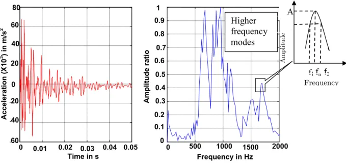
The vibration waveform is composed of a combination of frequency components of different mag' nitudes. In order to extract data that can be analyzed, the time'dependent vibration signal has to be subjected to a spectral analysis, which processes it and separates it into frequency components. The data for these tests is analyzed by performing a Fast Fourier Transform (FFT) on the recor'
Laser diode
ded accelerometer signal. FFT is a discrete digital signal processing technique for converting a time'dependent signal into a frequency spectrum. The spectrum graphs are two'dimensional plots of the spectrum with frequency (Hz) on the horizontal axis and the amplitude of each discrete frequency component on the vertical axis. The amplitude is a peak hold, displaying the maximum amplitude for that particular frequency in the processed time frame.
Figure 3 shows the amplitude response and corresponding frequency response plots for 2 mm thickness laminate with 3% clay when subjected to 35 m/s. The peak mode frequency is 655 Hz for which the amplitude ratio is 1. The maximum energy is dissipated in this frequency. From our previous study on modal analysis, Velmurugan and Balaganesan (2011), it is observed that this range of frequency is its fifth mode of vibration. Also it is observed that 2 mm thickness lamina' tes vibrate in various modes up to 2000 Hz and dissipate the energy received from the projectile.
The damping factor for each mode of the laminate is obtained by using the half power band width method, (see Figure 2).
The following expression is used to find the damping factor ξ.
ξ= f − f
2f 1
Where f2 and f1 are the frequencies and f is the resonance frequency.
: Time response and FFT spectrum for 2 mm thickness laminate with 3% clay subjected to 35 m/s.
! " # $ %&
Higher
frequency
modes
A/√2
A
f1
f
nf
2Frequency
A
m
pl
it
ud
+ #, ** (
The energy dissipated by the laminates subjected to impact loading, for velocities, below ballistic limit, is in the form of vibration, failure of matrix in the delaminated area and delamination. Du' ring impact a localized deformation around the impact region and global deflection away from the point of impact resulting in'plane compression in the front face and tension in the rear face of the laminate, are produced. The deflection of the laminate in the loading direction causes strain in the fibers and matrix. As the velocity of impact is well within ballistic velocity, the strain in the fibers is below the failure strain and within the elastic region. This causes the rebound of the pro' jectile and vibration of the laminate. The stress waves propagate in radial direction. When these stress values exceed the inter laminar shear stress, there is possibility for failure in the matrix and in the lamina interfaces. The first possible failure that occurs in a target is matrix cracking. Ma' trix cracking leads to decrease in inter laminar strength of the composite, as a result further loa' ding causes delamination. The energy dissipated in vibration, delamination and in matrix crack, is discussed in the following sections.
+$
The energy absorbed by the laminates during vibration is calculated based on its total potential energy when subjected to impact loading.
The total potential energy at the initial of vibration is given by the expression,
= (2)
Where, k is stiffness of laminates obtained from static penetration test and x is peak amplitu' de of vibration or deflection at the centre of the laminate which is also the point of impact. The deflection at the centre is obtained from the correlation between the deflection at the location of accelerometer and impact point and the expressions are given in Eqns. (3) to (5).
For 2 mm thickness laminates,
= 3.789 + 0.220 3
In equation (3), is the deflection at the centre and is deflection at the location of acce' lerometer. Similarly the expressions for 3 mm and 5 mm thickness laminates are given in Eqns. (4) and (5), respectively.
For 3 mm thickness laminates,
For 5 mm thickness laminates,
= 3.848 − 0.006 5
The maximum deflection at the location of the accelerometer is calculated from the following expression,
= ! (6)
In the above equation, is the magnitude of maximum acceleration and ! is angular velo' city. Both are obtained from the accelerometer signal and the maximum deflection ( ) is obtai' ned from the above equation.
The total energy of the projectile is given by
"= #$ (7)
Where # is mass of the projectile and $ is velocity of the projectile.
+$&
The area of delamination in the lamínate ( %&' () is measured from the impacted laminates. The
energy due to delamination is given by,
%&' (= %&' ()** (8)
Where )** is critical strain energy release rate in mode II. The strain energy release
te G,,- is calculated from the three point bending test of End Notched Flexural (ENF) specimen (Morrais, 2004). The following equation is used to calculate the )**.values for nanocomposite spe' cimens from the load'deflection results obtained from three point bending test.
)**. =
/ 01
2 345 4 9
Where is notch length, is load, is deflection, is width of the specimen and is the half the length between supports.
+$+ ) - " .
The area undergoing matrix crack is same as delamination area and hence energy due to matrix crack is given by,
Where, (6 is energy absorbed by matrix cracking per unit volume calculated from load'
displacement curves of tensile test results of neat epoxy and clay dispersed epoxy specimens, ℎ is thickness of the laminate and :(is the volume fraction of the matrix.
/ *! * *"!**
/$ 0 % 1%
Tests were conducted for the velocities ranging between 35 m/s and 82 m/s. The results for lami' nates of 2 mm, 3 mm and 5mm thickness are discussed. From FFT spectrum, it is understood that the projectile impact induces the laminate to vibrate in different modal frequencies.
The natural frequency of the 2 mm thickness laminates is shown in Table 1 for velocities from 35 m/s to 82m/s. The frequency values are given for mode V to mode VIII. It is observed that as the velocity of impact increases the frequency values decrease for all the modes when compared to pre impacted laminate frequency values. The laminate without clay when subjected 82 m/s the de' crease in mode V natural frequency is 20% when compared to pre impacted laminate. For the same impact velocity, the decrease in mode V natural frequency of the laminate with 3% clay is 10% when compared that of pre impacted laminate. The laminate with 5% clay has also show 10% less than that of pre impacted laminate. This is due to decrease in damage in the laminates with clay. The same trend is observed in all other modes of 2 mm thickness laminates.
Clay % Velocity of impact in m/s
Frequency of vibration (Hz)
Mode V Mode VI Mode VII Mode VIII
Without clay
Impulse hammer 645 872 998 1181
35 m/s 604 860 967 1157
50 m/s 589 819 959 1138
65 m/s 573 778 951 1129
82 m/s 523 759 916 1108
1% clay
Impulse hammer 665 908 1172 1233
35 m/s 613 897 1148 1340
50 m/s 588 875 1056 1234
65 m/s 582 856 1035 1221
82 m/s 578 792 1017 1155
2% clay
Impulse hammer 699 919 1206 1417
35 m/s 632 906 1188 1442
50 m/s 606 857 1092 1295
65 m/s 597 851 1052 1272
82 m/s 602 799 1026 1231
3% clay
Impulse hammer 711 937 1291 1544
35 m/s 655 897 1259 1540
50 m/s 650 836 1127 1365
65 m/s 642 828 1096 1334
82 m/s 640 820 1059 1336
4% clay
Impulse hammer 718 938 1340 1562
35 m/s 657 902 1262 1541
50 m/s 659 842 1137 1376
65 m/s 652 832 1099 1339
82 m/s 644 818 1053 1338
5% clay
Impulse hammer 727 943 1378 1599
35 m/s 668 899 1272 1548
50 m/s 665 845 1138 1376
65 m/s 661 834 1112 1348
82 m/s 652 823 1067 1337
Clay % Velocity of impact in m/s
Frequency of vibration (Hz)
Mode IV Mode V Mode VI Mode VII
Without clay
Impulse hammer 878 1208 1613 2124
35 m/s 767 1172 1586 2098
50 m/s 725 1114 1551 2071
65 m/s 696 1086 1492 2049
82 m/s 684 1020 1373 1976
1% clay
Impulse hammer 887 1242 1656 2177
35 m/s 848 1215 1619 2138
50 m/s 832 1164 1587 2102
65 m/s 815 1136 1538 2098
82 m/s 749 1043 1419 2057
2% clay
Impulse hammer 917 1288 1692 2198
35 m/s 893 1255 1629 2194
50 m/s 864 1204 1602 2122
65 m/s 836 1161 1555 2102
82 m/s 782 1092 1491 2088
3% clay
Impulse hammer 986 1331 1723 2272
35 m/s 944 1280 1637 2226
50 m/s 893 1259 1614 2157
65 m/s 867 1185 1590 2118
82 m/s 850 1147 1536 2104
4% clay
Impulse hammer 990 1343 1741 2278
35 m/s 949 1288 1686 2236
50 m/s 898 1267 1686 2157
65 m/s 873 1196 1602 2123
82 m/s 858 1159 1582 2112
5% clay
Impulse hammer 991 1362 1775 2284
35 m/s 957 1295 1739 2238
50 m/s 908 1268 1728 2159
65 m/s 889 1226 1679 2127
82 m/s 864 1202 1614 2117
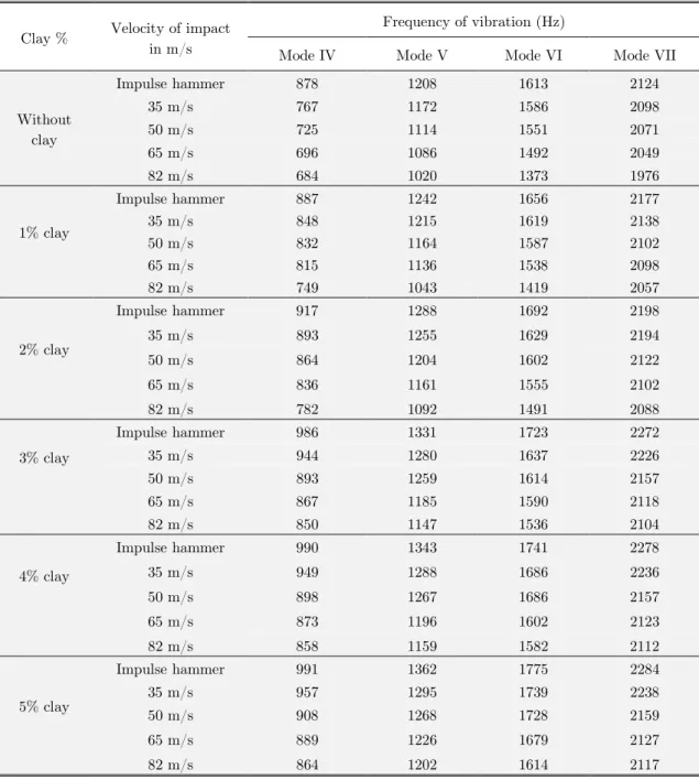
! " Modal frequency of 3 mm thickness laminates for different velocities
ding decrease in percentage values for the laminates with 1% clay are 5.9%, 6.4%, 7.7% and 8.1% respectively. For the laminate with 5% clay, the values are less by 3.2%, 3.3%, 4.1% and 4.4% respectively. The laminate with 5% clay shows less percentage of decrease in frequency values when compared to pre impact values. This is due to dispersion of clay in the 5 mm thickness la' minates that controls the damage due to delamination. In general it is understood that the addi' tion of clay in the matrix increases the natural frequency of vibration due to increase in modulus of nanocomposites. In our previous study, Velmurugan and Balaganesan (2011), increase in tensile modulus was observed in nanocomposite specimens when compared to specimens without clay.
Clay % Velocity of impact in m/s
Frequency of vibration (Hz)
Mode I Mode II Mode III Mode IV
Without clay
Impulse hammer 329 661 990 1201
35 m/s 328 660 946 1111
50 m/s 327 659 945 1106
65 m/s 326 655 935 1095
82 m/s 311 626 890 1046
1% clay
Impulse hammer 336 675 1012 1230
35 m/s 334 672 963 1157
50 m/s 332 668 1291 1151
65 m/s 330 663 1280 1135
82 m/s 329 662 942 1130
2% clay
Impulse hammer 344 697 1064 1281
35 m/s 339 693 994 1209
50 m/s 344 701 990 1171
65 m/s 339 682 988 1188
82 m/s 332 681 962 1192
3% clay
Impulse hammer 357 718 1075 1307
35 m/s 355 713 1022 1228
50 m/s 354 712 1016 1225
65 m/s 351 707 1006 1227
82 m/s 350 703 1001 1220
4% clay
Impulse hammer 360 722 1082 1319
35 m/s 359 717 1034 1267
50 m/s 356 714 1029 1254
65 m/s 355 712 1024 1242
82 m/s 355 709 1021 1232
5% clay
Impulse hammer 362 728 1091 1327
35 m/s 362 727 1068 1285
50 m/s 362 727 1064 1282
65 m/s 361 727 1063 1273
82 m/s 359 721 1052 1268
/$& 2
The damping factors of the impacted specimens are obtained by half power band width technique from FRF plots. The damping factor is obtained for the frequency mode at which maximum energy is dissipated. Figures 3 to 5 correspond to impact damping factor values for laminates of 2 mm, 3 mm and 5 mm thickness values with and without clay, respectively. From these figures, it is clear that as the clay content is increased, there is increase in damping factor which is due to the presence of the additional medium (clay) in the laminate. It is also seen in laminates without clay that as the input velocity increases damping factor increases. This is due to the fact that as the velocity increases the delamination area increases. Laminates of 2mm thickness dissipates maximum energy for the frequency in the range of 600 Hz to 700 Hz for the velocities from 35 m/s to 82 m/s depending upon clay content. From FFT, it is observed that this range of frequen' cy corresponds to its fifth mode of vibration and the damping factor is obtained for this mode. When laminates of 3 mm thickness are subjected to the same range of impact velocities, the peak amplitude is observed in its fourth mode of vibration. This is in the range of 900 Hz to 1000 Hz and the maximum energy is dissipated in this mode. When 5 mm thickness laminates are subjec' ted to impact, the peak amplitude occurs in its third mode of vibration for 35 m/s velocity. For velocities 50 m/s, 65m/s and 82 m/s the peak amplitude occurs in its fourth mode of vibration. Hence it is clear that as the input energy is high the peak amplitude of vibration occurs at higher modes of vibration.
The damping factor values are between 0.02 to 0.08 for all laminates with and without clay and for different modes of vibration. Since most of the energy is dissipated in the peak amplitude, this value is considered for reference and this value is 1 in FFT, the damping factor correspon' ding to this mode is considered and compared. Figure 4 shows damping factor for the 2 mmthick' ness laminates subjected to impact loading. At impact velocity 35 m/s the damping factor for laminate without clay is 0.02 and for the laminate with 5% clay the damping factor is 0.07. The damping factor is increased by a factor of 3. When the laminates without clay are subjected to velocities 50 m/s, 65 m/s and 82 m/s the corresponding damping factor values are 0.03, 0.05. and 0.05 respectively. When the lamintes with 5% clay are subjected to the same velocities the impro' vement in damping factor is about two times. The increase in damping factor is observed in the laminates with clay up to 5%. Rate of increase in damping factor is high in laminates withclay up to 2% dispersion.
75% when compared to laminate without clay. The improvent of damping factor is between 67% to 100% when these laminates with 3% clay are subjected to the velocitiesranging from 35 m/s to 82 m/s.
# Damping factor for 2 mm thickness laminates subjected to impact loading.
: Damping factor for 3 mm thickness laminates subjected to impact loading.
Among the 2 mm, 3 mm and 5 mm thickness laminates, 2 mm thickness laminates show high improvement in damping factor due to the presence of clay. There is an improvement in dam' ping factor in laminates of thickness values 3 mm and 5 mm as the impact velocity increases. Energy dissipation occurs when interfacial slip of nano scale fillers is activated in host matrix material, which leads to improvement in damping factor. For rigid nano'particles, the high stress area around the particles will lead to initial microcracks and inelastic deformation in the matrix. The interfacial shear strength between nano'filler and matrix is higher than that in conventional
0 10 20 30 40 50 60
! "# $# %# &# '#
%' '( )' *$
0 10 20 30 40 50 60 70 80
! "# $# %# &# '#
composites which is due to the formation of cross'links or shield of the nano'fillers and form thic' ker interphases. The nano scale filler in the matrix acts as secondary fiber which enhances the energy absorption of the laminates when subjected to impact loading.
$: Damping factor for 5 mm thickness laminates subjected to impact loading.
/$+ 3 ) - " .
Stiffness of the laminates is calculated from the slope of load displacement plot obtained in static deflection test% The values of stiffness for the laminates of 2 mm, 3 mm and 5 mm thicknesses are given in Table 4. It is observed that there is increase in stiffness values for laminates with clay up to 3%. The improvement for 2 mm thickness laminate with 3% clay is 16.5% when compared to laminate without clay. Corresponding improvements for 3 mm and 5 mm thickness laminates with 3% clay are 20% and 15% respectively. The laminates with 4% and 5% clay show higher stiffness values with respect to laminates without clay, but less than that of the laminates with 3% clay. The strain energy release rate is calculated from Eq. (9). It is observed that the speci' mens with clay show higher strain energy release rate than the specimen without clay. The values for strain energy release rate and matrix crack energy of epoxy specimens with and without clay are also given in Table 4. The increase in GIIC values is observed for clay up to 5%. The impro' vement for the specimen with 3% clay and 5% is 25% and 26% respectively when compared to specimen without clay. The matrix crack energy is calculated from the stress'strain curve of spe' cimens made epoxy with and without clay. This energy is used to predict matrix crack energy of laminate during impact loading. The specimen with 3% clay shows highest value compared to other specimens.
0 10 20 30 40 50 60
! "# $# %# &# '#
Properties Without clay 1% clay 2% clay 3% clay 4% clay 5% clay
Stiffness, k for 2 mm thickness
lamínate (N/mm) 202.53 211.49 216.67 235.89 219.15 221.18
Stiffness, k for 3 mm thickness
lamínate (N/mm) 297.10 336.08 352.47 356.42 328.3 299.74 Stiffness, k for 5 mm thickness
lamínate (N/mm) 505.11 506.63 519.32 579.20 523.10 521.51
Strain Energy release rate,
GIIC (kJ/m3) 2.31 2.48 2.75 2.88 2.91 2.92
Matrix crack Energy, Emt (MJ/m3) 0.906 0.912 0.932 0.939 0.935 0.921
! " # Static deflection test stiffness (k), Strain Energy release rate (GIIC) and Matrix crack Energy, Emt of the laminates with and without clay.
&: Showing the energy absorbed by the 2mm thickness lamínate when subjected to impact velocity 50 m/s.
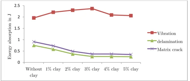
As the velocity of impact increases to 82 m/s, the projectile energy is 25.55 J and the energy ab' sorption in laminate without clay due to vibration is 6.46 J. The increase in energy absorption in vibration is observed in all the cases. The laminate with 3% clay absorbs 9.61 J of energy in vi' bration which is 50% higher than the laminate without clay. This can be seen in Figure 8. The delamination and matrix crack energies are less than the energy absorbed in vibration for the laminates with and without clay. The energy absorbed by delamination and matrix crack for the nanocomposites is less than that of laminate without clay. The delamination energy of laminate with 3% clay is less by 50% of the laminate without clay. The matrix crack energy for laminate with 3% is about 50% less than that in laminate without clay.
Showing the energy absorbed by the 2 mm thickness laminate when subjected to impact velocity 82 m/s. 0 2 4 6 8 10 12 Without clay
1% clay 2% clay 3% clay 4% clay 5% clay
E ne rg y ab so rp ti on i n J Vibration delamination Matrix crack 0 0.5 1 1.5 2 2.5 3 3.5 4 Without clay
1% clay 2% clay 3% clay 4% clay 5% clay
Figures 9 and 10 show the energy absorbed by the 3 mm thickness laminates by vibration, dela' mination and matrix crack for the input projectile energy of 9.5 J and 25.5 J respectively. The vibration energy increases as the % of clay dispersion increases up to 3% and decreases on further increase of clay. This is similar to 2 mm thickness laminates. The maximum energy dissipation in vibration is about 50% higher than the laminate without clay.
: Showing the energy absorbed by the 3mm thickness laminate when subjected to impact velocity 50 m/s.
As the input energy of the laminate increases the energy absorbing capacity of the laminate in vibration also increases. Due to increase in thickness of the laminates, the damage area in delami' nation is less and, hence the energy absorbed in delamination and matrix crack is less when com' pared to 2 mm thickness laminates. Figure 10 shows the energy absorbed by the 3 mm thickness laminates for the input projectile energy of 25.5 J. The energy absorbed in delamination and ma' trix crack is 1 J for the laminates without clay for input energy of 9.5 J and it is about 2 J for input energy of 25.55 J. But in the laminates with clay, the energy due to damage is less by 50% compared to laminate without clay. In nanocomposite laminates, the delamination and matrix crack energies are reduced, further the damage area for 4% and 5% clay dispersion is less. Figure 11 shows the damage area of the laminate when subjected to 50 m/s. It is clear that for the input energy of 9.5 J, there is no damage in the laminate with 5% clay and hence most of the energy is absorbed in vibration mode.
0 0.5 1 1.5 2 2.5 3 3.5 4 4.5 5
Without clay
1% clay 2% clay 3% clay 4% clay 5% clay
E
ne
rg
y
ab
so
rp
ti
on
i
n
J
Showing the energy absorbed by the 3mm thickness laminate when subjected to impact velocity 82 m/s.
Showing the area of impact of 2mm thickness glass/epoxy laminate with 5% clay when subjected to 50m/s.
Figure 12 shows the energy absorption of the 5 mm thickness laminates when subjected to impact energy of 9.5 J. The energy absorbed in vibration is similar to 2 mm and 3 mm thickness lamina' tes. The matrix crack energy is about 20% higher than the delamination energy in all the cases. The same trend is observed for input energy is 25.55 J which is shown in Figure 13.
0 2 4 6 8 10 12
Without clay
1% clay 2% clay 3% clay 4% clay 5% clay
E
ne
rg
y
ab
so
rp
ti
on
i
n
J
Vibration delamination Matrix crack
: Showing the energy absorbed by the 5 mm thickness lamínate when subjected to impact velocity 50 m/s.
As the input energy of the laminate increases the energy absorbing capacity in vibration also in' creases. The laminates without clay absorb more energy in delamination than the composites with clay showing the same trend as other laminates. Among 2 mm, 3 mm and 5 mm thickness lami' nates, 2 mm thickness laminates dissipate more energy at lower velocity of impact, 3 mm and 5 mm thickness laminates dissipate more energy at higher velocity. This is due to increase in stiff' ness of thicker laminates. Thin laminates absorb energy in other failure modes at higher velocity of impact. The delamination and matrix crack energy of 2 mm thickness laminates are higher than 3 mm and 5 mm laminates. The reason is increase in failure area of laminates due to stret' ching of the layers. Laminates of 5 mm thickness absorbs more energy in delamination and matrix crack than 3 mm thickness laminates. This is because of more damage area which is due to in' crease in distance between the mid plane and outer layer.
Figure 14 (a) and (b) show the delamination area of laminates of 5 mm thickness, with and without clay respectively. In the laminate without clay the delamination area is 1256 sq. mm and the corresponding value of laminate with 2 % clay is 491 sq. mm. This shows that the presence of clay decreases the area to almost 1/3rd of the delamination area in laminates without clay. Hence it is understood that addition of clay very much controls the delamination area. This is one of the reasons for the increase in vibration energy of the laminates with clay.
0 0.5 1 1.5 2 2.5
Without clay
1% clay 2% clay 3% clay 4% clay 5% clay
E
ne
rg
y
ab
so
rp
ti
on
i
n
J
: Showing the energy absorbed by the 5 mm thickness lamínate when subjected to impact velocity 82 m/s.
# (a) Showing the delamination area of 5 mm thickness glass/epoxy lamínate without clay when subjected to 82m/s, (b) Showing the delamination area of 5mm thickness
glass/epoxy laminate with 2% clay when subjected to 82m/s.
4$ " " !* *
Laminates of 2 mm, 3 mm and 5 mm thickness were prepared by hand lay'up and compression molding process, and subjected to projectile impact for velocities between 35m/s and 82 m/s in clamped'clamped condition. The frequencies of vibration, damping factor and energy absorbed by the laminates are obtained. The following conclusions are made.
0 2 4 6 8 10
Without clay
1% clay 2% clay 3% clay 4% clay 5% clay
E
ne
rg
y
ab
so
rp
ti
on
i
n
J
Vibration delamination Matrix crack
The increase in frequency of vibration is observed in laminates with clay than laminates wit' hout clay.
Addition of clay improves damping factor in all the laminates irrespective of the velocity of impact.
Presence of nano clay also improves the energy absorption capacity of laminates in vibration. As the velocity increases the energy absorption in vibration mode increases.
Addition of clay controls the energy absorption of laminates in delamination and matrix crack.
.
The authors gratefully acknowledge the support received from Department of Science and Tech' nology, India through Indo – South African collaboration Research project.
Abrate, S. (2001). Modeling of impacts on composite structures, Composite Structures, 51: 129–138.
Avila, A., Neto A. S., H.N. Junior, (2011). Hybrid nanocomposites for mid'range ballistic protection, International Journal of Impact Engineering 38, 669'676.
Avila, A., Duarte H. V., Soares, M. I., (2006). The nano clay influence on impact response of laminated plates Latin American Journal of Solids and Structures 3: 3'20.
Balaganesan, G., Velmurugan, R., Srinivasan, M., Gupta, N. K., Kanny, K. (2014). Energy absorption and ballis' tic limit of nanocomposite laminates subjected to impact loading, International Journal of Impact Engineering 74: 57'66.
Bourbigot. S, Vanderhart, D.L., Gilman, J.W., Awad, W.H., Davis, R.D., Morgan, A.B., (2003). Investigation of nano dispersion in polystyrene–montmorillonite nanocomposites by solid'state NMR, Journal of Polymer Scien' ce Part B: Polymer Physics 41(24): 3188'3213.
Carrado, K.A (2000) Synthetic organo' and polymer'clays: preparation, characterization and Materials applica'
tions. 17: 1'23.
Chandra. R, Singh, S.P., Gupta, K., (1999). Damping studies in fiber'reinforced composites'a review, Composite Structures 46: 41'51.
Chandradass. J, Rameshkumar, M., Velmurugan, R., (2007). Effect of Nano clay addition on vibration properties of glass fiber reinforced vinyl ester composites, Materials letter 61: 4385'4388.
Chen, B., (2004). Polymer–clay nanocomposites: an overview with emphasis on interaction mechanisms, British Ceramics Transactions 103(6): 241–249.
Della, C.N., Shu, D., (2007). Vibration of Delaminated Composite Laminates: A Review, Applied Mechanics Re' views60: 1'20.
Ganeshbabu, M., Velmurugan, R. Gupta, N. K., (2006). Projectile impact on sandwich panels, International Jour' nal of Crashworthiness 11(2): 153'164.
Ganeshbabu, M., Velmurugan, R., Gupta, N. K., (2007). Heavy mass projectile impact on thin and moderately thick unidirectional fiber/epoxy laminates, Latin American journal of solids and structures 4: 247'256.
Kornmann, X., Rees M.,, Thomann, Y., Necola, A., Barbezat, M., Thomann, R., (2005). Epoxy'layered silicate nano composites as matrix in glass fibre'reinforced composites, Composites Science and Technology 65: 2259–2268. Lee, D.G., Lim, T.S., Cheon, S.S., (2000). Impact energy absorption characteristics of composite structures, Composite Structures 50: 381'390.
Mohan, T.P., Ramesh Kumar, M., Velmurugan, R., (2006). Thermal, mechanical and vibration characteristics of epoxy'clay nanocomposites, Journal of Materials Science 41(18): 5915'5925.
Mohan, T.P., Ramesh Kumar, M., Velmurugan, R., (2006). Mechanical and barrier properties of epoxy polymer filled with nanolayered silicate clay particles, Journal of Materials Science 41: 2929'2937.
Morrais, A.B. de. (2004) Analysis of Mode II inter laminar fracture of multidirectional laminates, 35: 51'57.
Pintado, P., Pedraza, C., Del, J.M., Castillo, Benitez, F.G. (2001). Experimental investigation of the dynamic response of graphite'epoxy composite laminates under compression, Composite Structures53: 493–497.
Velmurugan, R., Balaganesan, G., (2013). Energy absorption capability of glass/epoxy nano composite laminates, International Journal of Crashworthiness 18(1): 82'92.
Velmurugan, R., Balaganesan, G., (2011). Modal analysis of pre and post impacted nano composite laminates, Latin American Journal of Solids and Structures 8: 9'26.
Wetzela, B., Frank, H., Ming, Q.Z., (2003). Epoxy nano composites with high mechanical and tribological perfor' mance, Composites Science and Technology 63: 2055–2067.