Pedro André da Silva Corista
Licenciado em Ciências da EngenhariaEletrotécnica e de Computadores
IoT data processing pipeline in FoF
perspective
Dissertação para obtenção do Grau de Mestre em Engenharia Eletrotécnica e de Computadores
Orientador: Ricardo Luís Rosa Jardim Gonçalves, Professor Auxiliar com
Agregação, Faculdade de Ciências e Tecnologia da Universidade
Nova de Lisboa
Co-orientador: João Filipe dos Santos Sarraipa, Investigador, UNINOVA
Júri:
Presidente: [Nome do presidente do júri]
Arguente: [Nome do arguente 1]
Vogais: [Nome do vogal 1]
IoT data processing pipeline in FoF perspective
Copyright © Pedro André da Silva Corista, Faculdade de Ciências e Tecnologia, Universidade
Nova de Lisboa.
A Faculdade de Ciências e Tecnologia e a Universidade Nova de Lisboa têm o direito,
perpétuo e sem limites geográficos, de arquivar e publicar esta dissertação através de
exemplares impressos reproduzidos em papel ou de forma digital, ou por qualquer outro
meio conhecido ou que venha a ser inventado, e de a divulgar através de repositórios
científicos e de admitir a sua cópia e distribuição com objetivos educacionais ou de
Acknowledgements
After an intense period of academic formation, I want to greet all the people that helped and
supported me during this time, and that in their own way, contributed to this dissertation.
I would first like to thank my family, specially my parents and brother for the constant support
that provided me, either in the good or hard academic times. The motivation that they
provided granted me the confidence to grow further.
To my advisor, Dr. Ricardo Gonçalves and my co-advisor Dr. João Sarraipa for giving me the
opportunity of working in a GRIS’s project and for believing in me and in my capabilities. The door to João’s office was always open whenever I had a question about my research, or when
I got lost in the writing process.
To all the people that work at GRIS, for supporting me great and being always willing to help.
The environment and counselling that they provided, enlightened me during several of my
dissertation’s steps.
Finally, I would like to thank all my close friends who have never disappointed me during the
whole period of the dissertation. Special thanks to my friends who used their own time to
Abstract
With the development in the contemporary industry, the concepts of ICT and IoT are gaining more importance, as they are the foundation for the systems of the future. Most of the current solutions converge into transforming the traditional industry in new smart interconnected factories, aware of its context, adaptable to different environments and capable of fully using its resources. However, the full potential for ICT manufacturing has not been achieved, since there is not a universal or standard architecture or model that can be applied to all the existing systems, to tackle the heterogeneity of the existing devices. In a common factory, exists a large amount of information that needs to be processed into the system in order to define event rules accordingly to the related contextual knowledge, to later execute the needed actions. However, this information is sometimes heterogeneous, meaning that it cannot be accessed or understood by the components of the system. This dissertation analyses the existing theories and models that may lead to seamless and homogeneous data exchange and contextual interpretation. A framework based on these theories is proposed in this dissertation, that aims to explore the situational context formalization in order to adequately provide appropriate actions.
Resumo
Com os desenvolvimentos da indústria contemporânea, os conceitos de ICT e IoT estão a ganhar mais importante devido a representarem os alicerces para os sistemas do futuro. Grande número das soluções existentes converge para a transformação da indústria tradicional em novas fábricas inteligentes interconectadas, cientes do seu contexto, adaptáveis a diferentes ambientes e capazes de usar os seus recursos na totalidade. No entanto, o potencial máximo da manufatura ICT ainda não foi atingido, dado que não existe uma arquitetura ou modelo universal ou padrão, que possa ser aplicado a todos os sistemas existentes e que possa lidar com a heterogeneidade dos dispositivos existentes. Numa típica fábrica, existe uma quantidade grande de informação que precisa de ser processada pelo sistema, para que se possa definir regras de eventos de acordo com o conhecimento contextual relativo, para poder posteriormente executar as ações necessárias. No entanto esta informação é, por vezes, heterogénea, o que quer dizer que não pode ser acedida ou percebida pelos componentes do sistema. Esta dissertação analisa as teorias e modelos de informação de harmonização existentes, que podem permitir a troca e interpretação de informação homogénea. Uma framework, baseada nestas teorias, é proposta nesta dissertação, que pretende explorar a formalização do contexto situacional para conseguir providenciar ações apropriadas, de forma adequada.
Table of Contents
Acknowledgements ... vii
Abstract ... ix
Resumo ... xi
Table of Contents ... xiii
List of Figures ... xv
List of Tables ... xvii
Table of Acronym ... xix
1 Introduction ... 1
1.1 MOTIVATION ... 2
1.2 RESEARCH QUESTION ... 3
1.3 HYPOTHESIS... 4
1.4 WORK METHODOLOGY ... 4
1.5 DISSERTATION OUTLINE ... 5
2 State of art ... 7
2.1 FACTORIES OF THE FUTURE ... 7
2.1.1 Concepts of factories of future ... 8
2.1.1.1 Interoperability ... 8
2.1.1.2 Virtualization and Cyber physical systems... 9
2.1.1.3 Decentralization and real-time capability ... 10
2.2 KERNEL ... 10
2.2.1 Processes ... 10
2.2.1.1 Process hierarchy and device management ... 11
2.2.2 Device and drivers management ... 12
2.3 FIWARE, THE EUROPEAN PROJECT ... 13
2.3.1 FIWARE enablers ... 13
2.4 SYSTEM AWARENESS AND DATA HARMONIZATION ... 15
2.4.1 Context models ... 16
2.4.2 Context frameworks ... 17
2.4.3 Situation awareness ... 18
2.4.4 Data harmonization levels... 20
2.4.5 Data harmonization framework ... 21
2.5 STATE OF THE ART CONCLUSIONS ... 22
3 System Architecture ... 25
3.1 SCENARIO... 26
3.2 FRAMEWORK ... 27
3.2.1 Acquisition Layer ... 29
3.2.2 Data harmonization Layer ... 30
3.2.4 Application Layer ... 35
3.3 DATA HARMONIZATION ... 37
3.3.1 Sensor data Mismatches ... 37
3.3.2 Harmonization Guidelines ... 40
3.4 VF-OS PROJECT ... 41
3.4.1 Vf-OS APPS ... 42
3.5 PROPOSED ARCHITECTURE ... 44
3.6 ORION ... 45
3.6.1 REST API... 46
3.7 DOCKER ... 48
4 APPS Development ... 50
4.1 APPLICATIONS OVERVIEW ... 50
4.2 BASIC FUNCTIONS ... 53
4.3 VFAIL ... 54
4.3.1 Acquire Sensor Data ... 55
4.3.2 Process and Harmonize Data ... 56
4.3.3 Evaluate Context ... 57
4.4 VPRODUCTMON ... 58
4.4.1 Display Evaluated Results ... 58
4.4.2 Insert Context ... 59
4.4.3 Insert Rule... 60
4.4.4 Delete Elements and Display elements ... 62
4.4.5 Communicate vFNegotiation ... 64
5 Results and Validation ... 66
5.1 TESTING METHODOLOGY ... 66
5.1.1 Test Control Notation ... 66
5.2 TESTING IMPLEMENTATION ... 68
5.2.1 Framework implementation demonstration ... 68
5.2.2 Framework Test evaluation ... 74
5.2.3 Framework communication demonstration ... 76
5.2.4 Framework communication evaluation... 79
5.3 THESIS VALIDATION ... 80
5.4 SCIENTIFIC AND INDUSTRIAL VALIDATION ... 81
6 Conclusions and Future Work ... 84
6.1 CONCLUSIONS ... 84
6.2 FUTURE WORK ... 85
List of Figures
FIGURE 1-1:INTERCONNECTIVITY IN FACTORIES OF THE FUTURE. ... 1
FIGURE 1-2:MOTIVATION TOPICS ... 3
FIGURE 2-1:CYBER-PHYSICAL SYSTEMS CONCEPT ILLUSTRATION (T.HIGASHINO,2005) ... 9
FIGURE 2-2:KERNEL DRIVER MANAGEMENT ... 12
FIGURE 2-3:FI-PPP ARCHITECTURE(“CORDISARCHIVE :EUROPEAN COMMISSION :CORDIS :FP7 :ICT :NET INNOVATION : FI-PPPCALL 3,”2013). ... 13
FIGURE 2-4:HIERARCHICAL CONTEXT FRAMEWORK(MAMO &EJIGU,2014) ... 17
FIGURE 2-5:THE THREE LEVEL MODULE FOR SITUATION AWARENESS (PANTELI &KIRSCHEN,2015) ... 19
FIGURE 2-6:ACTIVITY THEORY MODEL DIAGRAM (PANTELI &KIRSCHEN,2015) ... 20
FIGURE 2-7:DATA HARMONIZATION PROCESS(WC &CORVE,2015) ... 22
FIGURE 3-1:GLOBAL SCENARIO ... 26
FIGURE 3-2:FRAMEWORK HIGH LEVEL ARCHITECTURE ... 28
FIGURE 3-3: ACQUISITION LAYER BEHAVIOUR ... 30
FIGURE 3-4:KEY PAR VALUES EXAMPLE FROM (SYMPOSIUM ET AL.,2015) ... 31
FIGURE 3-5: XMPP SENSOR RESPONSE ... 31
FIGURE 3-6: DATA HARMONIZATION LAYER BEHAVIOUR ... 32
FIGURE 3-7:CONTEXT,RULES AND READINGS RELATION ... 33
FIGURE 3-8:CONTEXT REASONING LAYER BEHAVIOUR ... 34
FIGURE 3-9:APPLICATION LAYER, INSERT ELEMENTS BEHAVIOUR ... 36
FIGURE 3-10:VF-OS PROJECT OVERVIEW (LEAD,2017) ... 42
FIGURE 3-11:PROPOSED SYSTEM ARCHITECTURE ... 45
FIGURE 3-12:SDN ARCHITECTURE(VELRAJAN,2017) ... 46
FIGURE 3-13:REST APIDESIGN (DZONE,2017) ... 47
FIGURE 3-14:DOCKER ARCHITECTURE(INC,2017) ... 49
FIGURE 4-1:NECESSARY MODULES FOR THE DESCRIBED SCENARIO ... 50
FIGURE 4-2: VFAIL APPLICATION MODEL ... 51
FIGURE 4-3: VPRODUCTMON APPLICATION MODEL ... 52
FIGURE 4-4: ORION CONTEXT ELEMENT RESPONSE (JASON RESPONSE) ... 54
FIGURE 4-5: ACQUIRE SENSOR DATA ACTIVITY PROCESS ... 55
FIGURE 4-6:PROCESS AND HARMONIZE DATA ACTIVITY PROCESS ... 56
FIGURE 4-7:EVALUATE CONTEXT PROCESS ... 57
FIGURE 4-8:DISPLAY EVALUATED RESULTS ACTIVITY PROCESS AND INTERFACE... 59
FIGURE 4-9:INSERT CONTEXT ACTIVITY PROCESS AND INTERFACE ... 60
FIGURE 4-10:INSERT RULE ACTIVITY PROCESS AND INTERFACE ... 61
FIGURE 4-11:DELETE ELEMENT ACTIVITY PROCESS AND INTERFACE ... 63
FIGURE 4-12:DISPLAY ELEMENTS INTERFACE... 64
FIGURE 4-13:COMMUNICATE VFNEGOTIATION ACTIVITY PROCESS AND INTERFACE ... 65
FIGURE 5-1:CONTEXT SUCCESS SUBMISSION(TOP) AND BLANK SPACE WARNING (BOT) ... 69
FIGURE 5-2:SUCCESSFUL INSERTED RULE(LEFT) AND RULE THAT FAILS FOR INEXISTENT CONTEXT(RIGHT) ... 70
FIGURE 5-3:SUCCESSFUL CONTEXT SUBMISSION CONTEXT (LEFT) AND RULE (RIGHT) ... 70
FIGURE 5-4:RESPONSE ON AN INPUT OF AN EXISTING CONTEXT(LEFT) AND SUBMISSION OF ONE OF THAT CONTEXT RULES(RIGHT) ... 71
FIGURE 5-5:CONTEXT AND RULES REGISTERED IN THE SYSTEM ... 72
FIGURE 5-6:EVALUATION RESULTS ... 72
FIGURE 5-7:DELETE A RULE AND A CONTEXT ... 73
FIGURE 5-8:EVALUATION OF A CONTEXT WITH TWO RULES ... 74
FIGURE 5-9:EVALUATION OF A CALIBRATION CONTEXT ... 77
FIGURE 5-11:ERROR MESSAGE RESULTING FROM A FARMER NOT BEING REGISTERED IN THE SYSTEM ... 78
FIGURE 5-12:SUCCESSFUL COMMUNICATION FROM A VERIFIED CONTEXT AND VIEW FROM VORDER SIDE ... 78
FIGURE 5-13:SUCCESSFUL COMMUNICATION FROM A FAILED CONTEXT... 79
List of Tables
TABLE 2-1–KERNEL PROCESS STATES. ... 11
TABLE 3-1–SCENARIO STEPS ... 26
TABLE 3-2–LOSSLESS SENSOR MISMATCHES. ... 38
TABLE 3-3–LOSSY SENSOR MISMATCHES. ... 39
TABLE 3-4–VF-OS USE CASE SCENARIOS ... 43
TABLE 5-1:TTCN EXAMPLE TABLE ... 67
TABLE 5-2:TTCN INSERT RULE TEST ... 75
TABLE 5-3:TTCN EVALUATE SENSOR DATA TEST ... 76
Table of Acronym
Acronyms Definition
API Application Programming
Interface
CEP Complex Event Processing
CORBA Common Object Request Broker
Architecture
CPPS Cyber-Physical Production
System
CPS Cyber-Physical System
DB Database
EDA Event-Driven Architecture
EU European Union
FI-PPP Future Internet Private Public
Parcery
FoF Factories of the Future
FP7 Seventh Framework
Programme
GE Generic Enabler
GRIS Group for Research in
Interoperability of Systems
HTTP Hypertext transfer protocol
I2ND Interface to Networks and
Devices
ICT Information and
Communication Tecnologies
ID Identification
Electronics Engineers
IO In Out
IoT Internet Of Things
ISO International Organization for
Standardization
IT Information Tecnology
JSON JavaScript Object Notation
OS Operating System
OWL Web Ontology Language
PIV Process Identification Value
RDF Resource description
framework
RFID Radio-Frequenct Identification
SDN System defined Network
SODA State Of The Art
TSV Tab-separated values
UNINOVA Institute for the development of
new technology
VF Virtual factory
Vf-APPS Virtual-Factory Applications
Vf-MW Virtual-factory Middleware
Vf-SK Virtual-factory System Kernel
1
Introduction
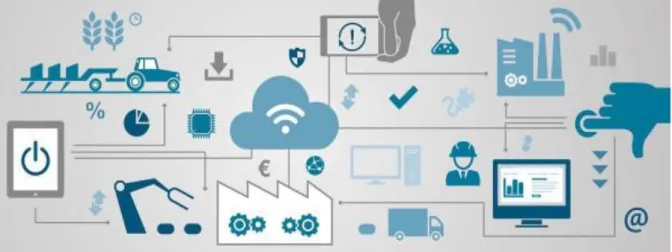
Nowadays world is living the fourth industrial revolution. The previous revolutions introduced the concepts of machinery work, mass production and automation, this one focus on smart machines and interconnectivity. The future industry will tend towards flatter management structures with a more highly skilled and IT literate workforce that will be focused on improving the product’s development and performance. Factories are already applying the concepts of internet of things. This way a “network” can be formed between devices, objects and people that cooperate in order to accomplish common goals.
Figure 1-1: Interconnectivity in factories of the future.
With the development of technology, new forms of agriculture are emerging in our society. The use of technology is growing in order to improve agriculture production and have higher profits. To achieve these goals, agricultural producers or distributors use Information Technology and Communication (ICT) to help to manage agriculture. Sensors can be used to enable real time monitoring food's parameters, such as pH, temperature, earth's moisture or oxygen flow. With these sensors and its connection with the Internet, it is possible to monitor all cultivations, even if they are apart, and predict and control its quality and how much food can be sold. With the knowledge of position, its values and seasonal care, tractors can supply plant's daily needs, without human intervention.
Several plants production is increasingly threatened. Climate changes, insufficient available lands, air toxins are some problems that agriculture faces these days. One agricultural solution to address these problems are plant factories. They can be defined as horticulture greenhouses or automated system facilities that have artificially controlled environments in order to produce vegetables and seedling year-round (Hirama, 2015). By using the benefits of smart farming, it is possible to turn the entire growth process automated and leading economies in order to control cost, quantity and quality against the required harvest time.
This work aims to develop an implementation of the models related to system´s situational awareness and data optimization that can be used within a framework that processes fruit information collected during a harvest process. In this dissertation is proposed the creation of a context framework, that can be used to infer about sensor data, based on context and rules. This dissertation’s implementation will be done according to the needs of a European project called Vf-OS. This project aims to create an open operating system that can be used as a reference, considering Factories of the Future.To achieve this goal will be presented first the research question/hypothesis and the information that allows to contextualize them and present the information that allows to create a model in order to answer them. On a second phase will be presented a model based on the retrieved information that will allow to collect data to verify the hypothesis.
1.1
Motivation
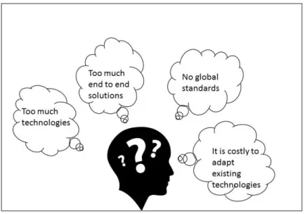
Within factories there are lots of systems and information that must be exchanged or shared among the different blocks. Therefore exists the need of having a platform to manage all the interactions between the systems. However some platforms with this objective already exists in some industrial sectors, there aren´t platforms based on open and transparent standards.
harmonized and consequently are not interoperable. The existing technologies have been created in order to develop point to point solutions that aim to solve or improve the solution to a single problem instead of considering the whole situation or global factory architecture. The main problem of this situation is that not much of the existing solutions can be adapted to different organizations, because they were designed to fit a particular system. This problems within industrial technologies are even more severe in modern agriculture, since this is a fairly new industrial “branch”. Concerning subjects like situational awareness exists a huge gap between the existing theories and implementation.
Therefore exists the necessity to create a flexible solution to support the current industrial agriculture systems. The desired solution shall grant the interoperability of the current technologies, without large implementation costs and maintaining each companies’ competitiveness.
Figure 1-2:Motivation topics
1.2
Research question
The main theme for this dissertation can be generally described as system awareness in IoT systems, which leads to the need to know how a system processes the necessary
information and what are the required parameters to do it.
To properly address the procedures of the necessary research work and to emphasize the objective of this dissertation, it is important to formulate the research question will be addressed during the completion of this work.
RQ:
“
Which IoT data processing methods shall be developed to
This question will provide some guidance during the development of this theses and its answer will be the result from the system implementation, validation and assessment.
1.3
Hypothesis
Based on the researched information and the research question, that was presented before in this chapter, this thesis is conducted regarding the following hypothesis:
H:
“
If a system can be compliant with a mental modelling
approach, then its processes of contexts formalisation and
consequent decisions/actions are enhanced.
”
This statement will be researched, implemented, tested and validated during the completion of this thesis. The results of the process will be presented and discussed in the following sections.
1.4
Work methodology
With the objective of presenting the best possible outcome from the development of this thesis it is important to define and clarify the steps necessary to proceed on a rich scientific investigation and experimentation. The steps presented were based on the required process stages, thesis supervisors advises and methodology bibliography (Harvard College, 2011) and (Camarinha-matos, 2012).Below are presented the principal adopted steps:
1. Research Questions – It is the first step to be made and, it is related to a specific problem or subject in which the author has interest in. The chosen questions may have as objective to solve a particular matter or to improve existing solutions.
2. Hypothesis – This step deals with the establishment of suggestions that can improve/solve the thematic within research questions.
3. Context Observations – During this step, research that can help to understand or contextualize the research questions is made. It deals with information published by other authors (including former students’ articles) and observations that will help to understand the current SoA (State of Art) within the thematic.
5. Test Hypothesis (Data Collection) – In this step data is collected using the model defined in the previous step and store it for further analysis and comparison.
6. Analyse Results – In this step the data collected previously is analysed, in order to provide a validation to the hypothesis. If the data analysis proves that the previously stated hypothesis is wrong or lacks information to prove it, the hypotheses must be rethink, according to the research questions.
1.5
Dissertation Outline
After presenting the subject and thematic that lead to the creation of the research question and hypothesis, it is important to explain how this dissertation is going to evolve, and how it will be organized.
Chapter two is the State of the Art, it will provide an overview of current technologies and solutions that have already been researched, concerning the thematic presented in the research question and this dissertation’s abstract. In this chapter relevant concepts/theories will also be presented and compared that allow to approach the main thematic of this work.
Chapter three is called Used technologies and System Architecture. In this chapter, will be explained in detail the aims of Vf-OS project and also the applicational scenario in which further work will be developed. The architecture of a system that allows to solve/ answer the research questions/problematics will also be explained in this chapter. The explanation will be composed of a high and low level architecture clarification and guidelines that allow to integrate that architecture with other systems. Throughout this chapter will be taken in account the theories that were discussed in the SoA section.
Vf-APPS Development is the name of chapter four, in this section the development of the framework’s prototype is presented, taking in consideration the previously explained architecture.
Results and validation corresponds to chapter five and allows to infer if the hypothesis that was developed for the research question is valid. In this section the prototype running and performed evaluations to the collected results are presented, these tests allow to evaluate the hypothesis. The content of this chapter corresponds to the steps five and six of the methodology.
2
State of art
In this section the main articles and literature on which this dissertation will be based will be presented.
The main goal of this dissertation is to develop a framework capable of processing data, based on context, to be used within vf-OS project. Because this project aims to develop an open operating system, to be used regarding industry 4.0, will be firstly explained the main concept regarding factories of the future. The concept of open operating system demands an open software core. For this reason, the second sub-chapter will detail information about the kernel that is one of the lowest software-level components within an open OS . To develop an open operating system, it is necessary to have access to open development tools. The third sub chapter deals with fi-ware enablers that are the main tools that will be used to develop the framework. The last sub-section focuses on the particular subjects and concepts that will be needed to develop the framework.
The main goal of this investigation is to understand the basic and main concerns and concepts important or related to the main project/objective. The research and articles consulted may result on new information which can lead to a change/modification of this chapter
2.1
Factories of the Future
Throughout history industry has been the target of several revolutions that allowed it to improve and adapt to the different times and demands from the market. As pointed by (“The Fourth Industrial Revolution Gains Momentum,” 2016), until now existed three industrial revolutions. The first used the steam power to provide the energy to mechanize production. The second was responsible for the start of mass production and was powered by electricity. The third became possible due to the creation of microprocessors and robots that allowed automated production
The fourth revolution is expanding nowadays and merges the technologies that allowed mass and automated production with the internet. As stated in (Schwab, 2015) the fourth industrial revolution is not just about smart and connected machines and systems, its much wider.
factory (like the current position of a product, for example). The information coming from the sensors will be correlated with digital models and simulations resulting on a high efficient task management.
Therefore, the concepts of internet of things and cloud computing can be used, in order to create cyber physical systems that will populate the factories of the future, which will be explained in this chapter. The internet of things is a communication paradigm in which objects can be equipped with transceivers (and respective control logic), for digital communication with each other’s and with the users (Atzori, Iera, & Morabito, 2010). This way a “network” is formed between devices, objects and people, that cooperate through addressing schemas, in order to accomplish common goals. There are three main components within the IoT which are hardware, middleware and presentation(Gubbi, Buyya, Marusic, & Palaniswami, 2013). The hardware is composed of the various sensors (RFID, pressure, presence…), actuators (relays for example) and even the hardware used for communication (bluetooth, wireless modules). Middleware is software that acts as interface between the components, allowing communication between objects that wouldn’t be able to do it otherwise. Presentation englobes tools that allow visualization and data interpretation and, that can be accessed from different platforms. Thinking about these components, it is easy to create an analogy between them and what is usually found at an industrial environment and that is why it is easy to associate IoT to the factories of the future.
2.1.1Concepts of factories of future
Based on the findings from the literature review, in (Hermann, M.; Pentek, 2015) are presented the principles that are used to obtain design principles to factories of the future and that are relevant to this work’s main goal. These principles are interoperability, virtualization, decentralization and real-time capability and are explained below.
2.1.1.1Interoperability
Nowadays, new strategies can be applied to achieve interoperability between different systems. As seen in literature reviews, such as (Gerhard Friedrich &, 2005) , (Doctor, Hagras, & Callaghan, 2005) and (Nativi, Mazzetti, & Geller, 2013) some common solutions are:
• Mediated approach: The integration procedures are done by mediators. When running, the systems converts the information source queries (in the source device language) into destiny source queries.
• Agent-based-based approach: When running, an agent-based approach uses mediator interface and source agents. The mediator agents communicate with source and interface agents. Source agents communicate to data sources. Interface agents receive user’s queries and send them to the mediator who asks for the response from the source agents.
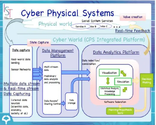
2.1.1.2Virtualization and Cyber physical systems
The virtualization of the factories of the future can be achieved using cyber-physical systems, that are composed by a physical entity embedded with a cyber entity(Wen & Guo, 2016). The cyber part contains a virtualization of the physical part so that it can replicate virtually any behaviour of the physical machine. Being a virtual/physical system allows the system to easily access and store information in the cloud. CPS also contain wireless embed wireless devices (Bordel Sánchez, Alcarria, Sánchez de Rivera, & Sánchez-Picot, 2016), which allow the various machines to interact and communicate with each other and with the network. The concept of cyber-physical systems is illustrated in figure 2-1.
2.1.1.3Decentralization and real-time capability
Nowadays, most factories use centralized control systems to meet their demand and goals. The main problem is that, with current market demand, centralized systems are pushed to their limits, because of their abilities to deal with complex plans, and variable control and logistics systems (Schuhmacher & Hummel, 2016). Decentralized control systems can overcome these problems by distributing operations between the various nodes of the system. In the previous section the characteristics of the CPFs and, their capacity of exchange between them were presented. These characteristics allow for the creation of collaborative platforms where various CPPS groups can obtain holistic information about their tasks and thus learn and be trained on different tasks (Kreimeier, Morlock, Prinz, Krückhans and Bakir, 2014).
The ability to obtain holistic information on certain tasks allows CPPS to make decisions through production control without superordinate control systems (Gräßler, Pöhler and Pottebaum, 2016). Therefore, the various production systems can determine production sequences by themselves, which, combined with real-time data analysis, leads to efficient real-time performance.
2.2
Kernel
According to (Mauerer, 2008) the kernel can be considered an enhanced machine that, in the view of the application, abstracts the computer on a high level. Therefore it can be viewed as a resource manager as it takes care of the various programs that are running concurrently in the system.
According to (Justin Garrison, 2010) it is the lowest level of software in the computer and responsible for interfacing all the applications running, down to hardware. Kernel is also responsible for managing the memory where these applications are loaded. Without the existence of a kernel, or another layer that could perform its roles, the user would need to restart his system every time he wanted to run a different program (as used to happen in first computer systems(brokenthorn.com, 2009)).
To achieve its goals Kernel needs to create and manage processes, allocate memory and manage the physical hardware(The Linux Information Project, 2004).
2.2.1Processes
resources (Tobergte & Curtis, 2013). These resources may include memory position, internal kernel data, open files and threads that represent the objects of activity within the process.
In order to store all this information, exists a large structure within the kernel called
task_struct (M. Tim Jones, 2008), that also contains memory pointers to relevant files and program dependencies. Whenever a program is created memory is allocated to create an instance of the task_struct. Within this structure can also been found the current state of the program, the table 2-1 describes the possible states of a process, as seen in (Robert Love, 2005).
Table 2-1 – Kernel process states.
2.2.1.1Process hierarchy and device management
In kernel processes follow a hierarchy since they are born, the first process is init, and it is launched during the last part of the booting phase. Every process has a unique PID (process identification value) (The Linux Information Project, 2005) that is received when a process is born. This value is sequential, which means that the next process value will be one unit higher than the one that was launched before. Because init is the first one to be launched its PID is 1 and it is the parent of every processes that it calls. Due to this hierarchy and, to the pointers stored in the task_struct, it is possible to track the last called process into the first. This is an
Task Process Description
TASK_RUNNING The process can run. This state can either imply that the program is either running or on a run queue.
TASK_INTERRUPTIBLE The process can’t run. This state is applied when a process is waiting for a certain synchronous signal to unblock (change status to TASK_RUNNING)
TASK_UNINTERRUPTIBLE The process can’t run. This state is similar to TASK_INTERRUPTIBLE but can’t be interrupted by a signal (however asynchronous signal can be received). It is used in delicate processes like the ones that involve spinning the hard drive disk or spinning heads.
TASK_ZOMBIE The task has terminated but the process that called the task can still access it until decides that isn’t necessary. When that happens the process descriptor is deallocated.
important characteristic, because it provides a very efficient way to locate parents through their children and vice-versa.
2.2.2Device and drivers management
Kernel is in charge of the device management, that can be achieved with the use of device drivers. As stated in (Rubini & Corbet, 2005) drivers can be considered software modules that make a particular piece of hardware respond to a well-defined internal programming interface. This means that a driver needs to accept requests from the software related to the device it controls, accept requests from the kernel and ensure that the kernel’s requests are executed with success. The requests are made through interrupt service routines and parsed using I/O protocols.
To organize this information kernel uses a process called udev. This process manages all the drivers and is in charge of supplying a dynamic device directory (dev), with the nodes of the devices that are currently connected to the system (Unnikrishnan A, 2009). Whenever a device is added or removed to the system an udev event is triggered and parsed according to
its rules files. If that event represents a connected device a directory is added into the dev directory (at each directory corresponds a different device), when the device is updated/changed, the information within this folder changes too. Finally if the device is removed, the folder is also removed.
2.3
FIWARE, the European project
FIWARE is a project that looks for the creations of a core platform on the context of the Future Internet Private Public Partnerships (FI-PPP), that is part of FP7(Seventh Framework Programme) of the European Commission (Tuominen, 2013). The programme’s final goal is to develop future internet technology which can be used in smart infrastructures and that will contribute for the technological competitiveness and growth of Europe.
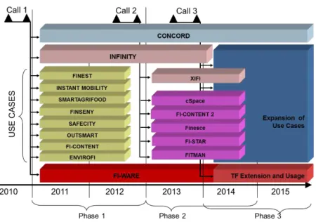
To fulfil its objectives, FI-PPP was divided in three phases that took place between 2011 and 2016 (“Future Internet Public and Private Parceries,” 2012). The first phase focused on the development of the project architecture, technology foundation and creation of specific enablers. Phase two concerned on the creation of infrastructure to operate an European network of FIWARE nodes. Phase three focused on probing the vitality of the project and expansion of the use cases. The development structure of FI-PPP can be seen in figure 2-3, it is also possible to verify the existence of important open source development tools, such as fiware (FI-CONTENT).
Figure 2-3: FI-PPP architecture(“CORDISArchive : European Commission : CORDIS : FP7 : ICT : Net
Innovation : FI-PPP Call 3,” 2013).
2.3.1FIWARE enablers
FIWARE offers many open-source technological resources and is based on elements that are called Generic Enablers (GE). The Enablers offer reusable and shared modules, which include protocols and interfaces for operation and communication, that are able to cover several usage areas among different sectors(Pablo Fernández , José Miguel Santana , Sebastián Ortega & José Pablo Suárez , Conrado Domínguez, 2016).
Although the activators can be applied in several different cases, a single service can not be applied in several areas. This means that there are specific facilitators for a specific area of focus that allows you to divide the modules into technical chapters. According to (Trindade et al., 2016) there are seven different chapters:
1. Cloud hosting
As one of FI-PPP's objectives was to improve the competitiveness of the European market, it has become important to provide a service to help start-up companies and even small businesses. Providing resources for this area means the improvement of a service that these types of companies were already paying according to their data storage needs. The services provided to the European cloud are business-to-business variables, when a business expands or increases the storage of data needs, it just needs to request more resources / data space. When choosing this type of service, a low initial investment is granted. To support the European cloud services, the specific FIWARE facilitators have been created, according to this chapter.
2. Data context/management
The rising of industry 4.0 leads to the emergence of smart factories and other business branches that produce a big amount of data. The analysis of this large quantity of information, whether it is structured or unstructured, demands specialized programs or applications. This FIWARE chapter looks forwards to develop Generic Enablers that provide an easier and faster way to create or integrate data analysis algorithms.
3. Internet of things
As several interoperable services appear it is important to integrate different systems. Considering that the architecture/programming language used among the various systems can be different, there must exist a system component/service that provides the knowledge translation among the systems. This chapter focus on obtaining information and making it available and accessible so that services can profit from the data collected.
4. Applications, Services and Data Delivery
5. Security
However the future industry promotes the interoperability between services and systems, it is inevitable that each device/system develops its own individuality. This way it is normal that each service has data transfer and security protocols that grant data integrity. This chapter deals with the enablers that create security features within protocols, allowing communication between different devices.
6. Interface with Networks and Devices(I2ND) Architecture
The I2ND is related to the creation of Generic Enablers that aim to execute a network infrastructure, whose model is standardized. The facilitators in this chapter need to be able to handle very sophisticated operators' terminals, proxies, and infrastructure. The successful management of these components ensures that the I2ND network can be accessed by other potential suppliers.
7. Advanced Web-based User Interface
It is important to provide the final user not only with service functionality but also with an environment that improves the user experience. This is achieved by adding user-friendly layouts, inputs and interaction capabilities, which include 3D graphics and systems virtualization. It is also granted compatibility with traditional web services and the opportunity to use more advanced features.
2.4
System Awareness and Data Harmonization
2.4.1Context models
There are many ways to establish the rules that will define the system´s classification methods, the simplest way is to use key-value definitions. Key values are always composed at least by a pair of two words (Bettini et al., 2010) as one is the attribute key and the other the meaning key. Traditionally, when using key-values definitions, the information will appear in the format <key,value> (Zhao & He, 2009). For example, the word “animal” can have associated an action and the word “bear” can have associated a value. In this kind of services the pair values are stored in tables within the system’s memory. A similar approach can be done using markup models, that instead of storing the correspondent pair of keys in tables, tag all the data and store them according to a defined hierarchy(Indulska, Robinson, Rakotonirainy, & Henricksen, 2003). In this case, the hierarchical data structures consist of mark-up tags, with attribute value (Patnaik, 2013).
Another possible solution can be achieved using logic based models as seen in (Strang & Linnhoff-Popien, 2004). These models have the context defined through several facts, statements and rules that, in the presence of the required conditions trigger the system´s response. For example, having the input “a” in the context “x” trigger the response “z”.
A more versatile solution is the use of ontology based models that involve knowledge representation languages. Ontologies provide a description about the target world, retrieving its concept´s through classes, members through instances and roles and needed information through relationships (Ian Horrocks, 2006). According to (Wang, Gu, Zhang, & Pung, 2004) ontologies provide advantages when considering knowledge sharing, logic inference and knowledge reuse:
1. Knowledge sharing
Using ontologies means that system entities such as agents and services have a common set of context, when interacting with each other. This also implies that it is easier for someone that has not high knowledge on a specific system, to make some modifications, since he has only to change the parameters within the ontologies.
2. Logic inference
Based on the information under the ontology a context-aware system can deduce high-level context from low-level context.
3. Knowledge reuse
2.4.2Context frameworks
When creating a model that has context involved it is necessary to make sure that the system levels process that information according to their designed function. As seen in (Stewart & Narasimhan, 2007)it is necessary not only to define the context, but also use levels/layers that take care of gathering storing and sharing it. The information gathering is usually made by sensors who need to have rules about when is necessary to retrieve the necessary information. For example a sensor used in a system that has as objective to collect the solar light intensity, does not need to collect the light values at night even if there is some moonlight. It is also necessary to ensure a mechanism that tolerates delays in a context sharing situation. Storing context is important when referring to a system that needs some added value, besides the real time information, as defended by (Salber & Abowd, 1998). Sometimes the system may need to predict the future cases/reactions and, that decision can be based on older information. The context use defines the situations that are necessary for the system to enable a behaviour or action and to decide whose methods were already discussed in the previous section.
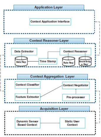
As seen in(Miguel & Miranda, 2014) the most common context architectures are hierarchical, with the possibility of having centralized elements. Having a hierarchical architecture allows to consume less processor and memory resources, however it also leads to a system failure if an element fails. The figure 2-4 illustrates a hierarchical presented in(Mamo & Ejigu, 2014):
In this architecture Information is obtained through the acquisition layer. The static user context module collects user information and, the dynamic sensor based context collects the information from sensors. Context aggregation layer processes the raw information from the acquisition layer and organizes it so that the context reasoner layer can easily process the obtained information. The information passes through a pre-processor that binds data from the two modules on the previous layer. Context negotiator determines the validity of retained data and sends it to the feature extractor, that determines the most important information within a block of data. That information is sent to the context classifier block, that combines the information’s attributes, creating new context classes or supporting existing ones. The information is then sent to the context reasoning layer where the information is processed based on defined rules and past experiences. Finally, on the application layer the system interacts with user based on the processed information.
2.4.3Situation awareness
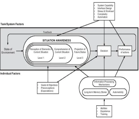
In the previous chapters the mechanisms related to the system awareness were discussed. The levels that a system needs to have, to grant action and decision making, were explained. However, to address the presented hypothesis, it is also necessary to understand what is the logic used to explain how an individual can achieve awareness, from the information at its range. Below will be explained several different mental models, which provide explanations about how individuals achieve awareness, by analysing the available information (Morrison, 2012). The models to be explained are the three level model, the perceptual cycle model and the activity theory model(Panteli & Kirschen, 2015).
Figure 2-5: The three level module for situation awareness (Panteli & Kirschen, 2015)
Regarding the perceptual cycle model, (Plant, Stanton, & Harvey, 2013) and (Giacobe, 2013) explain that it is based in the interaction of the individual with the world. To use this model there are three important concepts, the environment information, the schema of present environment and perceptual exploration. The environment information is related to the potential information extracted from the system’s world. The perceptual exploration concerns the information that can be achieved from exploration (like for example the perception that a surface is wrinkled from touching it) and provides it to perceptual information. The schema of present environment is the big picture model, that is created from the previous images of the world. In this model all the three levels coexist and modify each other, perceptual exploration provides environment information with real time data that it uses to create a world image. By comparing the current world image with the schema of present environment it is possible to make decisions. Whenever the current schema is outdated or does not allow to make the best decision it is rewritten according to the current world picture. The information contained in the schema provides standard decisions or actions that allow perceptual exploration to retrieve the most accurate data.
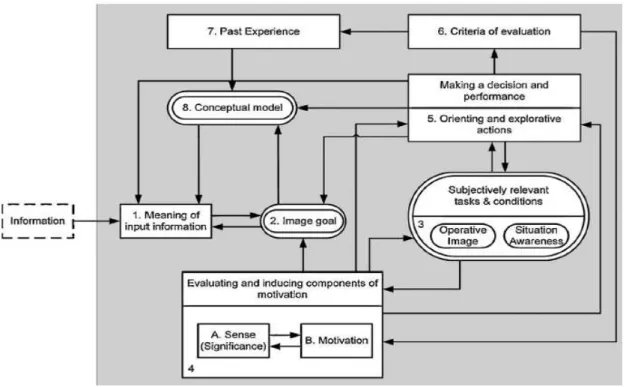
Figure 2-6: Activity theory model diagram (Panteli & Kirschen, 2015)
The new information arrives on block 1 and is interpreted according to the model of the world (block 8),the purpose of the information (block 2) and orientation according to the to the objective of the information (block5). The interpretation of this information goes to block 2. According to this interpretation the individual can decide what are the relevant tasks to process the information (block 4) and their relevance to the world (block 5) based on a criteria evaluation (block 6). The result of the evaluation will direct person’s engagement with the world(block5) and new criteria will be developed (block 6). The interaction with the world will be stored as experience (block 7) and inform representation of the world (block 8). This process repeats for new information, at each interaction the conceptual model will be based on each time more knowledge which leads to a more efficient decision making.
2.4.4Data harmonization levels
As it was already mentioned, sometimes within a system formed by a group of sub-systems exists heterogeneous information. This may happen because not all the sub-systems have the same architecture or were not built in the same language and do not have the ability to exchange data. It is possible to know about data specifications and properties using its metadata. Metadata is simply information about the data itself and has several types, as shown in (Rebecca Guenther, 2003). Descriptive metadata contains information about the type and author, that allow a system to realise if a set of data is compatible with it and therefore verify if there is immediate interoperability.
processes. Usually this case is more a policy problem than a data problem, since the data can still be read and used. Legal level incompatibilities happen when merging two datasets while one of them has restricted access from its creator. The syntax level is related to whether the structure of information data can be successfully merged. When two different data sources use different data models to store information that looks alike, the merge of the two datasets cannot be done without a prior normalization. Technical level deals with problems related to the means of transport of information. For example, merging information received from bluethoot with text typed, can imply some difficulties because they are different data types. Semantic level takes care of issues related to the ambiguity of identifiers. When for example considering two different datasets that have a client’s name list, one can have a field with the complete name and the other two fields, one with the first name and the other with the last. Finally, query level is of major importance when merging information that is split into multiple data files. For example, when merging client’s information to create a complete file, information like email can be in one file and cell phone number in another, in this case it is necessary to perform several small queries to gather the information
2.4.5Data harmonization framework
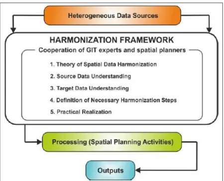
The data coming from different sources must be harmonized to achieve a common data standard which can be processed by the system. Although exist several methods, usually the process is common to several data types, as it is illustrate in figure 2-7. The process starts with establishing an inventory of the current data requirements, definition of the data collected(1), analysis of the information requirements and data elements(2,3,4) and reconciliation of the data (5) (United Nacions Economic Comission for Europe, 2017). When processing data, each dataset is considered to be formed by several series of statements that are serialized according to a particular syntax(Colpaert et al., 2014). Some syntaxes, like TSV, represent information using tables, where each cell in each row contains the statements. Syntaxes like XML and JSON represent information hierarchically (within a tree structure). Because the syntaxes are different, some of the normalization steps will have to be specialized to a certain syntax.
Figure 2-7: Data harmonization process(Wc & Corve, 2015)
The three first steps within the framework are common to most normalization processes, the understanding of source data is done using metadata in-formation, as referred before. The fourth step will depend on how the syntax stores the information and according to that will be created personalized harmonization steps.
2.5
State of the art conclusions
After explaining the theories that allow answering the question of research, it is important to review some of the presented concepts and compare approaches, considering the opinion of the Author on the work to be developed. The first section was related to the factories of the future and explained how the IoT concepts influence industry 4.0. During the explanation of the characteristics of FoF the concept of interoperability was introduced and, the several approaches that can be carried out to exchange data from different systems, were explained from a high level point of view. From the explained approaches (CORBA, mediated approach, agent approach and webservers), the one that best fits this work is the web server solution. Comparing the four approaches, the web server is the easiest way to exchange information, considering that there are several enablers that work in this domain, as seen in the Fiware section (Internet and Cloud Application Chapters). It can also be considered an enabler of the internet chapter based on cloud storage,to transfer information stored over the internet.
logic can be used by the vf-APPS, when interacting with sensor devices. In this case, the system’s applications would request the information, making it understandable to the device, through a software module. The recovered sensor information could be stored using webservers and accessed through Fiware enablers.
In the System Awareness and Data Harmonization section the ways how a system can be aware of the elements that surround him and, how to use that information to react, were explained. The models that allow to describe a system and create context were also explained. Considering a simple framework, key value pars can be used, considering that there is not necessary a hierarchy between the several rules to be applied. The same can not be done with complex frameworks that demand a high level of context description and definition. From the provided models, the Autor considers Ontologies to be the most complete, however, may exist enablers that combine the models’ strengths and that allow to reason context.
Several mental model theories were also explained, in order to find one that could be used to create a context framework compliant with the way how individuals achieve awareness. The activity theory model defends that the information gathering and analysis depend on the nature of the task and, on the goals of the individual. This logic is not fit to be used in a system that needs to be able to impartially analyse sensor data. The perceptual cycle model is based in the interaction of the individual with the world. Considering this model’s application cases, it would be better used in a machine learning system, because it would provide such a system with tools to grow smarter. Finally, the three level model, uses several levels to achieve situational awareness (perception, comprehension, projection). This model can infer about the analysed data, because it effectively defines the functions of each level in detail. Considering the models that were presented, this is the one that describes with higher detail the necessary steps to achieve awareness. By relying on this model, it is possible to create an analogy for a framework that uses it to obtain context evaluations, based on collected sensor data.
3
System Architecture
This section aims to explain the technologies in which the framework is based and also present its architecture. The first chapter introduces an agriculture practical scenario, as the problem to be addressed. To Solve this problem, it is proposed to use a context based framework that is able to interpreter sensor data from crop sensors, based on provided rules. The framework’s architecture takes in consideration concepts of the three level mental model explained in the previous chapter. The framework section shows in detail each part of the framework’s structure, starting the presentation from a very high level and then explaining each module in detail. Besides an architecture it is necessary to identify a set of specific tools that allow to build it. Orion and Docker sections present in detail these technologies and explains how they can be used to create the framework. When dealing with sensor data, can occur harmonization problems, if the sensor’s architecture it is incompatible with the framework’s sensor model, this thematic is addressed in the harmonization chapter. Sensor data mismatches section, explains the integration problems that a framework may find, when dealing with different sensor models. Harmonization guidelines section present solutions to integrate different sensor types with the framework, taking in consideration how the information is retrieved. The last part of this chapter has as objective to relate the developed framework’s needs with vf-OS, resulting in the final system architecture.
3.1
Scenario
Modern agriculture uses sensors to grant high product quality that rewards farmers with higher profits. The usage of sensors can also be applied in several parts of the product chain increasing the product quality. This sensor technology that makes farms more intelligent, with real-time data gathering, processing and analysis is called ‘smart farming’ (Kamilaris et al., 2016). The chosen scenario deals with a modern fruit product chain that deals with the product from harvest to client delivery.
After fruit is harvested by the farmer, it is separated (manually or mechanically) and submitted to quality control to confirm that the desired standards have been achieved. The several strains of fruits are split according to the desired characteristics and made available to the client. From the moment that the product has been made available clients can decide which products to choose according to his own needs. To perform this, exists a buyer’s application that allows not only to view the farmers registered in the platform but also to choose the products, based on features such as fruit strains and measurements. When client purchases a product, farmer receives a request and chooses weather to accept it or not, if he accepts it the product is shipped. The transportation is also monitored with sensors, informing the client of the conditions felt by the fruit. The figure 3-1 and table 3-1 describe this process:
Figure 3-1: Global Scenario
Table 3-1 – Scenario Steps
Steps Explanation
1 Fruit harvest, controlled by IoT Devices
2 Fruit selection, separation (manually or automatically) 3 Fruit boxing
During the whole process can be used several technologies according to the necessary processes, such as harvest, transport, etc. Regardless the process used, due to the presence of sensors and software that use the recovered data, it is possible to be aware of the product’s situation in real time. That information is recorded and delivered to the final client at the end of the product chain. The large amount of control during the process can be used not only to control the product´s quality but also his valor.
To fully achieve this scenario there must exist several functionalities to satisfy the different needs (such as quality monitoring, packing, monitoring during transportation, product request among others). In order to achieve a solution that can grant high product quality, based on information gathered by the sensors within the crop (red selection within figure 3-1) can be used a context based framework.
3.2
Framework
Figure 3-2: Framework High level architecture
The Acquisition Layer is responsible for obtaining sensor information. Its functions include knowing when new information has been inserted and removing information regarding the actual sensor data. The information that is processed by this layer comes from the sensors.
Sensor Data Harmonization Layer, is responsible for retrieving the sensor data from the previous layer and deploying it to the Sensor Repository. To achieve this, there must be a pre-processing where the different types of information within the sensor message are identified. This information is subsequently analyzed and subjected to harmonization. The harmonization process, refers to the different cases that will be presented in the data harmonization section. Once the information is harmonized and consistent with the structure data format, it is deployed in the repository and is available for higher layers.
The Aggregation / Reasoning Context layer finds the rules responsible for verifying whether the context that "judges" sensor data is verified or not. To achieve this, the layer identifies the rules that act on a particular sensor and, from them, obtains the context that encompasses the rules. This context and rules are those available in the rule repository. The rules are checked one by one, if they match, the context is checked successfully if the context is not failed. Information about whether a context is checked is available for the Application Layer.
3.2.1Acquisition Layer
Acquisition Layer retrieves the information that is received from the sensors, processes that information and sends it to Data Harmonization Layer. For that reason, it is necessary to define how the event of receiving data will be handled. In (Perera, Member, Zaslavsky, & Christen, 2013) events are considered to be occurrences that trigger conditions in a target area, they can be one of two types:
• Discrete Event: An event that occurs at a certain time (t) and at that certain time plus a time period (t+p). Because in these kinds of events exists a time period (p) between the first and second occurrences there are considered to be two different event instances.
• Continuous Event: An even that occurs at a certain time, where t and t+p cannot be considered a valid measured interval and consequently is only considered one event.
Figure 3-3: Acquisition layer behaviour
In this architecture, the system expects a new data deployment and checks, in (large) intervals, whether new sensor information has been implanted. When new information arrives, its processing begins. The incoming information can belong to several sensor types, such as measuring sensors and readings from laser counting sensors. This information can even be mixed and, for this reason, this layer must process the information, separating all information into individual sensor data. This information is then sent to the Sensor Data harmonization layer and the process of waiting for new sensor restarts.
3.2.2Data harmonization Layer
Figure 3-4: Key par values example from (Symposium et al., 2015)
To define which set of items provide a minimalist set of interoperable features, it is necessary to first define what the application needs to read the sensors. In addition to the data readings collected by the sensor applications, there is also a need to know parameters such as the sensor identifier and the capture date. On the other hand, the applications that analyze the information collected need to know parameters such as type and unit.
When a request is made to a sensor, the information collected does not contain just the required pair of keys. When considering the wireless sensor based on XMPP should be considered a much greater response. XMPP (Extensible Messaging and Presence Protocol) is a protocol used for real-time information exchange on the internet. By applying this protocol to wireless sensors, it is possible to exchange recovered data between the user and a group of sensors as seen in (Hornsby, Belimpasakis, & Defee, 2009). An adapted example of (Waher, 2016) is shown in Figure 3-5.
<message from='[email protected]'
to='[email protected]/amr'>
<fields xmlns='urn:xmpp:iot:sensordata' seqnr='1' done='true'>
<node nodeId='Device01'>
<timestamp value='2013-03-07T16:24:30'>
<numeric name='Temperature' momentary='false' automaticReadout='true'
value='30’ unit='°C'/>
</timestamp>
</node>
</fields> </message>
Figure 3-5: XMPP sensor response
In figure 3-9, it is possible to observe fields that represent sensor information. The from and to fields refer to the device that is sending the message and the client who is receiving it. The node field tells what is the sensors identification within its owning node. Depending on the network size is possible that exist two sensors with the same id, which is not necessary a problem since that on the message request is specified the required node. The timestamp value refers to the time when the readings were retrieved, and between its brackets rest the readings and some additional information. Although this fields are specially important to VHarvest it is necessary to reference them, since they exist on the data sent from the Acquisition Layer.
Figure 3-6: Data Harmonization layer behaviour
The Layer’s work starts with the Raw Sensor Data delivered by the previous layer. This information passes through a preprocessor so that key information can be retrieved. As seen before, within the message of a sensor, there is much information that is not. The function of the Data Pre-Processor module is to eliminate the excess information. Considering Figure 3-9, its role is to obtain, in a first phase, the content between the timestamp supports. In a second phase, the values contained in the brackets are analyzed and stored in memory.
The retrieved information can then be stored in Data Repository, if it is already in a format compatible with the framework’s data instance or else pass through an harmonization process. The frameworks representation of a sensor consists in a minimalist set of information, with the purpose of easing the integration process. It consists of a table called SensorReading that only contains an ID and value, this small amount of information for a representation solves by itself some of the possible information exchange mismatches. The harmonization consists in a series of functions, each one designed to solve a particular mismatch problem. According to the number of different mismatches, it can occur that a sensor passes through several harmonization functions.
3.2.3Context Aggregation/Reasoning Layer
aggregation and context verification work it is first necessary to understand what is the framework’s representation of context and rules and how they interact with sensor’s values representations. The 3-7 depictures this relation:
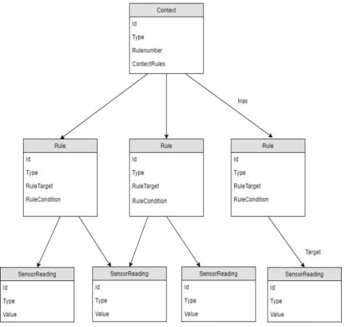
Figure 3-7: Context, Rules and Readings relation
The context’s representation contains an identificatory field with its name and also Type, Rulenumber and ContextRules fields. The type field identifies the context element and, allows the system to understand if it is a context element or a rule element. It is necessary to have the type attribute because, it may ease further processing, when selecting the context and rules to reason. Rulenumber identifies the number of rules that a context needs to be verified. Imagine as an example, the measuring of a context for whose is necessary to have two different rules, its verification is far different from checking a context that only has one rule. ContextRules contains a list of all the rules existing in the system, under a defined Context.
The Sensor’s representation is called SensorReading and has already been introduced in the previous section, it is a minimal representation, containing only an ID, Type and Value. The ID value identifies the Reading and is composed of the sensor name plus the reading number. As an example, the ID of a sensor called TemperatureSensor would be “TemperatureSensorxxx”, where xxx would be measure number (001,002,003, etc.). The type field contains the Sensor name, considering the previous example its value would be “TemperatureSensor”. The Value field contains the valued read by the sensors at a determined time moment.
As it is possible to verify by the previous image information is compartmentalized, this means that a context element only knows what are his rules, rules know their corresponding context and SensorReadings to target and, SensorReadings don’t know any of the other entities. The process of rules evaluation and context verification can be observed in figure 3-8.
Figure 3-8: Context Reasoning layer behaviour