Nuno Miguel de Brito Delgado
BSc in Computer Science
A System’s Approach to Cache
Hierarchy-Aware Decomposition of
Data-Parallel Computations
Dissertação para obtenção do Grau de Mestre em Engenharia Informática
Orientador: Prof. Doutor Hervé Miguel Cordeiro Paulino, Prof. Auxiliar, Universidade Nova
de Lisboa
Júri:
Presidente: Prof. Doutor António Maria Lobo César Alarcão Ravara
Arguentes: Prof. Doutor João Pedro Barreto
Vogais: Prof. Doutor Hervé Miguel Cordeiro Paulino
iii
A System’s Approach to Cache Hierarchy-Aware Decomposition of Data-Parallel Computations
Copyright © Nuno Miguel de Brito Delgado, Faculdade de Ciências e Tecnologia, Uni-versidade Nova de Lisboa
Agradecimentos
Em primeiro lugar, quero agradecer ao Prof. Hervé Paulino por toda a atenção disponibi-lizada e apoio prestado ao longo do período de desenvolvimento desta dissertação, não só a nível profissional como também pessoal.
Quero também agradecer ao Departamento de Informática da Faculdade de Ciências e Tecnologia da Universidade Nova de Lisboa, pelas excelentes condições de trabalho que me foram proporcionadas para o desenvolvimento deste trabalho, bem como por todas as oportunidades de envolvimento nas activades de investigação e apoio pedagógico do departamento, nas quais desenvolvi competências que me foram imensamente úteis ao longo do desenvolvimento desta dissertação.
Abstract
The architecture of nowadays’ processors is very complex, comprising several computa-tional cores and an intricate hierarchy of cache memories. The latter, in particular, differ considerably between the many processors currently available in the market, resulting in a wide variety of configurations. Application development is typically oblivious of this complexity and diversity, taking only into consideration the number of available execu-tion cores. This oblivion prevents such applicaexecu-tions from fully harnessing the computing power available in these architectures.
This problem has been recognized by the community, which has proposed languages and models to express and tune applications according to the underlying machine’s hier-archy. These, however, lack the desired abstraction level, forcing the programmer to have deep knowledge of computer architecture and parallel programming, in order to ensure performance portability across a wide range of architectures.
Realizing these limitations, the goal of this thesis is to delegate these hierarchy-aware optimizations to the runtime system. Accordingly, the programmer’s responsibilities are confined to the definition of procedures for decomposing an application’s domain, into an arbitrary number of partitions. With this, the programmer has only to reason about the application’s data representation and manipulation.
We prototyped our proposal on top of a Java parallel programming framework, and evaluated it from a performance perspective, against cache neglectful domain decom-positions. The results demonstrate that our optimizations deliver significant speedups against decomposition strategies based solely on the number of execution cores, without requiring the programmer to reason about the machine’s hardware. These facts allow us to conclude that it is possible to obtain performance gains by transferring hierarchy-aware optimizations concerns to the runtime system.
Resumo
Ao longo dos últimos anos, o aumento do poder computacional dos CPUs tem sido alcan-çado através do aumento do número de cores e não através do aumento da frequência de relógio. Esta tendência levou à ascensão dos modelos multicore a modelo arquitec-tural predominante nos computadores de hoje em dia. Estes CPUs têm o potencial de aumentar a velocidade de programas que possam tirar partido de computação paralela. Além dos seus múltiplos cores, estes apresentam hierarquias de cache complexas, com diferentes configurações e afinidades aos cores existentes, abrindo assim as portas para optimizações cientes destas hierarquias.
Simultaneamente, as frameworks de programação estão incrementalmente a passar de modelos sequenciais para modelos paralelos, de modo a explorar na totalidade o po-tencial adormecido destas arquitecturas. A incorporação de paralelismo é feita através exposição explícita deste ao programador, ou através de transformações implícitas de código que introduzem paralelismo automaticamente.
A introdução de paralelismo por si só, contudo, não garante que o hardware está a ser utilizado no seu máximo. O mapeamento adequado de uma aplicação para a hierarquia de cache subjacente é crucial para explorar ao máximo o poder computacional destas arquitecturas. Os ganhos de desempenho derivam essencialmente da exploração tanto da localidade temporal como da espacial, no acesso aos dados. Contudo, a gestão das memórias cache é completamente transparente na programação de nível utilizador. Esta responsabilidade recai tipicamente sobre a infraestructura de hardware, cuja função é apenas garantir que dados acedidos recentemente estão mais próximos da unidade de computação do que os restantes, dado que provavelmente serão acedidos novamente.
xii
Contents
1 Introduction 1
1.1 Motivation . . . 1
1.1.1 Motivational Example . . . 2
1.2 Problem . . . 4
1.3 Proposed Solution . . . 5
1.4 Contributions . . . 6
1.5 Document Organization . . . 6
2 State of the Art 7 2.1 Hierarchical Parallelism . . . 7
2.2 Hierarchical Programming Models . . . 10
2.2.1 Sequoia . . . 10
2.2.2 Hierarchically Tiled Arrays . . . 14
2.2.3 Hierarchical Place Trees . . . 17
2.2.4 Hierarchical SPMD . . . 20
2.2.5 Unified Parallel C . . . 22
2.2.6 Fractal Component Model . . . 23
2.3 Hierarchical Work Distribution . . . 25
2.4 Discussion . . . 26
3 Hierarchical Domain Decomposition 29 3.1 Data-size Driven Decomposition . . . 30
3.2 Scheduling . . . 35
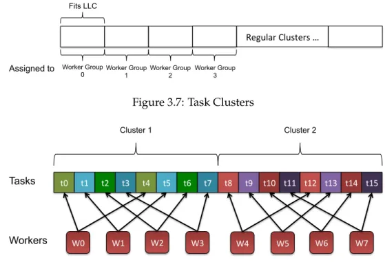
3.2.1 Contiguous Clustering (CC) . . . 37
3.2.2 Sibling Round-Robin (SRR) Clustering . . . 37
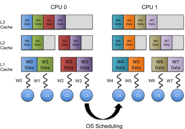
3.3 On the Affinity between Workers and Cores . . . 40
3.3.1 Lowest-Level-Shared-Cache Affinity Mapping . . . 41
xiv CONTENTS
4 Implementation in the Elina Framework 43
4.1 The Elina Framework . . . 43
4.1.1 Parallel Programming in Elina . . . 44
4.1.2 Runtime System . . . 45
4.1.3 Elina Initialization . . . 46
4.1.4 Elina Execution Workflow . . . 47
4.2 Vertical Decomposition in Elina . . . 48
4.2.1 New Adapter Types . . . 48
4.2.2 New Adapter Implementations . . . 53
4.2.3 Supporting Dynamic Memory Allocation . . . 54
4.2.4 Discussion . . . 55
5 Experimental Evaluation 57 5.1 Methodology . . . 57
5.2 Benchmarks . . . 58
5.3 Test Infrastructure . . . 59
5.4 Vertical vs Horizontal Decomposition . . . 59
5.4.1 Matmult, Transpose, Gaussian Blur . . . 61
5.4.2 Saxpy, Series . . . 71
5.4.3 Breakdown . . . 71
5.5 Discussion . . . 73
List of Figures
1.1 Matrix Transposal Iteration Pattern . . . 3
1.2 Matrix Transposal Iteration Pattern (revised) . . . 4
2.1 Memory Hierarchies examples, taken from [ACF93]. . . 8
2.2 Matmul::inner decomposition into subtasks, taken from [FHK+06]. . . 13
2.3 Pictorial view of an Hierarchically Tiled Array [BGH+06]. . . 15
2.4 HTA construction-(a). Mapping of tiles to processors-(b) [BGH+06]. . . 15
2.5 HTAs components access [BGH+06]. . . 16
2.6 A Hierarchical Place Tree example, taken from [YZGS10]. . . 18
2.7 Three different HPT abstractions a, b and c of the same machine. . . 18
2.8 PGAS Address Space Model [CDC+99]. . . 19
2.9 Team hierarchy example [KY12]. . . 20
2.10 Shared memory sorting algorithm using four threads [KY12]. . . 21
2.11 Fractal component types examples, taken from [BBC+06]. . . 24
2.12 3D renderer component model, taken from [BBC+06]. . . 24
3.1 Invalid (a) and valid (b) Stencil Partitions . . . 31
3.2 Best case scenario of a partition’s line mapping onto cache lines . . . 34
3.3 Worst case scenario of a partition’s line mapping onto cache lines . . . 34
3.4 Block decomposition for the matrix multiplication problem . . . 36
3.5 Contiguous Clustering: Worker-Tasks Mapping . . . 37
3.6 Example Cache Hierarchy . . . 38
3.7 Task Clusters . . . 39
3.8 Sibling Round-Robin Clustering: Worker-Tasks Mapping . . . 39
3.9 Operative System rescheduling a worker . . . 41
3.10 Lowest Shared Cache Affinity Mapping . . . 42
4.1 The SOMD Execution Model . . . 45
xvi LIST OF FIGURES
4.3 Elina Initialization Workflow . . . 47
4.4 Elina Execution Workflow . . . 47
5.1 Horizontal vs Vertical decomposition: workingset granularity . . . 60
5.2 S1 Speedups: MatMult (Contiguous Clustering) . . . 63
5.3 S1 Speedups: MatMult (SRR Clustering) . . . 63
5.4 S1 Speedups: MatTrans (Contiguous Clustering) . . . 63
5.5 S1 Speedups: MatTrans (SRR Clustering) . . . 64
5.6 S1 Speedups: GaussianBlur (Contiguous Clustering) . . . 64
5.7 S1 Speedups: GaussianBlur (SRR Clustering) . . . 64
5.8 S2 Speedups: MatMult (Contiguous Clustering) . . . 65
5.9 S2 Speedups: MatMult (SRR Clustering) . . . 65
5.10 S2 Speedups: MatTrans (Contiguous Clustering) . . . 65
5.11 S2 Speedups: MatTrans (SRR Clustering) . . . 66
5.12 S2 Speedups: GaussianBlur (Contiguous Clustering) . . . 66
5.13 S2 Speedups: GaussianBlur (SRR Clustering) . . . 66
5.14 S3 Speedups: MatMult (Contiguous Clustering) . . . 67
5.15 S3 Speedups: MatMult (SRR Clustering) . . . 67
5.16 S3 Speedups: MatTrans (Contiguous Clustering) . . . 67
5.17 S3 Speedups: MatTrans (SRR Clustering) . . . 68
5.18 S3 Speedups: GaussianBlur (Contiguous Clustering) . . . 68
5.19 S3 Speedups: GaussianBlur (SRR Clustering) . . . 68
5.20 S1 Speedups: Horizontal and Vertical (Contiguous Clustering) vs Sequential 69 5.21 S1 Speedups: Horizontal and Vertical (SRR Clustering) vs Sequential . . . 69
5.22 S2 Speedups: Horizontal and Vertical (Contiguous Clustering) vs Sequential 70 5.23 S2 Speedups: Horizontal and Vertical (SRR Clustering) vs Sequential . . . 70
5.24 S3 Speedups: Horizontal and Vertical (Contiguous Clustering) vs Sequential 70 5.25 S3 Speedups: Horizontal and Vertical (SRR Clustering) vs Sequential . . . 71
5.26 SAXPY and Series S1 best configuration speedups . . . 72
5.27 SAXPY and Series S2 best configuration speedups . . . 72
5.28 SAXPY and Series S3 best configuration speedups . . . 73
5.29 S1 Breakdown: MatMult N=2000 . . . 73
5.30 S1 Breakdown: MatTrans N=10000 . . . 74
5.31 S3 Breakdown: MatMult N=4000 . . . 74
Listings
1 Matrix Transposal Algorithm . . . 2
2 matmul::inner task, taken from [FHK+06] . . . 12
3 matmul::leaf task, taken from [FHK+06] . . . 12
4 Matrix multiplication task configuration for a Cluster, taken from [FHK+06]. 14 5 Recursive matrix multiplication that exploits cache locality [BGH+06]. . . 16
6 DivideTeam method, taken from [KY12]. . . 21
7 Shared memory sort implementation with thread teams, taken from [KY12]. 22 8 TheDistributioninterface . . . 32
9 Matrix Multiplication Example . . . 45
10 TheHierarchyReadDriverinterface . . . 48
11 TheHierarchyLevelclass . . . 49
12 8-core Machine Hierarchy Representation . . . 50
13 64-core Machine Hierarchy Representation . . . 51
14 TheWSEstimationDriverinterface . . . 51
15 TheAffinityMappingDriverinterface . . . 52
16 TheDomainDecompositionDriverinterface . . . 53
17 TheSchedulingDriverinterface . . . 54
1
Introduction
1.1
Motivation
Over the last years, the increase of CPU computational power has been sought through horizontal scaling of processing cores rather than the increase of clock frequency. This trend led to the rising of the multicore model as the de facto architectural model for today’s computers. These CPUs have the potential to increase the overall speed of pro-grams amenable to parallel computing. In addition to their multiple cores, these fea-ture complex cache hierarchies with different configurations and affinities to the existing cores, opening the doors for hierarchy-aware optimizations.
Simultaneously, programming frameworks are incrementally moving from sequen-tial to parallel ones, to fully exploit the dormant potensequen-tial of these architectures. The incorporation of parallelism is carried forward either by explicitly exposing this paral-lelism to the programmer, or by performing implicit code transformations that automat-ically introduce parallelism.
The introduction of parallelism per se, however, does not guarantee that the hard-ware is being used to its fullest. Adequately mapping an application onto the underlying cache hierarchy is crucial to fully harness the computational power of these architectures. These performance gains derive essentially from the exploitation of both temporal and spatial cache locality in the access to data. However, the cache memory management is completely transparent to user-level programming. This responsibility typically falls upon the hardware infrastructure, whose function is only to guarantee that data accessed recently is closer to the computing unit than the remainder, since it will likely be accessed again.
1. INTRODUCTION 1.1. Motivation the efficient programming of applications for multicore processors. Our work scope will focus on optimizations driven by the cache hierarchy of the underlying hardware.
1.1.1 Motivational Example
Although we have presented an overview of the challenges and potential performance gains of hierarchical decomposition, an example can better illustrate the rationale behind these gains and how large these can theoretically be.
Let’s consider a well-known linear algebra operation, the transposal of a matrix. The mathematical properties of the operation are not the focus in the context of this thesis, so we will rely solely on a Java implementation of the algorithm that performs the operation, presented in Listing 1, as the base for our discussion.
1 v o i d t r a n s p o s e (i n t[][] A , i n t[][] T ) {
2 f o r(i n t i =0; i < A . l e n g t h ; i ++)
3 f o r(i n t j =0; j < A [0]. l e n g t h ; j ++)
4 T [ i ][ j ] = A [ j ][ i ];
5 }
Listing 1: Matrix Transposal Algorithm
It is worth noting that the arguments and reasoning afterwards presented assume that the lines of bi-dimensional arrays are stored in row-major order in memory. Row-major order describes methods for storing n-dimensional arrays in memory which store rows contiguously in memory, in contrast with column-major order, which stores columns (for bi-dimensional arrays) contiguously in memory rather than rows. To illustrate this con-cept, consider the following matrix:
M =
"
1 2 3 4 5 6
#
IfM was stored in a row-major order, the elements ofM would be laid out contigu-ously in memory as{1,2,3,4,5,6}. On the other hand, ifMwas stored in a column-major order, its elements would be laid out as{1,4,2,5,3,6}. Row-major order is prevalent in most programming languages, including Java.
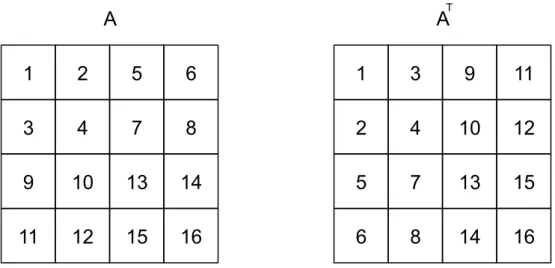
We can observe that when the algorithm iterates matrixAacross its lines,Tis iterated across its columns. IfAandTare square matrices with sideN = 4, we will have the iter-ation pattern illustrated in Figure 1.1. The value in each block of each matrix represents its order number in the sequence of accesses to the matrix by the algorithm.
1. INTRODUCTION 1.1. Motivation
1
2
3
5
6
7
9
10
11
4
8
12
13
14
15
16
A
1
5
9
2
6
10
3
7
11
13
14
15
4
8
12
16
A
TFigure 1.1: Matrix Transposal Iteration Pattern
line are also brought into the cache, but sinceTis iterated across its columns, ifTis large enough, these elements will eventually be removed from the cache to make space for the elements accessed afterwards by the algorithm. This results in a "waste" of cache hits that could have resulted from sequential accesses across the lines ofT.
Having each computation well mapped onto the underlying memory hierarchy can provide applications with significant performance gains. If one divides computations into tasks that execute with a reduced input workload fitting the smallest cache level, one can expect to fully exploit both temporal and spatial cache locality during the execution of each task.
Consider that all blocks of the matrices A andT have the same size in bytes. Now imagine a hypothetical architecture with a cache line size of 2 blocks, and a cache size of 8 blocks. If we divide the original transposal operation into 4 transposal operations that operate over different quadrants of the matrices, and a single CPU executes these opera-tions starting from the top left quadrant ofAand ending with the lower right quadrant, we will have the iteration pattern depicted in Figure 1.2.
1. INTRODUCTION 1.2. Problem
1
2
5
3
4
7
9
10
13
6
8
14
11
12
15
16
A
1
3
9
2
4
10
5
7
13
11
12
15
6
8
14
16
A
TFigure 1.2: Matrix Transposal Iteration Pattern (revised)
1.2
Problem
When performing hierarchy-specific optimizations, there are several aspects that one may take into account and tackle:
• Cache sizes
• Cache layer sharing (dedicated or shared)
• Cache alignment
• Target cache level
• Sibling core couples
• Inclusive or exclusive data storing policy across layers
The greatest challenges in this context are how to perform these optimizations with the minimal intervention from the programmer, who should not be concerned with complex hierarchy details when developing his applications, and how to program applications in a way they can be mapped onto different hierarchy configurations using the same source code.
Several state-of-the-art approaches like Sequoia [FHK+06], Hierarchical Place Trees [YZGS10], Hierarchically Tiled Arrays [BGH+06] and [TBA13] provide machine abstrac-tions for the programmer to abstractly represent the hierarchy of the target machine. Us-ing these abstractions, the programmer can choose where each computation takes place and define the size of its input workload.
1. INTRODUCTION 1.3. Proposed Solution In this thesis we propose a system-based approach to hierarchical parallelism where these optimization parameters are inferred and automatically tuned by the runtime sys-tem/compiler instead of being manually set by the programmer.
1.3
Proposed Solution
The popularity of Google’s MapReduce parallel programming framework [DG08] led to the generalization of the MapReduce designation, which nowadays is more associated with a programming paradigm, than to Google’s original programming model. This programming paradigm is characterized by a workflow of three main stages: Split de-composes the given input dataset into a system defined number of partitions,Mapapplies a given computation, in parallel, to each of such partitions, generating a set of results that may then be reduced by the last stage,Reduce, that produces the computation’s final result.
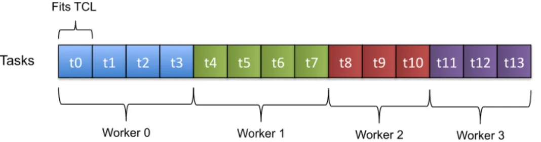
In this work, we are particularly interested in theSplitstage. Common domain de-compositions split the input dataset into a predetermined number of partitions. Within a single computing node, this number is usually bound to the number of worker threads assigned to the operation (assume N to be the arity of such set). Ergo, the domain is partitioned as evenly as possible between theseN workers, spawning that many tasks.
This approach is cache hierarchy-neglectful and hence, in many cases, does not har-vest the benefits provided by the (consistently growing amount of) cache hardware avail-able in current computers, from laptops to high-end server nodes. Our proposal over-comes this limitation by applying a vertical, cache-aware, decomposition strategy to the
Split stage that takes in account cache sizes and CPU cores affinities. As a result, the number of partitions (that we generalize into working sets) will no longer be bound to the number of workers available to perform the computation, but instead be a function of the target machine’s cache hierarchy. The Splitoperation is, itself, divided into two stages: the first performs the aforementioned vertical domain decomposition, while the second generates the tasks that will actually be executed by the workers assigned to the computation.
1. INTRODUCTION 1.4. Contributions The statement of this thesis is: it is possible to obtain performance gains in the exe-cution of data-parallel computations by systematically decomposing the computation’s domain, in such a way that it leverages the benefits of the cache hardware, without re-quiring additional attention from the programmer’s part.
1.4
Contributions
Our concrete contributions with this dissertation are the following:
• A collection of theoretical concepts and problems involved in hierarchy-based do-main decomposition. These concepts are complemented with algorithms and heuris-tics that attempt to solve these problems;
• A framework that allows programmers to have their applications automatically and efficiently mapped onto a target machine’s memory hierarchy, with minimal intervention from the former;
• An evaluation that reveals the speedup of a vertical domain decomposition ap-proach against a horizontal, core-based domain decomposition apap-proach.
1.5
Document Organization
2
State of the Art
This chapter presents the state-of-the-art on cache-hierarchy aware data parallelism, pre-senting the languages, models and decomposition mechanisms that were proposed to deal with the problems we are addressing in this thesis. Section 2.1 presents the hier-archical parallelism model that serves as the basis for the representation of systems’ hi-erarchies. Section 2.2 presents existing languages and respective models to express task decomposition. Finally, Section 2.3 introduces hierarchical work distribution, namely the
Hierarchical Mapping Algorithm(HMA).
2.1
Hierarchical Parallelism
The Parallel Memory Hierarchy (PMH) [ACF93] model is a computational model that builds on a single mechanism to model both the costs of interprocessor communica-tion and memory hierarchy traffic into a tree of memory modules with processors at the leaves. Figure 2.1 depicts some examples of machines modeled using the PMH model.
There are two main types of data movement on a computer: horizontal interprocessor communication and vertical memory hierarchy traffic. PMH models both of these types of data movement within the same framework, with the following traits:
• each child is connected to its parents by a unique channel;
• modules hold data;
• leaf modules are the only that perform computation;
2. STATE OF THEART 2.1. Hierarchical Parallelism
Figure 2.1: Memory Hierarchies examples, taken from [ACF93].
• all of the channels can be active at the same time, but two channels cannot move a given block at the same time.
Each modulemin the model is parameterized through four different parameters:blocksize sm - number of bytes per block of m; blockcount nm - number of blocks that fit in m;
childcount cm - number of children ofm; transfer time tm - number of cycles per block transfer betweenmand its parents. When in the presence of a homogeneous system, all modules at a given level of the tree will be parametrized through the same parameters.
Modeling the Computer In order to model a computer, the model requires a tree struc-ture that represents the machine’s communication capabilities and memory hierarchy. One has to take in account the fact that this structure defines the data bandwidth be-tween different architectural components (processors, memory, disks, communication controllers, etc.) of the computer.
A consequence of PMH’s tree structure is that each channel is the only connection between two subgraphs in the model graph. Also if the channel has a low bandwidth, it is impossible to create a high-bandwidth data path between two components that do not belong to the same subgraph.
The most basic strategy for defining a graphGthat represents the hierarchy tree is to represent the components as nodes in the graph, and the data paths that connect them as the graph’s edges. The weight of each edge is given by the bandwidth of the correspond-ing data path.
2. STATE OF THEART 2.1. Hierarchical Parallelism 1. For each processor node in G, create a leaf module inM
2. Compute the "threshold bandwidth" bas the maximum weight of any edge to a processor node
3. InGmerge all pairs of nodes connected by edges of weight b or higher, and create a parent module (a new "root") inMto represent the subgraph ofGthat was merged with each processor module
4. Repeat the procedure untilGis a single node
The resulting modelMwill have the sets of modules sorted from the root to the leafs by the maximum bandwidth to a processor node.
Modeling Latency The bandwidth of a channel is not the only factor that defines the time needed to move data from a module to another. The link between components is commonly modeled using both thebandwidth Band thelatency Lof the channel connect-ing these components, a model usually referred to as theL-Bmodel.
The algorithm presented in the previous paragraph modeled the system having in ac-count only the bandwidth of communication channels, hence it may be inaccurate when metrics such as latencies or disk access times are relevant to the system. A PMH model is unable to simultaneously represent a model based both on the channels bandwidth, and the channels communication delay.
Modeling Contention In some architectures, it is common that a single communication bandwidthB1exists between pairs of processors on a slightly loaded bus or network. The situation is slightly different when several processors are using the channel, reducing the effective bandwidth to a lower valueB2.
When modeling these architectures, the problem can be solved by giving each module a bandwidth B2 with the parent module.
Modeling Real Computers When comparing a specific model against a "real computer" methodological difficulties may arise. As a workaround to this problem, PMH defines
performance model, this kind of model is motivated by a real machine and represents an abstraction of the machine’s performance characteristics. In [ACF93] two performance models are presented:
• CM-5: 4-ary Fat Tree with 1024 processing nodes
2. STATE OF THEART 2.2. Hierarchical Programming Models
2.2
Hierarchical Programming Models
These ideas and concepts presented by PMH drove the proposal of hierarchy-awareness on parallel applications, which can lead to significant performance gains, provided that applications optimize data movement and the computation sizes according to the under-lying hierarchy.
In order to efficiently define parallel applications with these concerns in mind, it is mandatory to have language-level support. Over the last years, several languages, and respective runtime systems, have been proposed to allow programmers to abstractly de-fine hierarchy-aware applications. The remainder of this section will present the most relevant state-of-the-art approaches.
2.2.1 Sequoia
The Sequoia [FHK+06, HPR+08] programming language was designed with the purpose of facilitating the development of memory hierarchy aware parallel programs. One of the main goals of this work is to provide the means to develop applications that are portable across machines with different memory hierarchies.
2.2.1.1 Sequoia Model
Writing Sequoia programs involves abstractly describing hierarchies of tasks, which are subsequently mapped onto the target machine’s memory system. The programmer is required to reason about a parallel machine as a tree of distinct memory modules.
The basic program building block in Sequoia is thetask, a side-effect-free function with call-by-value parameter passing semantics. Through tasks the programmer is able to express: parallelism, explicit communication, locality, isolation, algorithmic variants and parameterization. These properties allow programs written in Sequoia to be portable across machines, without sacrificing the possibility of tuning the application according to the hardware specifications of each target machine.
Sequoia introduces thearray blockingandtask mappingconstructs. These are first-class primitives available to describe portable task decomposition. Themapparconstruct is a task mapping construct used to designate parallel iteration, being used during a task’s execution to create subtasks that execute in parallel.
2. STATE OF THEART 2.2. Hierarchical Programming Models More than one implementation (variant) may exist for a given task. To express such multiplicity; tasks are identified through the syntaxtaskname::variant_name. The ratio-nale behind task variants is closely tied to the definition of recursive algorithms, the base case and the general case can be considered as variants of the same task. In this context, Sequoia identifies two task variants: inner tasksandleaf tasks. Inner tasks are responsible for spawning subtasks, leaf tasks on the other hand, do not spawn subtasks and operate directly upon workingsets residing within leaf levels of the memory hierarchy.
In the matrix multiplication example provided in the documentation, the base case does not need to be the smallest task unit. The decision to apply either the general or the base case pertains to the machine-specific mapping of the algorithm, which means that the system may stop dividing the problem when it sees fit to do so.
The programmer is required to define tasks in a parametrized form. Parametrization allows the decomposition strategy specified by a task variant to be applied in a variety of contexts, making the task portable across machines and across levels of the memory hierarchy within a single machine.
The programmer is additionally required to provide the compiler with the task map-ping specification for the machine where the algorithm will be compiled and executed. The task mapping specification is maintained separately from the Sequoia source, and de-scribes the mapping and tuning of the algorithm for the target machine. This approach places an additional burden over the programmer, requiring the latter to be responsi-ble for mapping a task hierarchy onto the target machine. While an intelligent compiler may be capable of automatically employing this process, Sequoia’s design empowers the performance-oriented programmer to manage the main aspects of the mapping phase in order to achieve maximum performance.
Task execution in Sequoia follows a Single Program Multiple Data (SPMD) parallel programming model, where different processes execute the same program over different data. Processes know their process ID and interact through collective operations sup-ported by the runtime system.
Application Example: Matrix Multiplication
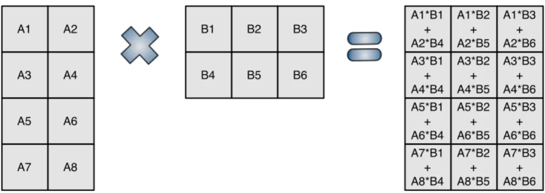
The multiplication of matricesAandB, to produce matrixC, can be divided into smaller computations that operate over different subsets of the original matrices. This promotes parallelism in order to achieve a better performance. In Sequoia, this matrix multiplica-tion can be represented as amatmultask with two variants:
• inner: splits the input matrices into a set of blocks and creates parallel subtasks that compute the partial product of the blocks.
• leaf: performs the matrix multiplication algorithm over the input matrices.
2. STATE OF THEART 2.2. Hierarchical Programming Models
1 v o i d t a s k m a t m u l :: inner (i n f l o a t A [ M ][ P ] ,i n f l o a t B [ P ][ N ] ,
2 i n o u t f l o a t C [ M ][ N ]) {
3 // T u n a b l e p a r a m e t e r s s p e c i f y the size of s u b b l o c k s of A , B , and C .
4 t u n a b l e i n t U ;
5 t u n a b l e i n t X ;
6 t u n a b l e i n t V ;
8 // P a r t i t i o n m a t r i c e s into sets of b l o c k s using r e g u l a r 2 D c h o p p i n g .
9 b l k s e t Ablks = rchop (A , U , X ) ;
10 b l k s e t Bblks = rchop (B , X , V ) ;
11 b l k s e t Cblks = rchop (C , U , V ) ;
13 // C o m p u t e all b l o c k s of C in p a r a l l e l .
14 mappar ( i n t i =0 to M /U , i n t j =0 to N / V ) {
15 mapreduce ( i n t k =0 to P / X ) {
16 // I n v o k e the m a t m u l task r e c u r s i v e l y on the s u b b l o c k s of A , B , and C .
17 m a t m u l ( Ablks [ i ][ k ] , Bblks [ k ][ j ] , Cblks [ i ][ j ]) ;
18 }
19 }
20 }
Listing 2: matmul::inner task, taken from [FHK+06]
1 v o i d task m a t m u l :: leaf (i n f l o a t A [ M ][ P ] , i n f l o a t B [ P ][ N ] ,
2 i n o u t f l o a t C [ M ][ N ]) {
3 // C o m p u t e m a t r i x p r o d u c t d i r e c t l y
4 f o r ( i n t i =0; i < M ; i ++)
5 f o r ( i n t j =0; j < N ; j ++)
6 f o r ( i n t k =0; k < P ; k ++)
7 C [ i ][ j ] += A [ i ][ k ] * B [ k ][ j ];
8 }
Listing 3: matmul::leaf task, taken from [FHK+06]
Thematmul::innertask variant performs a two-dimensional chopping over the input
matrices. The programmer can use thetunablevariables in order to control the amount of data that composes a matrix block, in order to adapt the application for a given memory hierarchy. The produced sets of blocks will be assigned to parallel subtasks in themappar construct, which contains in its body amapreduceconstruct that is necessary in order to reduce, through asumoperation, the results of subtasks upon which a given block of C depends.
The matrix multiplication operation is performed by thematmul::leafvariant, which should be choosen for execution when further task divisions would no longer provide better expected results in the the memory hierarchy.
Configuration In addition to programming the tasks required to carry on the compu-tation, the programmer also has to define a configuration for the application, relative to the target memory hierarchy, in order to optimize its execution for the latter. Listing 4 presents a configuration to efficiently execute the matmul task in a cell processor.
2. STATE OF THEART 2.2. Hierarchical Programming Models
Figure 2.2: Matmul::inner decomposition into subtasks, taken from [FHK+06].
matmul::leafvariant executed.
The values assigned to tunable variables U, X and V are defined so that a matmul working set entirely fits the L1 cache level, which leads to a better performance since cache locality is maximally exploited during the execution of each task.
Irregular Parallelism In the previous examples, as well as the reasoning behind the Sequoia principles, parallelism is assumed to be regular. Parallelism is regular if and only if the two following conditions are met:
• The working set of each subtask is known in advance: All of the inputs of a task have to be known at the time it is invoked. Also, in order to guarantee that the invoked task has enough space to finish its computation, it is necessary to know at least an upper bound for the size of the task’s result;
• The number of subproblems in a task is known beforehand: The number of par-allel subtasks is fixed upon entry on themapparconstruct. Control can only return to the parent task once all the subtasks finish executing.
Irregular parallelism may arise in two common situations:
• A task requires only a small portion of a large data set, therefore due to performance reasons the task should be given only the aforementioned portion.
2. STATE OF THEART 2.2. Hierarchical Programming Models
1 i n s t a n c e {
2 name = m a t m u l _ c l u s t e r _ i n s t
3 v a r i a n t = m a t m u l :: inner
4 r u n s _ a t = c l u s t e r _ l e v e l
5 calls = m a t m u l _ n o d e _ i n s t
6 t u n a b l e U =1024 , X =1024 , V =1024
7 }
8 i n s t a n c e {
9 name = m a t m u l _ n o d e _ i n s t
10 v a r i a n t = m a t m u l :: inner
11 r u n s _ a t = n o d e _ l e v e l
12 calls = m a t m u l _ L 2 _ i n s t
13 t u n a b l e U =128 ,X =128 ,V =128
14 }
15 i n s t a n c e {
16 name = m a t m u l _ L 2 _ i n s t
17 task = m a t m u l :: inner
18 r u n s _ a t = L 2 _ c a c h e _ l e v e l
19 calls = m a t m u l _ L 1 _ i n s t
20 t u n a b l e U =32 ,X =32 ,V =32
21 }
22 i n s t a n c e {
23 name = m a t m u l _ L 1 _ i n s t
24 task = m a t m u l :: leaf
25 r u n s _ a t = L 1 _ c a c h e _ l e v e l
26 }
Listing 4: Matrix multiplication task configuration for a Cluster, taken from [FHK+06].
Sequoia constructs that support irregular parallelism are proposed in [BCSA11], namely thecall-upandspawnconstructs. TheCall-upconstruct provides subtasks with access to their parent task’s heap, which can be used to modify data structures in the latter. Since a task typically launches multiple subtasks, thecall-upconstruct introduces concurrency into the Sequoia programming model.
Spawn is a parallel construct that takes two arguments: a task call and a termination test. A spawn invocation may launch an arbitrary number of subtasks of the provided task call during its execution. The spawn construct terminates and moves computation into after its scope when two conditions are met: the termination test evaluates true, and all subtasks have finished executing.
2.2.2 Hierarchically Tiled Arrays
Hierarchically Tiled Arrays (HTA) [BGH+06] were proposed in 2006 as a new program-ming paradigm for expressing parallelism and locality. This new programprogram-ming model relies on a new object type named tiled array. HTA programs are single-threaded pro-grams where parallel computations are represented as array operations.
2. STATE OF THEART 2.2. Hierarchical Programming Models
Figure 2.3: Pictorial view of an Hierarchically Tiled Array [BGH+06].
matrix M, whose contents may be posteriorly assignedhta(M,[1 3 5],[1 3 5])creates a3×3HTA that consists of tiles with2×2elements of M each. Figure 2.4-(a) illustrates this scenario along with the resulting tiles. An HTA may also be created as an empty
Figure 2.4: HTA construction-(a). Mapping of tiles to processors-(b) [BGH+06].
set of tiles by invoking the HTA constructor with the desired number of tiles. Invoking hta(3,3) creates an HTA with3×3, whose contents may be posteriorly assigned.
After creating the desired tile topology, tiles can be distributed across processors with an additional constructor argument, as depicted in Figure 2.4-(b). In the example shown the6×6matrix is mapped on a2×2mesh of processors. The default implementation used in [BGH+06] uses a block cyclic distribution of the HTA tiles, which assigns tile(i, j) to processor(imodn, jmodm)in an×mprocessor mesh.
2. STATE OF THEART 2.2. Hierarchical Programming Models tiles is similar to accessing scalar elements, except that brackets are used instead of paren-thesis, which results in the expressionC{2,1}referring to the lower left tile ofC. Regions that do not respect the tiling ofCcan be accessed using expression likeC(1:2,3:6), which returns a plain standard2×4matrix.
Figure 2.5: HTAs components access [BGH+06].
Communication Operations In HTA programs, communication is expressed using as-signments on distributed HTA. Communication may also be expressed using other HTA operations, such aspermute,circshiftandrepmatoperations.
The permute operation transposes HTAs, altering the shape imposed by previous
tilings. A variant named dpermute exists that performs a transposition solely over the HTA data, keeping the tiling structure.
TheCircular shiftoperation allows a HTA to be circularly shifted, altering its
over-all topology.
Therepmat operation is an important communication operation that allows a HTA,
or part of it, to be replicated across processors.
Application Example: Matrix Multiplication An implementation of the conventional matrix multiplication algorithm using HTA can be observed in Listing 5.
1 f u n c t i o n C = m a t m u l (A , B , C )
2 i f ( level ( A ) == 0)
3 C = C + A * B ;
4 e l s e
5 f o r i =1: size (A ,1)
6 f o r k =1: size (A ,2)
7 f o r j =1: size (B ,2)
8 C {i , j } = m a t m u l ( A {i , k } , B {k , j } , C {i , j }) ;
9 end
10 end
11 end
12 end
2. STATE OF THEART 2.2. Hierarchical Programming Models IfA,BandCare tiled arrays, thematmulfunction can be applied in parallel to each triplet of corresponding tiles using the parHTA function with the matmul function and the ma-trixes to be multiplied as arguments, resulting in the expression:
C = parHTA(@matmul, A, B, C)
Note that the "+" and "*" operators are overridden to represent the scalar matrix mul-tiplication, thereby making sense of the expressionC = C + A * B at line 3. The level function can be used to obtain, at runtime, the location of the given argument within the tile hierarchy, returning 0 for a leaf (scalar matrix) and non-zero for tiles according to their location in the hierarchy. Spatial locality is exploited since processors access data sequentially in each tile.
2.2.3 Hierarchical Place Trees
Hierarchical Place Trees (HPT) [YZGS10] model, developed in 2010 by a team of re-searchers from the Department of Computer Science of the Rice University, aims to over-come the restrictiveness of Sequoia’s communication mechanisms. Communication in Sequoia is limited to parameter passing during function calls.
HPT supports three different types of communication: implicit access, explicit in-out parameters, and explicit asynchronous transfer. In addition, HPT allows dynamic task scheduling, rather than static task assignment as in Sequoia.
Several concepts used in HPT were introduced by the X10 language [CGS+05], namely the concept ofplaceandactivity(task).
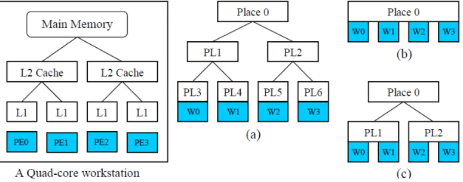
Hierarchical Place Trees Model In the HPT model each memory module is abstracted as aplace, and therefore a memory hierarchy is abstracted as a place tree. Places are tagged with annotations that indicate their memory type and size. A processor core is abstracted as aworker thread, which in the HPT model can only be attached to leaf nodes in the place tree. The removal of this last restriction has been considered in order to accommodateprocessor-in-memoryhardware architectures in the HPT model.
As in X10, a task can be directed to place PLi by using a statement of the formasync (PLi), which should be read as "move the current task to the place PLi asynchronously".
However, unlike X10, the destination place may be a leaf node or a non-leaf node in the hierarchy. If the target of anasyncstatement is a non-leaf place PLi, then the task can be executed on any worker that belongs to the subtree rooted at PLi. A consequence of this constraint is that a worker can only execute tasks from its ancestor places. It is also assumed that if a task is suspended while executing at a workerw0, it can resume its execution at any worker that belongs to the subtree of the task’s original target place.
As an illustrative example, consider the place tree presented in Figure 2.6; a task T assigned to PL1 can only be executed by workersw0orw1. Also, if T is suspended while
2. STATE OF THEART 2.2. Hierarchical Programming Models
Figure 2.6: A Hierarchical Place Tree example, taken from [YZGS10].
Figure 2.7: Three different HPT abstractions a, b and c of the same machine.
Compilation and Mapping to a Real Architecture The steps required to program and execute an application using the HPT Model are not a simple straightforward compila-tion process. A machine-independent compilacompila-tion step handles parallelism and locality, which is abstractly expressed in the program to allow it to work with anyconfiguration specification, which is machine-dependent. The configuration specification consists of an HPT model that represents the desired view of the system, and a mapping of the places and workers in the HPT model onto the memories and processor cores in the target ma-chine. This allows the same program to be executed with different configuration specifi-cations.
It is common to use different configurations as abstractions for different hardware systems, yet it is also possible to use different configurations as alternative abstraction of the same physical machine. Consider the example of Figure 2.7; the model(a)mirrors the machine’s structure, whereas in (b)all the memory is seen as a flat shared memory with uniform access, and in(c)the memory is seen as a two-level memory hierarchy.
2. STATE OF THEART 2.2. Hierarchical Programming Models this, HPT model builds on the idea of a PGAS, extending it with the idea that the parti-tioning is not flat and may occur across a place tree hierarchy. Partitioned Global Address Space (PGAS) is a parallel programming model where a global address space is assumed. In the PGAS model each thread is given a global address space in addition to its local address space, which can be accessed by other threads for communication, thereby pro-viding a powerful abstraction to program distributed applications using shared memory semantics. Figure 2.8 illustrates the PGAS model, showing each thread’s global and local address spaces. As with distributed address spaces, each portion of the global address
Figure 2.8: PGAS Address Space Model [CDC+99].
space has affinity with a given thread, that thread benefits from locality of reference when accessing data in its portion of the address space. Due to performance reasons, data lo-cality is exposed to the programmer.
The HPT model provides three data transfer mechanisms: 1) data distribution with implicit data transfer; 2) explicit copyin/copyout parameters, and 3) explicit asynchronous data transfer.
All data structures that may be accessed implicitly using global addresses are required to have a well-defineddistribution across places. Furthermore, each scalar object is as-sumed to have a singlehome place. Accessing any part of an object results in a data trans-fer from the home place to the worker that is going to perform the access; the access cost will depend on the distance between the home place and the worker.
Data can also be explicitly synchronously transferred usingIN,OUTandINOUT, analo-gous to a dataflow model. When a task is launched at its destination place, data specified
byINandINOUTclauses will be copied into the temporary space of the destination place.
Once the task finishes its execution, the data specified by theOUTandINOUTparameters will be copied back to their original locations.
2. STATE OF THEART 2.2. Hierarchical Programming Models
2.2.4 Hierarchical SPMD
Early work that shares our concerns regarding the limitations of the SPMD model and the tuning of parallel applications according to the target hierarchy is first presented in [KY14]. The author also mentions the limitations of the Sequoia model, namely the lack of more powerful communication mechanisms that was also addressed in Section 2.2.3, as well as its intrusion to the programmer, who is obliged to provide hierarchical mappings and tunable configurations for its programs.
Hierarchical Thread Teams One of the most important concepts introduced in Hier-archical SPMD (HSPMD) is that of a team of threads, which was presented in [KY12]. Figure 2.9 shows a thread team hierarchy that results from the division of a initial team of 12 threads labeled from 0...11 into 3 teams, with each subteam being further divided into two uneven teams, with 3 threads and a single thread respectively. Thread teams are supported by additional linguistic constructs for expressing data decomposition among them.
Figure 2.9: Team hierarchy example [KY12].
Task Decomposition When implementing a task parallel program, different parts of an algorithm may be assigned to different threads. Thepartitionstatement is introduced as a syntactic construct to assign tasks to different subteams of threads:
partition(T){B0B1... Bn−1}
whereTrepresents a thread team and each subteam ofTis assigned a different codeblock Bxfor execution. Once a subteam finishes executing a partition branch, it rejoins the pre-vious thread team. Execution only moves to the code after the partition statement, with the whole team, when all the subteams executing the codeblocks finish their execution.
2. STATE OF THEART 2.2. Hierarchical Programming Models Theteamsplitstatement, with the following syntax, allows a data centred decomposi-tion to be expressed:
teamsplit(T)B
Once again T represents a team of threads and the construct causes each thread team inT to execute the codeblock B. Each thread belonging to a subteam tof T executes in the context oft, which means that the thread identifier obtained using the invokation Ti.thisProc ()is its offset int.
An interesting motivational example for the teamsplit construct is the implementa-tion of the shared memory sort algorithm. In the shared memory sort algorithm, data is evenly distributed amongst the available threads and each thread executes the sequential quicksort over its own data. The sorted subsets are then merged in parallel in multiple phases, with the number of threads executing the merge being halved in each phase. Figure 2.10 illustrates this algorithm executing with four threads.
Figure 2.10: Shared memory sorting algorithm using four threads [KY12].
Using a team hierarchy structured as a binary tree, the recursive nature of the sorting can be intuitively expressed. Listing 6 presents thedivideTeamfunction that creates such hierarchy.
1 s t a t i c v o i d d i v i d e T e a m ( Team t ) {
2 i f ( t . size () > 1) {
3 t . s p l i t T e a m (2) ;
4 d i v i d e T e a m ( t . child (0) ) ;
5 d i v i d e T e a m ( t . child (1) ) ;
6 }
7 }
Listing 6: DivideTeam method, taken from [KY12].
2. STATE OF THEART 2.2. Hierarchical Programming Models
1 s t a t i c s i n g l e v o i d s o r t A n d M e r g e ( Team t ) {
2 i f ( Ti . n u m P r o c s () == 1) {
3 a l l R e s [ m y P r o c ] = S e q S o r t . sort ( m y D a t a ) ;
4 } e l s e {
5 t e a m s p l i t( t ) {
6 s o r t A n d M e r g e ( Ti . c u r r e n t T e a m () ) ;
7 }
8 Ti . b a r r i e r () ; // e n s u r e prior work c o m p l e t e
9 i f ( Ti . t h i s P r o c () == 0) {
10 i n t o t h e r P r o c = m y P r o c + t . child (0) . size () ;
11 i n t[1 d ] myRes = a l l R e s [ m y P r o c ] ;
12 i n t[1 d ] o t h e r R e s = a l l R e s [ o t h e r P r o c ] ;
13 i n t[1 d ] n e w R e s = t a r g e t ( t . depth () , myRes , o t h e r R e s ) ;
14 a l l R e s [ m y P r o c ] = merge ( myRes , o t h e r R e s , n e w R e s ) ;
15 }
16 }
17 }
Listing 7: Shared memory sort implementation with thread teams, taken from [KY12].
Figure 2.10.
2.2.5 Unified Parallel C
UPC [CDC+99] is a parallel extension of the C programming language ISO C99 that adopts the SPMD programming model with a PGAS address space. Hierarchical ad-ditions to the UPC language are proposed in [WMEG11].
The authors recognize that, although compiler and runtime optimizations increase the efficiency of a program up to a certain degree, when dealing with architectures with complex memory hierarchies the greatest performance gains can only be attained by op-timizing the way the application uses these hierarchies. However, the increasing levels of the hardware hierarchy and the wide variety of system architectures make it difficult for compilers to perform efficient tunnings. Therefore, it is highly unlikely that compiler or runtime systems will perform a good distribution of data and tasks across the hier-archy to meet the user’s computational needs. This means that one should emphasize enhancements of the programming model as much as improving the compiler or run-time libraries.
Two complementary approaches to manage and express hierarchical parallelism at the application level are studied in the paper.
2. STATE OF THEART 2.2. Hierarchical Programming Models During runtime, the location of a thread within the hardware topology can be re-trieved using a specific thread layout query function. Though the resolution is low, the function can accurrately distinguish between a remote and a local thread. This func-tionality allows a programmer to explicitly identify which UPC threads share the same physical address space, enabling optimizations in the access to neighbours’s shared ar-rays and henceforth.
Approach 2: UPC/sub-threads Hybrid Model The second approach proposes the di-rect addition of nested parallelism in UPC using sub-threads. Sub-threads are layered on each SPMD UPC thread and execute within the same partition of the shared address space as the corresponding master thread.
Although this model is similar to the hybrid MPI/threads model, differences exist that set these two models apart:
• Sub-threads in UPC can access remote distributed memory directly using the global address space;
• Global shared arrays are the primary constructs for parallel programming.
UPC sub-threads represent a new level of parallelism that allows the natural parallelism of algorithms to be captured, as UPC programs no longer have to cope with a single-level of execution. Moreover, sub-threads allow local computational resources to be fully exploited in distributed UPC applications.
2.2.6 Fractal Component Model
Hierarchical organization of parallel systems can also be found at integration level. The Fractal model [BCL+06] is a powerful component programming model for diverse com-plex applications. One of Fractal’s most relevant features in the context of hierarchical parallelism is its composition model. Figure 2.11 illustrates some examples of Fractal components.
The componentAis a primitive component since it is not internally composed by any other component. On the other hand,Cis a composite component since it is composed by other components that attend different server ports. The sub-components can them-selves be primitive, composite or parallel components. FinallyDis a parallel component because its components do not connect between themselves, attend to the same server port, and output to different client ports.
We can observe that the Fractal composition model allows complex parallel compo-nent hierarchies to be created. As an example of a real world application modelled using Fractal components, consider the graphical 3D renderer depicted in Figure 2.12.
2. STATE OF THEART 2.2. Hierarchical Programming Models
Figure 2.11: Fractal component types examples, taken from [BBC+06].
2. STATE OF THEART 2.3. Hierarchical Work Distribution output and a server port to receive the input from the Renderers. The Renderers them-selves are represented as a parallel component with 4 sub-components R1 to R4. From the Dispatcher’s point of view, the Renderers function as a primitive component with a client port and a server port, with the Renderer’s inside being a black box.
The Fractal model was later instanced in the ProActive [BBC+06] middleware, in the context of its parallel implementation. Component hierarchies are defined using a XML framework.
2.3
Hierarchical Work Distribution
Distributing parallel tasks across processors, in a way that maximally exploits locality of access to data, is not the only concern to have into account when optimizing the execu-tion of parallel applicaexecu-tions. There is space for optimizaexecu-tions regarding communicaexecu-tion amongst tasks and the even distribution of computation across the available hardware resources, so as to prevent unnecessary high latency communication and idle times on computational resources, respectively.
The paper entitled "Hierarchical Mapping for HPC Applications" [CLZC11], pub-lished recently in 2011, addresses the problem of distributing tasks of a parallel appli-cation onto physical processors of a computational architecture in a way that not only minimizes the communication costs, but also evenly distributes the computation across the processors.
In this paper an algorithm called "Hierarchical Mapping Algorithm" (HMA) is pre-sented, which given a hardware physical topology modeled as a graph, approximates the optimal distribution of tasks across the topology with the aforementioned concerns in mind. HMA provides better scalability than the static mapping method, which maps tasks into computational resources based on static information. Such method requires a large amount of detailed analysis that can be impraticable both in terms of design com-plexity and execution time, and also requires the decomposition of the problem and the topology of the host machine to be known beforehand.
The HMA targets large-scaled applications and uses the hierarchical mapping ap-proach. Instead of using static information, HMA builds a graph representative of the parallel tasks and communication based on profile information collected using the MPI tracing tool. The algorithm was designed to support complex systems, therefore it can handle:
• applications with irregular parallelism or complex communication patterns;
• computing systems with high dimensional interconnection;
• mapping efficiency in large scale computing systems.
2. STATE OF THEART 2.4. Discussion
Supernodes An important concept of the HMA is that of a supernode. Supernodes are nodes in the hierarchy topology graph where tasks with strong relations are placed. In the initial mapping phase, "supernodes" are mapped onto the host machine.
For a givenk, the task partitioning part of the HMA algorithm clustersV intokgroups that form the set of supernodes{A1, A2, ...Ak}.
Graph Construction Before executing the algorithm, a weighted graph G(V, E, w) is built based on profile information collected during run-time using the MPI tracing tool. V is a set of tasks,E represents the communication relations between tasks, andw(u, v) corresponds to the message size exchanged between the tasksuandv.
Task Partitioning During task partitioning the algorithm has two objectives. The first objective is thecohesion criterion, which asserts that the communication traffic within a su-pernode has to be higher than traffic between susu-pernodes, thereby reducing the amount of high latency communication. Second, there is theequality criterion, which means that the size of each supernode should be as equal as possible.
Initial Mapping The initial mapping places all supernodes onto the same target host machine. Then the algorithm resumes its execution with the criterion of minimizing the communication costs among supernodes.
Fine Tuning Last in the HMA execution flow, the fine tuning phase employs various optimization techniques that include the simplex method, the local search method, or the simulated annealing, so as to improve the mapping generated during the initial mapping phase.
2.4
Discussion
In the presence of multiple CPU cores, the most straightforward approach is to perform a horizontal decomposition of the domain, splitting the original dataset into as many partitions as the number of available workers.
Although this approach makes use of the parallelism available on the underlying hardware architecture, it is based solely on the number of cores available in the machine. Nonetheless, there are other traits that differentiate a particular architecture from others featuring the same number of cores, namely its cache hierarchy. To fully harness the computational power of a machine, one has to employ a decomposition strategy that takes these hardware differences into account.
2. STATE OF THEART 2.4. Discussion The presented state-of-the-art approaches present both means to model machines, and to employ vertical decomposition, namely how to express it and program applica-tions in a machine-independent manner.
The Sequoia language introduced the concept of task variants and tunable variables, which along with a mapping specification provided by the programmer tune applications according to the target machine(s).
HPT proposes modelling a system as a place tree and its processor cores as workers attached to the leaves of the former, defining a view of the system. This view is subse-quently mapped onto a real machine according to a configuration specification, provided by the programmer.
3
Hierarchical Domain Decomposition
Domain decomposition is the most common and natural of parallel decomposition strate-gies in data-parallel computing. It consists on decomposing the original domain of an operation into several partitions upon which different instances of the original operation can be applied in a parallel fashion.
Chapter 2 presented the most recent efforts on hierarchical parallelism, and its ver-tical take on domain decomposition. Common to all the presented approaches is the additional burden they require from the programmer, in order to exploit vertical decom-position, namely the mapping of applications onto the target machine’s hardware. The programmer is therefore required to have knowledge of the hardware in hands, whereas its focus should rely solely upon the application’s logic and data manipulation. Hence, we believe that it is possible to automatically employ a vertical decomposition approach that:
1. determines the optimal size for partitions of the original domain, to be assigned to each individual task;
2. partitions the original domain into partitions with the pre-determined size;
3. orchestrates the whole execution from the invocation of the original operation to the obtainal of its final result.
3. HIERARCHICALDOMAINDECOMPOSITION 3.1. Data-size Driven Decomposition
3.1
Data-size Driven Decomposition
When decomposing a domain Dinto a set P of partitions that fit a given target cache level (TCL), one wants to find a numberN of partitions into whichDcan be partitioned so that the following property holds:
∀p∈P, size(p) = size(D)
N ≤size(T CL) (3.1)
For that sake of generality, we assume that the original domain Dmay itself be the re-sult of composition of multiple subdomainsD0, ..., Dn−1. For instance, in the classic
ma-trix multiplication, one can implement a decomposition strategy that decomposed the 3 matrices involved, or decomposed the 3 individually and have a way of combining the resulting individual partitions. To accommodate the latter case, formula 3.1 has te be refined to
∀p∈P, size(p) =
n−1
X
i=0
size(Di)
N ≤size(T CL) (3.2)
It is not always possible to achieve such a obvious solution. To that fact mostly con-tributes the fact that even thoughsize(D)may be a multiple ofN, a non-zero remainder
Ri = size(Di) modN may exist for some sub-domainDi. In these situations, one may
either produce a smaller dataset of sizeRi, preserving property 3.2, or one may choose to distribute the bytes ofRamongst the regular-sized partitions, which may afterwards contain more bytes than the size of the TCL, violating the property. The first solution can not be applied if a non-zero remainderRi exists only for some sub-domains ofD, which would cause a different number of partitions to be produced from each sub-domain.
Problem-specific constraints may impose further restrictions upon the number of par-titions and/or the geometry of the decomposition as a whole. Stencil computations present this kind of restrictions, both in terms of the number of elements and the ge-ometry of a partition. Astencilcomputes an element in an-dimensional grid at timetas a function of adjacent elements of the grid at timet−1, ..., t−k. Consider a simple stencil computation that computes the value of an element(i, j)in the grid at timet1as
g1i,j =
g0i,j
2 +
g0i+1,j
16 +
g0i−1,j
16 +
g0i,j−1
16 +
g0i,j+1
16 +
g0i+1,j+1
16 +
g0i−1,j+1
16 +
g0i+1,j−1
16 +
g0i−1,j+1
16
where g0andg1denote the grid at timet0 andt1 respectively. Corner cases (elements
without 8 adjacent elements) are computed using different weights for the adjacent val-ues.
The value of an element at timet1is a function of the values of its 8 adjacent elements
plus itself at timet0. Therefore, each partition is required to have at least 9 elements and
3. HIERARCHICALDOMAINDECOMPOSITION 3.1. Data-size Driven Decomposition
a b
t
0Figure 3.1: Invalid (a) and valid (b) Stencil Partitions
illustrates an invalid (a) and a valid (b) partition ofg0. Note that the computation to be applied to each partitionpofg0only produces a result (to be placed ing1) for the inner elements ofp.
This kind of information must be supplied in the decomposition algorithms supplied by the programmer, and is therefore included in the interface that regulates the imple-mentation of such algorithms (Listing 8). Method getAverageLineSize is of particular relevance. It validates whether the dataset may be split into the supplied number of par-titions, and, when such condition holds, returns the average size (in number of elements) of the first dimension of such partitions. We are assuming a row-major order memory layout, which is typically the case in most programming languages, including Java, in which we implemented our proposal. This information is therefore relevant to under-stand the decomposition of a partition into cache lines. The use of the average value conveys some extra information to the system when the size of the partitions is irregu-lar. This situation may occur, for instance, in the aforementioned situation, where the remainder R is positive and one chooses to distribute these bytes across regular-sized partitions.
3. HIERARCHICALDOMAINDECOMPOSITION 3.1. Data-size Driven Decomposition 1 p u b l i c i n t e r f a c e D i s t r i b u t i o n <T > {
3 /* *
4 * P a r t i t i o n s the input d o m a i n into n P a r t s p a r t i t i o n s .
5 * @ p a r a m n P a r t s the n u m b e r of p a r t i t i o n s to be p r o d u c e d
6 * @ r e t u r n the p a r t i t i o n s
7 */
8 T [] p a r t i t i o n (i n t n P a r t s ) ;
10 /* *
11 * R e t u r n s the a v e r a g e size of a p a r t i t i o n of T ( in n u m b e r of e l e m e n t s )
12 * @ r e t u r n size of P
13 */
14 f l o a t g e t A v e r a g e P a r t i t i o n S i z e (i n t n P a r t s ) ;
16 /* *
17 * R e t u r n s the a v e r a g e size of line of a p a r t i t i o n of T ( in n u m b e r of e l e m e n t s )
18 * @ r e t u r n size
19 */
20 f l o a t g e t A v e r a g e L i n e S i z e (i n t n P a r t s ) ;
22 /* *
23 * R e t u r n s the size of an e l e m e n t of T ( in bytes )
24 * @ r e t u r n size
25 */
26 i n t g e t E l e m e n t S i z e () ;
27 }
Listing 8: TheDistributioninterface
for each core sharing a TCL, calculated asT CL_SIZE/CORES_P ER_T CL.
Accordingly, the number of partitions (nP arts), into which each domain can be de-composed, ranges from the number of workers assigned to the execution (nW orkers) up to a value n that represents a valid solution, meaning that should each domain Di be decomposed intonpartitions all these would fit the TCL. Values ofnP artslower than the number of available workers are not considered since these would not fully exploit the parallelism available on the machine. Although this prevents any single worker from having no tasks to execute, it does not guarantee that the number of tasks assigned to each thread is evenly balanced. This kind of will be discussed in Section 3.2.
Since the size of each individual partition decreases with the increase of nP arts, which is continuously incremented in each iteration, the first valid value of nP artsis the optimal solution, that is, each partition has the maximum size that fits the TCL.
Central to the algorithm is the computation of the size of each individual partition that compose a working set (lines 5 to 9). The procedure starts by invoking the method
getAverageLineSizeto validate the current value ofnP arts. Depending on the returned
value, a different course of action is taken. Value 0 invalidates the current value ofnP arts as a solution, causing the algorithm to procede to the next value.
A negative answer invalidates the current proposal fornP arts, as well as any value
n′ > nP artscausing the algorithm to stop since no valid solution will be found. When
![Figure 2.1: Memory Hierarchies examples, taken from [ACF93].](https://thumb-eu.123doks.com/thumbv2/123dok_br/16529955.736265/26.892.252.594.129.492/figure-memory-hierarchies-examples-taken-from-acf.webp)
![Figure 2.2: Matmul::inner decomposition into subtasks, taken from [FHK + 06].](https://thumb-eu.123doks.com/thumbv2/123dok_br/16529955.736265/31.892.286.648.137.458/figure-matmul-inner-decomposition-into-subtasks-taken-from.webp)
![Figure 2.11: Fractal component types examples, taken from [BBC + 06].](https://thumb-eu.123doks.com/thumbv2/123dok_br/16529955.736265/42.892.204.647.199.513/figure-fractal-component-types-examples-taken-from-bbc.webp)