Review of Generation-III/III+ Fission Reactors
CHAPTER · JANUARY 2011 DOI: 10.1002/9781118043493.ch22
CITATION
1
READS
394
1 AUTHOR:
J.G. Marques
Technical University of Lisbon
164PUBLICATIONS 1,016CITATIONS
SEE PROFILE
22
REVIEW OF GENERATION-III/III+ FISSION REACTORS
J.G. Marques
Instituto Tecnol´ogico e Nuclear & Centro de Fisica Nuclear da Universidade de Lisboa, Portugal
22.1 INTRODUCTION
The nuclear power industry has been developing and improving reactor technology over five decades. Several generations of reactors are commonly distinguished. The reactors in operation today were mostly built in the 1970s and 1980s. They are considered Generation II reactors, because they are based on the experience gained with the Generation I reactors built in the 1950s and early 1960s. The accumulated operating experience to the present time with current reactors exceeds 14,000 reactor-years [1]. Building of Generation III reactors started in the early 1990s, with improved safety and economics, while Generation III+ reactors include further developments. We will refer to Generation III and III+ reactors simply as Gen III/III+ in this review. Generation IV designs are still on the drawing board, and it will take two to three decades for them to be operational.
Gen III/III+ designs present a set of distinctive charac-teristics [2–4]:
• simpler and more rugged design, making the reactors easier to operate and less vulnerable to operational disturbances.
• Greater use of passive safety features that require no
active controls and rely on natural phenomena.
• Reduced probability of occurrence of accidents
involving core melting.
• New mitigation measures in case of core melt accidents, in order to reduce significantly the impact of such accidents to the environment and to the public.
Nuclear Energy Encyclopedia: Science, Technology, and Applications, First Edition (Wiley Series On Energy). Edited by Steven B. Krivit, Jay H. Lehr, and Thomas B. Kingery.
2011 John Wiley & Sons, Inc. Published 2011 by John Wiley & Sons, Inc.
• Resistance to the impact of a large aircraft.
• Standardized designs, able to reduce licensing and construction time, as well as capital cost.
• Longer time interval between refueling, resulting in a higher availability.
• Higher burnup to increase fuel use and reduce the amount of waste produced.
• Longer operating lifetime, 60 years, already from
design.
Table 22.1 shows the main Generation III/III+ designs constructed, under construction, or undergoing pre-licensing/licensing procedures [3, 5], in alphabetical order by their abbreviation. The characteristics of these reactors will be presented below, divided in the categories of Pres-surized Water Reactors (PWR), Boiling Water Reactors (BWR), Pressurized Heavy-Water Reactors (PHWR), and High-Temperature, Gas-cooled Reactors (HTGR), after a general presentation of relevant features of Gen III/III+ designs with their impact on safety and economic aspects.
22.2 SAFETY FEATURES OF GENERATION III/III+ FISSION REACTORS
The safety of nuclear fission reactors has always been an important issue. Redundancy and diversity are commonly applied principles for tolerance against faults that can be traced back to the first reactor built by Fermi in 1942 [2]. Gen III/III+ designs have an increased reliance on passive systems, when compared with designs of previous
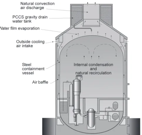
TABLE 22.1 Main Gen III/III+ Reactor Designs
Net Electric
Reactora Developer(s) Output(MW
e) Typeb Status
ABWR General Electric, Toshiba, Hitachi 1315 BWR Start of operation in Japan, 1996 ACR-1000 Atomic Energy of Canada 1085 PHWR Start of operation in Canada, 2016c
AES-92 Gidropress 1000 PWR Start of operation in India, 2011c
AP1000 Westinghouse 1117 PWR Start of operation in China, 2013c
APR-1400 Korea Hydro & Nuclear Power 1350 PWR Start of operation in South Korea, 2013c
APWR Mitsubishi 1600 PWR Start of operation in Japan, 2017c
EC6 Atomic Energy of Canada 700 PHWR Design certification ongoing in Canada
EPR Areva 1600 PWR Start of operation in Finland, 2012c
ESBWR General Electric Hitachi 1333 BWR Design certification ongoing in the US GT-MHR General Atomics and others 280 HTGR Start of operation in Russia, 2021c
IRIS Westinghouse and others 335 PWR Design certification in the US to start in 2012c NuScale Nexant-Bechtel and others 35 PWR Design certification in the US to start in 2012c
SWR-1000 Areva 1250 BWR Compliance with European requirements, 2002
aACR-1000 and EC6 are registered trademarks of Atomic Energy of Canada Limited; AP1000 is a trademark of Westinghouse Electric Company, LLC;
APR1400 is a trademark of Korea Hydro & Nuclear Power Company; EPR and SWR-1000 are trademarks of the Areva Group.
bBWR=Boiling Water Reactor; PHWR=Pressurized Heavy Water Reactor; PWR=Pressurized Water Reactor; HTGR=High Temperature Gas-cooled Reactor.
cExpected.
generations. The use of passive systems circumvents the eventual disruption of external sources of electricity, cooling water, and other essential supplies following an extreme event. Several Gen III/III+ designs provide for the physical presence of large thermal capacity heat sinks available to cool the reactor core without depending on the availability of externally powered pumps, relying rather on cooling by natural convection, radiation, and conduction. When valves are required for the activation of passive safety systems, they are generally “fail safe,” because they require power to stay in their normal, closed position, and loss of power causes them to open; their movement is made using stored energy from compressed gas, batteries, or springs.
Gen III/III+ designs are characterized by a reduced probability of occurrence of accidents involving core melting, quantified by a Core Damage Frequency (CDF). The International Atomic Energy Agency (IAEA) issued
its Basic Safety Principles for Nuclear Power Plants in
1988, prepared by an INternational Safety Advisory Group (INSAG) [6], which recommended that the CDF value for advanced designs should not exceed 1×10⁻⁵ events
per reactor-year. This recommendation represented an improvement of a factor of 10 over the U.S. Nuclear Regulatory Commission (NRC) requirement for the CDF of current plants to be below 1×10⁻⁴ events per
reactor-year. The INSAG recommendation has been widely adopted both by utilities and manufacturers for new nuclear power plants.
Figure 22.1 shows a graphical representation of CDF values (in events per reactor-year) for typical Gen III/III+
PWR and BWR designs, compared with the NRC require-ment for current plants, a typical value for current plants, and the INSAG limit. The CDF value taken as representa-tive for current plants is 5×10⁻⁵ events per reactor-year,
even if this is subjected to large variations by design and country [7]. The CDF for new designs is typically two to three orders of magnitude below the INSAG limit. Gen III/III+ BWR designs tend to have a smaller CDF than PWR designs, as already happens for current reactors [7]. Spe-cific CDF values for Gen III/III+ designs will be presented later.
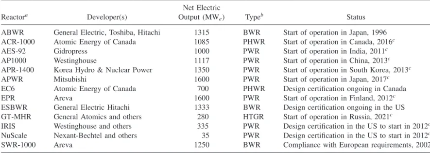
A core melt does not necessarily lead to a large radioac-tive release from the reactor. The INSAG recommended that severe accident management and mitigation measures should reduce by a factor of at least 10 the probability of large off-site releases requiring short-term off-site response [6], and this has been systematically taken into account in new reactor designs [8]. The provision in several reactors to cool and contain the corium, i.e., the molten fuel-structure mixture resulting from a core melt, is a significant contrib-utor for this reduction.
Corium cooling is essential, since the release of fission products and the generation of non-condensable gas stop as the melt/debris temperature drops below approximately 1000◦C [9]. The cooling and contention are achieved in Gen III/III+ designs by ex-vessel or in-vessel structures, represented schematically in Figure 22.2.
Figure 22.1 Graphical representation of the core damage frequency (in events per reactor-year) for typical PWR and BWR Gen III/III+reactor designs, compared with the NRC limit for current reactors, the INSAG-3 limit for advanced reactors, and a typical value for current plants. The volume of each cube is proportional to the core damage frequency.
Figure 22.2 Simplified representation of ex-vessel and in-vessel corium cooling and retention systems.
confinement, it is necessary to avoid an attack of the molten core on the containment basemat. An ex-vessel core catcher increases the surface-to-volume ratio of the melt after its release from the reactor pressure vessel (RPV) and allows for the effective quenching and stabilization of the melt before it can attack the structural concrete. The corium in the core catcher can be cooled passively or actively. The deliberate interaction with sacrificial materials (concrete or oxide materials) on a first layer helps to cool the corium and to keep it liquid over a wider temperature range, so that it spreads efficiently. The use of non-limestone aggregate concrete (so called basaltic concrete) minimizes further production of carbon-based non-condensable gases, such as CO and CO2, which could contribute to eventual
containment failure.
The basic idea of in-vessel retention of corium is to prevent RPV melt-through by flooding the reactor cavity and transferring the decay heat from the corium on the lower head of the RPV to the water surrounding the vessel [10]. This heat transfer must be efficient so that the RPV wall maintains its structural properties and is able to support the mechanical load that results from the weight of the corium and the lower head and from possible pressure inside the vessel. The RPV thus maintains its function as a
barrier against the release of fission products. An obvious advantage of this type of corium retention scheme is the fact that all ex-vessel phenomena are avoided, such as direct containment heating, corium-concrete interactions, and eventual steam explosions [9]. The first structure of this type was approved by the Finnish Radiation and Nuclear Safety Authority (STUK) for the Loviisa plant, equipped with Russian VVER-440 reactors [11].
22.3 ECONOMIC FEATURES OF GENERATION III/III+ FISSION REACTORS
Most nuclear power plants built in the past were one of a kind. The concept of standardized design entered this field only toward the end of Generation II, but it is firmly established in Gen III/III+ designs. Standardization has a direct impact on reducing licensing time, construction time, and capital costs, as well as exploitation costs. Currently, the NRC approves a nuclear power plant design (the so-called Design Certification”), independent of an application to construct or operate it. By issuing a Combined Operating License (COL), the NRC then authorizes a given licensee to construct and operate a nuclear power plant at a specific site, with specified conditions, in accordance with established laws and regulations. In this way, the utilities benefit from the previous certification of a given standard reactor design [13]. Several other regulatory authorities follow similar procedures. As an example of another impact of standardization, a systematic decrease (from 75 to 61 months) was observed of the time from start of civil works to connection to the grid of French REP-900 reactors (PWR, 900 MWe), as construction of this series
progressed [14].
Plant lifetime is ultimately limited by the lifetime of the RPV, which is normally the only component that is not replaceable. As a result of the irradiation with fast neutrons released from the fuel, the RPV steel can become more brittle (reduced ductility and fracture toughness) in certain areas [15]. The important factors governing radiation embrittlement of the RPV are the sensitivity of the steel to embrittlement, the neutron fluence and energy spectrum, and the irradiation temperature [16]. The major contributors to the sensitivity to embrittlement (i.e., copper and phosphorus impurities, as well as high nickel content) were revealed in the early 1970s, and the specifications of the steels were correspondingly updated [17]. The neutron emission may be reduced to some extent all around the core or just at the “hot spots” by tailored core-loading patterns. Other measures to decrease the neutron irradiation of the RPV are the implementation of a larger water gap between the core and the inner wall of the vessel or the use of a neutron reflector [18]. The neutron reflector has the added advantage that it increases the neutron fraction that is available to take part in the chain reaction and can thus improve fuel utilization. Studies carried out in several countries have indicated that the RPV of current reactors can remain in safe operation for a period of at least 50 to 60 years for most designs [19]. Gen III/III+ reactors take full advantage of this accumulated knowledge in order to have a vessel lifetime of 60 years already from design, keeping the fast neutron fluence well below 1019 n/cm2.
The availability of the plants should, naturally, be as high as possible. This is achieved, namely, through a reduction in the number of unplanned outages, an increase in the maintenance that can be done with the reactor running, a reduction in the time needed to refuel the reactor,
and an increase in the time between successive refueling operations. Gen III/III+ designs feature refueling intervals up to 24 months, while the typical value for previous generations is 12 months. In 2008, 16 reactors achieved an energy availability factor of 100% (this indicator is defined as the ratio between the net electrical energy supplied by the reactor and the one that would have been supplied for a continuous operation at the reference unit power, during a given period). From these 16 reactors, 12 were in the United States, two in Japan, one in Korea, and one in Taiwan [20]. High availability values are not an exclusive of countries with a large infrastructure: The only plant in Slovenia, Krsko, achieved an energy availability factor of 98.6% in 2008, with an average energy availability factor of 95.2% from 2004 to 2008 [20].
Figure 22.3 shows the worldwide evolution of the median value of the energy availability factor in the last three decades, using values from the PRIS database [21] of the IAEA, compared with the expected value for Gen III/III+ reactors. The median availability factor has increased significantly in this period, from 74% to 86%. The best quartile also increased significantly from 83% to 92%. All Gen III/III+ designs have a planned availability factor above 90%, averaged over the lifetime of the plant.
Fuel burnup should, in principle, be as high as feasible. Figure 22.4 shows the evolution of average fuel burnup achieved worldwide for both BWR and PWR reactors in the last three decades, using data from Watteau and co-authors [22], compared with the expected values for Gen III/III+ reactors. Although burnup values have increased significantly in this period, recent studies show that there
Figure 22.4 Evolution of fuel burnup for BWR and PWR reactors in the last three decades and expected values for Gen III/III+ reactors. The values for current reactors were obtained from Watteau and co-authors [22].
is little economic gain in increasing the burnup above 60 MWd/kgHM with the current fuel cycles [23], even if this would be technically feasible. A significant number of Gen III/III+ designs are expected to approach this burnup value; further improvements are only expected with Generation IV reactors, using different fuels and fuel cycles [24].
Table 22.2 presents a set of general characteristics of Gen III/III+ reactor designs. Details and references on the values for the different designs are given in the text below.
22.4 GENERATION III/III+ PRESSURIZED WATER REACTORS
PWRs have their origins in the technology developed for the nuclear submarine program of the U.S. Navy [25, 26]. The U.S. Atomic Energy Commission sponsored the development of the 90 MWeShippingport PWR, completed
in 1957, while the first commercial PWR, Yankee Rowe
(167 MWe), was completed in 1960. The first Russian
PWR started operating in 1964; it was a VVER-210 prototype (Novovoronezh-1), with 210 MWe power. It
was followed in 1969 by a 365 MWe unit, a VVER-365
prototype (Novovoronezh-2) [27, 28].
PWR is the most popular design, with 264 units out of a total of 438 units in operation at the end of 2008, having provided nearly two-thirds of the integrated power throughout the world in that year [29]. The reference fuel for PWR is UO2 in pellet form, enriched in the isotope
U235, and protected from the coolant by stainless steel or a modified zirconium-tin alloy that became known as
Zircaloy. The enrichment varies from about 2% to 4%, or more, depending on the burnup objective. A typical fuel assembly consists of a 17×17 array of fuel rods of about 1 cm diameter. The coolant flows in an open lattice structure that permits some flow mixing and is under sufficient pressure that no boiling occurs under normal operation [30].
The core of a PWR contains typically 190–240 fuel assemblies with 90,000–125,000 kg of UO2, has overall
approximate dimensions of 3.5 m in diameter by 3.5 to 4.0 m height, and is located inside the RPV. The coolant typically enters the RPV near the top, flows downward between the RPV inner wall and the core, is distributed at the lower core plate, flows upward through the core, and exits at the top of the RPV. The coolant, which is pressurized to about 15 MPa, typically enters the vessel with a temperature of about 290◦C and exits at about 325◦C. The coolant is pumped to the steam generator, where the heat is transferred to a secondary loop through several U-shaped tubes. The dry steam produced in the steam generator flows to a turbine-generator where it is expanded to convert thermal energy into mechanical energy and hence electrical energy. The expanded steam exhausts to a condenser where the latent heat of vaporization is transferred to the cooling system and the steam is condensed. The condensate is pumped back to the steam generator to continue the cycle [31].
22.4.1 AES-92
The AES-92 is an advanced PWR of Russian design with 1000 MWe net electric output (1068 MWe gross
electric output), also designated NPP-92 or V-392 [32, 33]. The AES-92 is based on the well-known VVER-1000 (from “Vodo-Vodyanoi Energetichesky Reactor,” literally translated as “Water-Water Energetic Reactor”), of which there are 10 operating units in Russia (Balakovo-1 to 4, Kalinin-1 to 3, Novovoronezh-5, Rostov 1 and 2) [34], 13 in the Ukraine (Khmelnitski-1 and 2, Rovno-3 and 4, South Ukraine-1 to 3, Zaporozhe-1 to 6) [35], two in the Czech Republic (Temelin-1 and 2), two in Bulgaria (Kozloduy-5 and 6) and two in China (Tianwan-1 and 2). A review of improvements made to VVER reactors based on the accumulated operating experience was recently made by Dragunov and Denisov [36].
The AES-92 uses a combination of active and passive safety systems. Its reactor coolant system is shown in Figure 22.5.
TABLE 22.2 General Characteristics of Selected Gen III/III+ Reactor Designs. The values are detailed and referenced in the text
Designa
Parameter ABWR ACR-1000 AES-92 (V-392) AP1000 APR-1400 APWR (US) EPR ESBWR SWR-1000
Typeb BWR PHWR PWR PWR PWR PWR PWR BWR BWR
Thermal output (MW) 3926 3180 3000 3415 4000 4451 4300 4500 3370 Gross electric output(MWe) 1356 1165 1068 1200 1450 1700 1720 1600 1290 Gross efficiency (%) 34.5 36.6 35.6 35.1 36.3 38.2 40.0 35.6 38.3 Net electric output(MWe) 1315 1085 1000 1117 1390 1600 1600 1535 1250 Net efficiency (%) 33.5 34.1 33.3 32.7 34.8 35.9 37.2 34.1 37.1 Construction time (months) 44 42 59c 36–48 48–55 60 42 42 48 Average fuel cycle (months) 24 (max) 36d 12 18 18 24 (max) 18 24 (max) 24 (max)
Availability (%) 87 90 85 93 90 95 92 92 94.5
Core damage frequency (per reactor-year)
1.6×10⁻⁷ <8×10⁻⁷ 10−7 5.1×10⁻⁷ 2.7×10⁻⁶ 1.2×10⁻⁶ 6.1×10⁻⁷ 6.2×10⁻⁸ 8.4×10⁻⁸
Average fuel burn-up (MWd/kgHM)
45 20 43 53 60 (max) 49 45 42 65 (max)
Lifetime (years) 60 60 40 60 60 60 60 60 60
aACR-1000 is a registered trademark of Atomic Energy of Canada Limited; AP1000 is a trademark of Westinghouse Electric Company, LLC; APR1400 is a trademark of Korea Hydro & Nuclear
Power Company; EPR and SWR-1000 are trademarks of the Areva Group.
bBWR=Boiling Water Reactor; PHWR=Pressurized Heavy Water Reactor; PWR=Pressurized Water Reactor. cAES-92/V-466B.
1. Reactor, 2. Steam generator, 3. Main coolant pump, 4. Pressurizer, 5. Pressurizer relief tank, 6. Accumulator
5
4
3
1
2 6
Figure 22.5 Reactor coolant system of the AES-92 design, showing its characteristic horizontal steam generators. Reproduced from Agrawal and co-authors [37] by permission of Elsevier.
the primary circuit pressure falls during a Loss of Coolant Accident (LOCA). An ex-vessel core catcher is provided as mitigation measure, similar to the one of the previous AES-91 design installed in China [38]. The sacrificial material contains gadolinium oxide, a neutron absorber, in its composition so that the molten mass will remain sub-critical.
The compliance assessment of the AES-92 with the European Utilities Requirements (EUR) was successfully completed in June 2006 [39]. Two AES-92 units, in the V-412 variant, are currently being built in India (Kudankulam-1 and 2) and are expected to enter commercial exploitation in 2011 [40]. Additionally, two AES-92 units (variant V-466B) will be built in Bulgaria (Belene-1 and 2) [41, 42]. The V-466B design has a planned lifetime of 60 years, while the other AES-92 variants were planned for 40 years. The construction time of the V-466B is given as 59 months [42]. The calculated CDF for the AES-92 in India is 10−7
events per reactor-year [37].
Gidropress (Russia) also developed the AES-2006 (sometimes designated VVER-1200), a Gen III+ design with a thermal output of 3200–3300 MW and net electric output of approximately 1200 MWe. The inner vessel
diameter of the AES-2006 will be 10 cm larger than the one of the AES-92 to decrease the neutron fluence in the RPV [43]. Compared with the AES-92 (V-392), the AES-2006 (V-392M) will have a lifetime increased from 40 to 60 years, availability increased from 85% to 90%, and average burnup increased from 43 to at least 50 MWd/kgHM [43, 44]. The first AES-2006 is planned for the Novovoronezh II plant in Russia in 2012 [34]. Russia signed an agreement with India in early 2010 that includes
eight new VVER reactors of the AES-92 or AES-2006 designs [40].
22.4.2 AP1000
Westinghouse (US) has a new series of Advanced Pas-sive PWRs, available in two models —the AP600 with 600 MWe net electric output (619 MWe gross), and the
AP1000 at 1117 MWe net electric output (1200 MWe
gross) [45, 46]. The AP600 is a Gen III design approved by the NRC in 1998, but no units were built. The AP1000 is a Gen III+ design, based on the AP600, with higher power. For both, the reactor vessel is the same as that for a stan-dard Westinghouse three-loop plant, with nozzles adjusted to accommodate the two loops of the new designs. The internals are also standard, with minor modifications.
The safety systems for both AP600 and AP1000 include passive safety injection, passive residual heat removal, and passive containment cooling. The passive safety systems are significantly simpler than conventional PWR safety systems. They have typically three times fewer remote valves than active systems, and they contain no pumps. This type of design is less expensive to build than a conventional PWR due to a significant reduction in the number of pipes, wires, valves, and associated components.
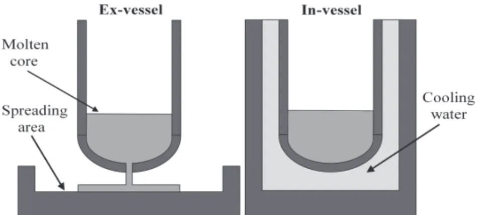
Figure 22.6 Passive containment cooling system of the AP1000. Courtesy of the Westinghouse Electric Company LLC.
removed from the containment vessel by continuous nat-ural circulation of air. During an accident, the air cooling is supplemented by evaporation of water, which drains by gravity from a tank on top of the containment shield build-ing. The positioning of this tank and the central chimney give the reactor building of the AP1000 an outer appearance different from the classical dome shape. In the event of a core melt, the operator can flood the reactor cavity space immediately, surrounding the reactor vessel with water to submerge the reactor vessel; this cooling is sufficient to prevent molten core debris in the lower head from melting the steel vessel wall and spilling into the containment. The CDF of the AP1000 is 3.0×10⁻⁷ events per reactor-year
for initiating events occurring during power operation, and 2.1×10⁻⁷events per reactor-year while shutdown; in both
cases the CDF values include internal events, plus fire and flood [47].
The core of the AP1000 is surrounded by a radial reflector [48]. The average and maximum burnup values for a UO2 core are 53.2 MWd/kgHM and 57.2 MWd/kgHM,
respectively [49]. The AP1000 can also use a 50% Mixed Oxide (MOX, a blend of oxides of plutonium and uranium) core without changes [49]. The expected availability for the AP1000 is better than 93% for an 18-month cycle or alternating 16-/20-month cycles, with 17 days for refueling [46].
The AP1000 has a design lifetime of 60 years based on the service life of the RPV. All other components of the
primary system can be replaced. The target construction time for the AP1000 is 36–48 months, taking advantage of modular construction [50].
The AP1000 was the first Gen III+ design certified by the NRC in December 2005 [51]. It successfully passed all steps of the analysis of compliance with the EUR in June 2006 [39], as well as Step 3 of the Generic Design Assessment in the UK in November 2009 [52], and Phase 1 of the Pre-Project Design Review by the Canadian Nuclear Safety Commission (CNSC) in January 2010 [53]. The construction of the four AP1000 units in China started in 2009 (Sanmen-1 and 2, Haiyang-1 and 2) [54]. As of September 2010, the NRC had received COL requests for the construction of 14 AP1000 units in the United States [55].
The Simplified Pressurized Water Reactor (SPWR) is a Japanese project based on the AP600, with an electric output in the range of 1000–1200 MWe[56]. The European
Passive Plant (EP1000) is a 1000 MWe extrapolation
of the AP600 design with three loops [57], developed by Westinghouse and GENESI (a consortium formed by Ansaldo and Fiat). It successfully passed all steps of the analysis of compliance with the EUR in December 1999 [39].
22.4.3 APR1400
Boveri (Switzerland) and Westinghouse. It is an evolution of the three System 80 reactors built in the Palo Verde plant in the United States (1310 MWe each). The System
80+ was certified by the NRC in May 1997 [58], but
no units were built. However, it provided a basis for the South Korean Optimized Power Reactor OPR1000 and the Advanced Power Reactor APR1400 designs.
The APR1400 is a Gen III two-loop PWR with 4000 MW thermal power and 1390 MWenet electric output
(1450 MWe gross) [59]. The refueling cycle of the core
is 18 months with a maximum discharge burnup of 60 MWd/kgHM [60]. The expected availability is above 90% [61].
The APR1400 is equipped with a combination of active and passive safety measures [62] and an in-vessel corium retention system [63]. The CDF for internal initiating events was estimated at 2.3×10⁻⁶ events per reactor-year, and
for external events it is 4.4×10⁻⁷ events per reactor-year,
including fire- and flood-induced events [64].
The APR1400 was certified by the Korean Institute of Nuclear Energy in 2003. The construction permit for Shin-Kori-3 and 4, which are the first APR1400 plants in Korea, was issued in April 2008; commercial exploitation of these units is expected in 2013–2014 [65]. The planned construction time for the first two APR1400 units is 55 months, to be reduced to 48 months as construction of this series progresses [66]. A Korea Electric Power Corporation (KEPCO)-led consortium won a tender in the United Arab Emirates in early 2010 and will supply four APR-1400 units. The first of the four units is scheduled to begin providing electricity to the grid in 2017, with the three later units being completed by 2020 [65].
22.4.4 APWR
The Advanced Pressurized Water Reactor (APWR) was developed by Mitsubishi (Japan). It is a PWR with 4451 MW thermal output and 1538 MWe gross electric
output [67]. The version proposed for the U.S. market has a gross electric output close to 1700 MWe (approximately
1600 MWe net output) for the same thermal power [68].
The APWR features several design enhancements including a neutron reflector, improved efficiency, and improved safety systems. It uses a combination of passive and active safety systems [69]. The neutron reflector reduces neutron the RPV fast neutron fluence by a factor of three, as compared with a previous four-loop Japanese PWR design (which typically received a fast fluence of about 2×10¹⁹ n/cm2 over 40 years) and improves the reliability
of the vessel [67].
The availability factor of the APWR is expected to be 95%, with a refueling cycle of up to 24 months [67]. The average discharge burnup of the fuel is 49 MWd/kgHM
[70]. The CDF for the APWR is 1.2×10⁻⁶ events per
reactor-year (internal events, all power states) [71]. The construction of the first APWR in Japan (Tsuruga-3) is expected to start in 2012, with commercial operation scheduled for 2017 [72]. The NRC accepted in 2008 the application for design certification of the APWR and, as of September 2010, it received COL requests for the construction of two APWR units in the United States [55]. Mitsubishi is also working on a Gen III+ design, together with Areva. The ATMEA1 is a three-loop PWR, with thermal power of 3150 MW and net electric output of 1100–1150 MWe [73]. The ATMEA1 will be equipped
with three independent emergency core-cooling trains, each with capacity for complete safe shutdown and residual heat removal. The ATMEA1 will also feature an ex-vessel core catcher, similar to the one of the European Pressurized Reactor, described in the next section.
22.4.5 EPR
The European Pressurized Reactor or Evolutionary Pressur-ized Reactor (EPR) is a Gen III+ PWR from Areva. It is an evolution of the French N4 and German Konvoi reactors. It is one if the largest reactors available, with a thermal power of 4300 MW and net electric output of 1600 MWe
(gross 1720 MWe) [74]. The version for the U.S. market
has a slightly higher thermal power of 4590 MW [75]. The EPR has four independent cooling systems, an extra cooling and containment area in the bottom to catch the molten core if a core meltdown should occur, and a containment building that can withstand a direct crash by a large airplane [76]. An availability of 92% over its 60-year lifetime is expected [48]. A refueling cycle of 18 months was taken as reference, with the possibility to increase it up to 24 months. The EPR was designed for UO2 fuel,
but having the capacity to use MOX fuel at 50% [77]. The discharge burnup for UO2 fuel is 45 MWd/kgHM [74].
Redundancy is achieved through four “trains” of pro-tection, with each train able to provide 100% of the safety duty required to enable safe shutdown and post trip cooling. Additional protection comes from the physical segregation of each of the trains, located in separate buildings. This architecture allows maintenance to be done on one of the trains during plant operation, without requiring a shutdown, as there is still three-fold redundancy, thus helping to ensure a high availability [48].
advantage of achieving a spatial separation of the functions to withstand the thermo-mechanical loads during RPV failure and to transfer the melt into a coolable configuration. The spatial separation leads to a simplification of the design of the retention device and preserves the freedom to replace it by an alternative solution if necessary [78].
Figure 22.7 shows a three-dimensional view of the RPV of the EPR, its corium spreading area, and the nearby IRWST.
The CDF for initiating events occurring during all power states is 6.1×10⁻⁷ events per reactor-year [79]. The EPR
successfully passed all steps of the analysis of compliance with the EUR in December 1999 and June 2009 (revision B) [39]. The construction license of the first EPR, in Finland (Olkiluoto-3), was granted in February 2005, while the construction of the second EPR, in France (Flamanville-3), was authorized in 2007 [80]. The EPR passed Step 3 of the Generic Design Assessment in the UK in November 2009 [81]. The application for design certification by the NRC was submitted in late 2007 [82]. Besides the two EPR units under construction in Europe, there are also two more under construction in China (Taishan-1 and 2). As of September 2010, the NRC had received COL requests for the construction of four EPR in the United States [55]. The typical construction time for the EPR in the United States is given as 42 months, from first concrete pouring to fuel loading [75]. The construction of the two EPR units in Europe suffered from initial delays due to problems with concrete placement [83].
22.4.6 IRIS
The International Reactor Innovative and Secure (IRIS) is a medium-sized PWR, developed by an international
Figure 22.7 Location of the corium spreading area (rectangular zone) and in-containment refueling water storage tank relatively to the pressure vessel of the EPR. Courtesy of Teollisuuden Voima Oyj.
Upper head
Pressurizer
Reactor coolant pump (1 of 8)
Steam generator (1 of 8) Control rods deive mechanisms
SG steam out
SG feed-water in Riser
Downcomer
Core
Figure 22.8 The IRIS integral primary system. Reproduced from Carelli and co-authors [86] by permission of Elsevier.
consortium led by Westinghouse. Its thermal output is 1000 MW, for a net electric output of 335 MWe [84].
IRIS has an integral reactor coolant system layout, shown in Figure 22.8.
Vent valve Containment
Reactor pressure vessel
Turbine generator
Gen
Feedwater pump Water
Water
Depressurization valve
Steam generator tube bundle
Steam
Steam
Core
Condenser Feedwater
Figure 22.9 Baseline design concept of the MASLWR. Reproduced from Reyes and co-authors [94] by permission of Elsevier.
downward through the annular downcomer region outside the core to the lower plenum and then back into the core, completing the circuit [85].
The IRIS vessel has an internal diameter of 6.2 m and an overall height of 22.2 m, which makes it approximately 50% larger than the RPV of the AP1000. Nevertheless, the size of the IRIS containment is a fraction of the size of corresponding loop reactors, resulting in a significant reduction in the overall size of the plant [86].
The IRIS “safety-by-design” approach is to eliminate by design the possibility for an accident to occur, rather than dealing with its consequences. If it is not possible to eliminate the accident altogether, then the design should inherently reduce its consequences or decrease its probability of occurrence, without resorting to intervention of active or passive means. The integral configuration of this design eliminates large LOCA altogether, since the usual primary penetrations of the reactor vessel or large loop piping do not exist. The IRIS is equipped with an in-vessel core retention system [87].
The initial fuel loading is designed to provide a four-year cycle utilizing nearly standard PWR fuel with up to 5% enrichment, but with improved fuel utilization, with an average fuel burnup in the 48–53 MWd/kgHM range [86]. The core design parameters are selected so that future UO2and MOX reload cores with higher fissile content (and
longer cycle) are feasible. An eight-year core lifetime is foreseen using UO2 or MOX fuel with a fissile content in
the 7–10% range [88].
The CDF calculated at the conceptual phase of IRIS (internal events only) is 1.2×10⁻⁸events per reactor-year
[89]. The design certification review of the IRIS by the NRC is expected to start in 2012 [90], and Westinghouse anticipates to be able to deploy the reactor by 2015 [86].
22.4.7 NuScale
The NuScale design of NuScale Power Inc. (US) [91] is an integral PWR, based on the Multi-Application Small Light Water Reactor (MASLWR) project developed in the United States by Nexant-Bechtel, the Oregon State University, and the Idaho National Engineering and Environmental Laboratory [92]. The MASLWR has a thermal output of 150 MW and net electric output of 35 MWe. It is a natural
circulation reactor, with the core and helical coil steam generators located in a common vessel.
There is previous experience in the use of natural circulation PWR in the military sector. The reactors powering the Rubis-class submarines of the French Navy, commissioned in the 1980s and 1990s, are based on an integral vessel arrangement and natural circulation is used up to about 30 MW power (about two-thirds of the maximum thermal power). This arrangement is one of the factors that make the Rubis-class submarines smaller than their British or U.S. counterparts [93].
vessel is partially submerged in a water pool that acts as the ultimate heat sink.
The design of the NuScale is modular-based, with the provision of up to 12 modules on the same site. Each containment vessel module containing reactor and steam generator has overall dimensions of 18 m by 4.2 m and will weigh approximately 450 metric tons. The refueling cycle is 24 months long, using fuel enriched at 4.95%. An initial pre-application review meeting was held with the NRC in July 2008, and NuScale anticipates filing the design certification application in 2012 and having the first reactor connected to the grid by 2018 [95].
22.4.8 Other Designs
Babcock & Wilcox (US) is developing the mPower, a modular-based integral PWR, with 125 MWe electric
output and passive safety systems [96]. The mPower is planned for a four-and-a-half-year operating cycle between refueling, using fuel enriched to just below 5%. The reactor will be contained below ground and will have provisions to store the spent fuel underground for the 60 years lifetime of the reactor. Three big U.S. utilities, Tennessee Valley Authority, First Energy Corporation, and Oglethorpe Power Corporation, signed an agreement with Babcock & Wilcox in early 2010, committing to get the new reactor approved for commercial use in the United States.
Other integral PWR in different stages of design are the Central ARgentina de Elementos Modulares (CAREM), with thermal output of 100 MW, under development in Argentina [97], the System-integrated Modular Advanced ReacTor (SMART), with thermal output of 330 MW, under development in Korea [98], and the Integrated Modular water Reactor (IMR), with thermal output of 1000 MW, under development in Japan [99].
22.5 GEN III/III+ BOILING WATER REACTORS
BWR reactors, like PWRS, have their origins in the technology initially developed for the U.S. Navy. BWR is the second most-used design, with 94 units out of a total of 438 units in operation at the end of 2008, providing approximately 23% of the integrated power throughout the world in that year [29]. The reference fuel for BWR is also UO2 in pellet form, enriched to 2–4%, clad in Zircaloy.
A typical fuel assembly consists of an 8×8 array of fuel
rods of about 1.3 cm diameter and 4 m height. The 8×8 array is surrounded by a Zircaloy fuel channel to prevent cross-flow between assemblies. A group of four assemblies constitutes a module, together with a cruciform control rod in the center. The core of a BWR contains typically 750 fuel assemblies with 140,000 to 160,000 kg of UO2. The coolant
typically enters at about 7 MPa, flows downward between
the RPV inner wall and the core shroud, is distributed by the core plate, flows upward through the core and upper structure, and exits as steam at about 290◦C. About 30% of the coolant flow is recirculated, which has the net effect of increasing the coolant flow rate in the core [100]. The control of a BWR is different from the one of a PWR, as the direct cycle links thermal power, pressure, and water level. Thermal power, and hence the steam flow rate, is changed either through the recirculation flow rate or by the position of the control rods. Typically, automatic load following is achieved by changing the recirculation flow above 65% power and by using the control rods below that level.
Dresden-1 was the first large-scale BWR (200 MWe)
developed by General Electric (US), which started operat-ing in 1960. Oyster Creek was the first direct cycle BWR (650 MWe), that started operating in 1969 and was
charac-terized by the elimination of the steam generators and the use of five external recirculation loops. The Dresden-2 plant first featured in 1970 internal jet pumps, which improved recirculation flow so that only two external recirculation loops were needed [101].
22.5.1 ABWR
The Advanced Boiling Water Reactor (ABWR), developed by General Electric (US), Toshiba and Hitachi (Japan) [102], was the first Gen III reactor to enter commercial operation in 1996. A significant feature of the ABWR is the absence of large nozzles below the elevation of the top of the core. The ABWR has 10 internal recirculation pumps inside the RPV, replacing the external pumps of older BWR designs, together with all their piping, valves, and snubbers. The internal pumps are an improved version of a model previously used in European plants [103]. This configuration of the RPV precludes any large pipe ruptures at or below the elevation of the core and is a key factor in the ability of ABWR safety systems to keep the core completely and continuously flooded for the entire spectrum of design basis LOCA. The CDF (internal events) for the ABWR is 1.6×10⁻⁷ events per reactor-year [104], nearly
an order of magnitude lower than General Electric’s BWR/6 older design [105]. The ABWR also features a basaltic floor with passive cooling features that will terminate the flow of corium in the event of a core melt [106]. The thermal power of the Kashiwazaki-Kariwa twin units is 3926 MW, with a net electric output of 1315 MWe [21,
107]. The ABWR availability factor is 87% or greater, with a refueling interval up to 24 months [108].
Four ABWR units are currently in operation in Japan (Kashiwazaki-Kariwa-6 and 7, Hamaoka-5 and Shika-2), two are under construction in Taiwan (Lungmen-1 and 2), and one unit is under construction in Japan (Shimane-3). The average time from start of construction to connection to the grid of the first four ABWR units built in Japan was 44 months, while the average time from start of construction to start of commercial operation was 52 months [21]. The two units in Taiwan, whose construction started in 1999, are expected to start commercial operation in 2011–2012 [110]. The unit in Japan, whose construction started in the end of 2005, is expected to start commercial operation in early 2012 [72]. Two ABWR units are slated to start operation in the United States (South Texas Project) in 2016–2017 [111]. The average energy availability factor of the first two units in Japan, over the first 10 years of operation, was 82%; this value later decreased due to extraordinary inspections after the earthquake in July 2007 [20].
22.5.2 ESBWR
In the late 1980s General Electric began a BWR design project that incorporated advanced, passive safety features. The Simplified Boiling Water Reactor was a natural circulation reactor rated at 600 MWe[112]. This ultimately
evolved into the Gen III+ Economic Simplified Boiling Water Reactor (ESBWR) design, with thermal power of 4500 MW and net electric power of 1535 MWe
(gross 1600 MWe)[113], which took several technological
features from the ABWR already in operation. Significant experience with natural circulation BWR was obtained with the 200 MW Humboldt Bay-3 reactor in the United States [114], operated from 1963 to 1976, and with the 183 MW Dodewaard reactor in the Netherlands [115], operated from 1969 to 1997.
The ESBWR has no recirculation pumps, external or internal, thereby greatly increasing design integrity and reducing overall costs. The passively safe characteristics are mainly based on isolation condensers, which are heat exchangers that take steam from the vessel or the containment, condense it, transfer the heat to a water reservoir, and introduce the water into the vessel again. All safety systems operate without using pumps, thereby further increasing design safety reliability and reducing costs. The core is made shorter than conventional BWR plants to reduce the pressure drop over the fuel and improve natural circulation [116, 117]. The ESBWR is equipped with an ex-vessel core catcher, which uses thick concrete and a passive cooling system to prevent escape of the corium from the containment [118].
The design and operation simplification contribute to a 20% operation and maintenance cost advantage [119]. The expected ESBWR availability factor is 92% or greater, with a refueling interval up to 24-months [117]. General Electric
puts the construction time of the ESBWR at 42 months, using proven ABWR construction techniques [120].
The CDF of the ESBWR is currently the lowest of all Gen III/III+ designs, at 2.8×10⁻⁸ events per reactor-year
for initiating events occurring during power operation and at 3.36×10⁻⁸ events per reactor-year when the plant is
shut down (in both cases, the CDF values include internal events, plus fire and flood) [121].
The design certification review of the ESBWR by the NRC was started in 2005. The NRC issued a final safety evaluation report and final design approval in March 2011. Step 2 of the Generic Design Assessment in the UK was completed during 2008 [118]. As of September 2010, the NRC had received COL requests for the construction of five ESBWR units in the United States [55].
22.5.3 SWR-1000
The Siedewasserreaktor (SWR, “Boiling Water Reac-tor” in German) is a Gen III+ design developed by Siemens/Framatome (Areva) in a joint venture with Ger-man, Finnish, and other European utilities, which started in 1992. The SWR-1000 has a thermal output of 3370 MW and a net electric output of 1250 MWe [122]. The safety
concept of the SWR-1000 is based on a combination of pas-sive safety systems and a reduced number of active safety systems. All postulated accidents can be controlled using passive systems alone. Nevertheless, service-proven active safety systems are still intended to operate, if possible, before passive safety equipment takes over. The functional scope and degree of redundancy of these active systems could, however, be reduced [123].
Figure 22.10 shows a comparison of the RPV of the SWR-1000 with the older design for the Kruemmel plant (1350 MWe, Siemens Product Line 69) built in the late
1970s. The active core height of the SWR-1000 was reduced from 3.7 to 3.0 m, and, as a result, the top of the core is positioned lower inside the RPV. Since the overall height of the RPV remains the same as before and the main steam and feedwater nozzles are positioned at a higher ele-vation on the RPV shell, this arrangement provides a much larger water inventory above the core for accident control purposes. The volume of water above the core is such that, during post-accident reactor depressurization, no active supply of makeup coolant to the RPV is needed to maintain fuel cooling. To increase the effective water inventory even further, a chimney is provided above the core in which the steam-water mixture is routed through pipes.
Steam dryer
Steam separator
Chimney
Reactor core
Kruemmel SWR-1000
95202a
Figure 22.10 Comparison of the pressure vessel of Areva’s SWR-1000 reactor with the one of the Kruemmel reactor. Reproduced from Stosic and co-authors [122] by permission of Elsevier.
flooded using water from the core flooding pools to cool the RPV [124].
The average availability for a plant lifetime of 60 years and 12 months long refueling cycle is 94.5%. The SWR-1000 can have fuel cycles up to 24 months [122].
The CDF of the SWR-1000 is one of the lowest for Gen III/III+ designs, at 4.3×10⁻⁸ events per
reactor-year for initiating events during operation at power, and 4.1×10⁻⁸ events per reactor-year while shutdown [122].
A preliminary safety assessment published by STUK in 2001 confirmed that there were no safety technical obstacles for the SWR-1000 to be approved in Finland [125]. The compliance assessment with the EUR was successfully completed in February 2002 [39]. The process to start the design certification by the NRC was started in 2002 [126].
22.6 GEN III/III+ PRESSURIZED HEAVY WATER REACTORS
In the 1950s and 1960s, heavy water reactor technology was explored in several countries [127]. However, it was
in Canada that this line of reactors was selected as the preferred type, which would become known as CANada Deuterium Uranium (CANDU). At the end of 2008 there were 44 PHWR units in operation worldwide, of Canadian and Indian origin, providing approximately 6% of the integrated power throughout the word in that year [29]. The main attraction for the development of PHWR is the comparative simplicity of a system that does not depend on uranium enrichment. Further simplicity was introduced with the choice of pressure tubes, rather than a pressure vessel, to contain the operating pressure. The use of natural uranium and of pressure tubes makes this technology relatively easily accessible. Fuel manufacture has been successfully developed virtually everywhere where these reactors have been built, and the dependence on very specialized large component fabricators to produce pressure vessels has been avoided [128].
The CANDU series of reactors developed by Atomic Energy of Canada Limited (AECL) is designed to use natural uranium, but it can also use low enriched uranium [129] or a variety of fuels, including fuel discharged from light water reactors [130], and thorium, in combination with uranium or plutonium [131–133]. CANDU reactors are refueled on-power, thus avoiding the need for a refueling outage typical of other designs.
The core of a CANDU reactor is contained in a cylindrical stainless steel tank (calandria) that holds the heavy water moderator at low temperatures (<80◦C) and low pressure (about 0.1 MPa). The ends of the cylinder are closed with two parallel end shields that are perforated with holes for the fuel channels, the holes being arranged in a square lattice pattern. Thin-walled Zircaloy tubes are fastened to each inner tube sheet and act as stays for the end shields to form a leak-tight tank. The holes in each end shield are connected with stainless steel tubes (lattice tubes). Each fuel channel (approximately 400 in total) consists of a pressure tube joined to end fittings and occupies the tubular holes or lattice sites formed by each combined lattice tube and calandria tube. The coolant enters the pressure tube at about 265◦C and exits at about 310◦C. Each fuel channel contains 12 bundles, resulting in a loading of about 100,000 kg of natural UO2 [134].
The calandria is not a reactor vessel and is not subjected to the high pressures that are required in order to circulate liquid reactor coolants; its function is to hold the heavy water moderator and permit its recirculation. A RPV for a heavy water moderated reactor must be very large. Since deuterium in D2O is twice as heavy as hydrogen in H2O,
fast neutrons lose (on average) less energy per collision in D2O and travel greater distances before reaching thermal
energies than in H2O. The core of a D2O-moderated
reactor is thus larger than the one of a H2O-moderated
(started in 1981 but still unfinished). The RPV of Atucha-1
(335 MWe) has a 6.2 m diameter, 12.2 m height, and
weighs 470 metric tons, while the one of Atucha-2
(692 MWe) has an 8.4 m diameter, 14.3 m height, and
weighs 971 metric tons [136].
The use of natural uranium and the initial use of heavy water as both moderator and coolant resulted in a lower operating temperature of the coolant fluid, when compared with a light water reactor, and thus in a slightly smaller efficiency [135].
22.6.1 EC6
AECL has developed a Generation III CANDU design, the Enhanced CANDU 6 (EC6), with 750 MWegross electric
output. The EC6 is a water moderated and heavy-water cooled pressure tube reactor, based on the latest CANDU-6 (Generation II) plants built by AECL in China (Qinshan III-1 and III-2), which were connected to the grid in 2002–2003. The target operating life for the EC6 is 60 years (while that of CANDU6 is 30–40 years), with some critical components being replaced around mid-life.
The EC6 has a projected availability factor of over 90% [137]. The lifetime energy availability factor for all CANDU-6 reactors (11 units in five countries) was 88.1% until the end of 2008 [20]. The expected overall project duration for the EC6 is 66 months, with the possibility of having a second unit in service six months later. The Qinshan III twin CANDU-6 units took 54 and 57 months from start of construction until connection to the grid [21]. The CNSC completed Phase 1 of the Pre-Project Design Review of the EC6 in March 2010 [138].
22.6.2 ACR-1000
AECL also developed a Gen III+ design, the Advanced CANDU Reactor (ACR), which uses low enriched uranium instead of natural uranium as previous models. The use of enriched uranium is expected to result in operational savings [129]. The ACR will have a small negative coolant void coefficient [139], in contrast with the earlier designs, which feature a small positive void coefficient [140].
The coolant of the ACR will be light water instead of heavy water, which will be retained only as moderator. The new design will simplify the complex system of cooling pipes running through a more compact core [141] and will use new alloys for the piping in order to guarantee a lifetime of 60 years [142]. Two versions were developed, the ACR-700 with thermal output of 1980 MW and gross electric output of 731 MWe[143], and the ACR-1000 with
thermal output of 3180 MW and gross electric output of 1165 MWe[139].
The ACR-1000 has a planned lifetime capacity factor greater than 90% [144]. It will have a three-year opera-tional cycle, with 21-day maintenance outage, achieved
through an increase of online maintenance [144]. The fuel enrichment of the reference core is 2.4%, and the average fuel burnup is 20 MWd/kgHM [145], while for a typical CANDU-6 it is 7.5 MWd/kgHM [139]. Even if a typical PWR fuel burnup is three to six times higher than the value for a CANDU-6, this is the result of fuel enrichment, not of a higher fuel efficiency, as the uranium utilization is lower by about 25% in a CANDU-6, due to its neutron economy [146].
Figure 22.11 shows a three-dimensional view of the calandria, steam generators, and main heat transport system of the ACR-1000. The heat transport system with light water coolant is disposed in a two-loop configuration, with four steam generators, four heat transport pumps, four reactor outlet headers and four reactor inlet headers. Figure 22.11 also shows the arrangement of the pipes that connect the fuel channels (at their lower ends) to the headers (at their upper ends) on the two sides of the calandria. This configuration is similar to the one of CANDU-6 reactors. The lattice pitch of the ACR-1000 is 240 mm, while the one of a CANDU-6 is 286 mm. This makes significant differences in the calandria size. The calandria of the ACR has a diameter of 7.5 m, nearly identical to the one of a CANDU-6, but with higher power; in contrast, the one of the ACR-700, which has approximately the same power of the CANDU-6, has a diameter of only 5.2 m.
The CDF of the ACR-700 for internal initiating events during power operation is 3.4×10⁻⁷ events per
reactor-year [147]. The corresponding values for the ACR-1000 are expected to be lower due to design improvements over the ACR-700, such as a four-quadrant configuration, more reliable emergency feed-water system, passive makeup systems, and passive containment cooling. The target CDF value for the ACR-1000 for internal events at power and shutdown, plus fire and flood, is in the range of 8×10⁻⁸−
8×10⁻⁷ events per reactor-year [148].
In October 2004 the NRC concluded a pre-application review of the ACR-700 [80]. The CNSC started a pre-licensing of the ACR-700 in May 2003, which resulted in a report issued in April 2006 [80]. Meanwhile AECL had decided to redirect its efforts to the development of the ACR-1000. The CNSC completed Phase 2 of the Pre-Project Design Review of the ACR-1000 in 2009 and found no barriers to license the reactor [149]. The ACR-1000 design also successfully completed step 2 of the Generic Design Assessment in the UK in 2008 [148]. The first ACR-1000 is expected to be operational in Canada around 2016.
22.7 GEN III/III+ HIGH-TEMPERATURE, GAS-COOLED REACTORS
Figure 22.11 Calandria, steam generators, and main heat transport system of the ACR1000. Reproduced from Pedherney and co-authors [141] by permission of the American Society of Mechanical Engineers.
2008 there were 18 gas-cooled reactors in operation worldwide, corresponding to about 2% of the integrated power throughout the world in that year [29]. HTGRs use helium instead of air or CO2as the coolant, in combination
with a graphite moderator, as this offers enhanced neutronic and thermal efficiencies. It also makes it possible to produce high temperature nuclear heat, and hence the name HTGR [150]. Early HTGR were the Dragon test reactor in the UK (20 MW, 1965), the Peach Bottom-1 in the United States (115 MW, 1967), and the AVR in Germany (49 MW, 1968). These were followed by the Fort St. Vrain plant [151] in the United States (842 MW, 1979) and the THTR plant in Germany (750 MW, 1985). In addition to demonstrating the use of helium coolant (with outlet temperatures as high as 950◦C) and graphite moderator, these plants also demonstrated coated particle fuel, a fuel form that employs ceramic coatings for containment of fission products at high temperature.
HTGR use fuel that is significantly different from that used in current reactors: 1 mm-diameter spheres containing
a kernel of fuel surrounded by three layers of carbon and one layer of silicon carbide (SiC) formed by Chemical Vapor Deposition (CVD), in a design called tri-isotropic (TRISO)-layered particles, developed in Germany within a program started in the 1960s [152].
Figure 22.12 shows a schematic view of a coated fuel particle as well as spherical and block-type fuel elements for HTGR [153]. The spherical fuel elements have a diameter of approximately 60 mm, similar to a tennis ball, while the block-type fuel hexagonal elements are 600–800 mm long by 360 mm across. In the block-type elements, the TRISO-coated particles are mixed with a carbonaceous matrix and formed into cylindrical fuel compacts, approximately 13 mm in diameter and 50 mm long [154].
Outer pyro-carbon – structural strength
SiC – main fission-product barrier
Inner pyro-carbon – retains fission gases
Porous carbon buffer – space for fission gases and CO
Kernel UO2+ UC2(for uranium without oxygen) 1mm
Final fuel forms
Figure 22.12 Schematic of coated fuel particle and fuel elements for high-temperature, gas-cooled reactors. Reproduced from Olander [153] by permission of Elsevier.
22.7.1 GT-MHR
General Atomics (US) and the Experimental Design Bureau of Machine Building (OKBM, Russian Federation) have jointly developed the Gas Turbine Modular Helium Reactor (GT-MHR). The overall goals are to develop the GT-MHR for the disposition of surplus weapons plutonium in Russia and then to offer GT-MHR plants fueled by uranium to the international market for electricity generation [155]. The GT-MHR will use block-type TRISO fuel elements, with the same design as the ones of the Fort St. Vrain demon-stration plant built by General Atomics [151]. The standard fuel block contains about 20 million coated fuel particles; only 0.7 kg of weapons-grade plutonium is loaded per 115 kg mass of graphite fuel block. This design is expected to achieve an average burn-up of 640 MWd/kgHM [155].
The GT-MHR consists of two interconnected units, each inside a pressure vessel: the modular high-temperature reactor and the direct gas turbine cycle power conversion unit. The power conversion unit uses reactor outlet helium in a direct Brayton cycle. It consists of a gas turbine, a recuperator, a pre-cooler, low-pressure and high-pressure compressors, an intercooler, and a generator.
Figure 22.13 shows the layout of the two interconnected pressure vessels in the 1994 design by General Atomics, very close to the current, optimized design [156].
The thermal power of the GT-MHR is expected to be 600 MW, achieving a net efficiency between 46.5% and 47.5% at 850◦C [156]. Other options for the power conversion unit were considered, namely Rankine and
Brayton indirect cycles, but these were abandoned for the higher efficiency of the direct Brayton cycle. Although the GT-MHR could deliver helium at temperatures up to 1000◦C, a temperature of 850◦C was chosen for the current design as a compromise between efficiency and material limitations. Deployment of the GT-MHR is expected by 2021 [157].
22.7.2 PBMR
The Pebble Bed Modular Reactor (PBMR) is being devel-oped by PBMR Pty (South Africa) for the utility Eskom. The founder investors of PBMR Pty are Westinghouse, Eskom, and the Industrial Development Corporation of South Africa Ltd. BNFL (UK) and Exelon (US) partic-ipated in the initial feasibility study. The PBMR reactor core takes the form of a tall annulus, 11 m high with inner and outer diameters of 2 and 3.7 m. This annular space is filled with some 450,000 fuel spheres 60 mm in diameter, each one having 9 g of enriched uranium. The fission heat is removed from the spheres by high-pressure helium driven downwards through the annular fuel bed. Spent fuel spheres are discharged and replaced with new ones while the reactor remains at power. All 450,000 spheres stay in the reactor for approximately three years, during which time they make six passes down through the core. The PBMR can achieve a fuel burnup of 93 MWd/kgHM at discharge [158].
Generator Control rod housings
Core
Shutdown cooling system Turbine
Recuperator
Compressor
Intercooler
Precooler
Figure 22.13 Design of the GT-MHR by General Atomics in 1994. Reproduced from Baxi and co-authors [156] by permission of C.B. Baxi (General Atomics).
and has a inner diameter of 6.2 m, or double the height (and 1.5 times the diameter) of the vessel of the AP1000 [158]. The thermal power of the PBMR was initially planned at 400 MW for a net electric output of 165 MWe, thus
achieving a net efficiency of 41% while operating at 900◦C using a direct Brayton cycle. However, the thermal output was later reduced to 200 MW, the output temperature was reduced from 900◦C to 750◦C, and the design was changed into using a Rankine cycle in order to simplify the plant and expedite its licensing [159]. These changes would bring the net electric output of the PBMR close to 80 MWe. The
lack of experience and knowledge from predecessor plants raised several issues at the start of the licensing procedure in South Africa [160]. It was expected that the first PBMR would be operational in the Koeberg site (near Cape Town), around 2020, but the project was cancelled in late 2010.
22.7.3 Other Designs
The Japan Atomic Energy Research Institute is working on the design of a 600 MW (thermal) reactor, the Gas Turbine High Temperature Reactor (GTHTR), aimed at co-production of hydrogen [161]. This program started with
the construction of the 30 MW (thermal) High Temperature Test Reactor (HTTR), which achieved first criticality in 1998, full power with a reactor outlet coolant temperature of 850◦C in 2001, and full power with outlet coolant temperature of 950◦C in 2004 [162].
Work on a pebble bed concept is also going on in China, which started with a test reactor, the HTR-10, with 10 MW thermal output, that went critical in 2000, and has the goal of achieving a demonstration plant, the HTR-PM, with two 250 MW thermal output units around 2013 [163].
22.8 CONCLUSIONS
in construction and exploitation issues for increased com-petitiveness. Gen III/III+ designs thus positively address the main concerns of the post-Chernobyl era.
Acknowledgments
The author gratefully acknowledges Prof. Donald Olander (Uni-versity of California, Berkeley, US), Dr. Karl Verfondern (Research Center J¨ulich, Germany), Dr. Mario Carelli (Westing-house Electric Company, US) and Dr. Chandrakant Baxi (General Atomics, US) for making available images from their work for reproduction in this review. Teollisuuden Voima Oyj (Finland), the Westinghouse Electric Company, and General Atomics are acknowledged for their authorization to reproduce images. Mr. Jiri Mandula (International Atomic Energy Agency, Austria) is kindly acknowledged for his assistance in obtaining data from the PRIS database.
REFERENCES
1. World Nuclear Association,Safety of Nuclear Power Reac-tors. Information Paper 6, March 2011. http://www.world-nuclear.org/. Accessed March 27, 2011.
2. W. Frisch, and G. Gros, Improving the safety of future nuclear fission power plants. Fusion Engineering and Design, 2001,56–57, 83–93.
3. I. Hore-Lacy, Nuclear Energy in the 21st Century. World Nuclear University Press, London, 2006, pp. 64–68. 4. J.G. Marques, Evolution of nuclear fission reactors: third
generation and beyond, Energy Conversion and Manage-ment, 2010, 51, 1774–1780.
5. World Nuclear Association,Advanced Nuclear Power Reac-tors. Information Paper 8, March 2011. http://www.world-nuclear.org/. Accessed March 27, 2011.
6. International Nuclear Safety Advisory Group,Basic Safety Principles for Nuclear Power Plants, 75-INSAG-3 Rev. 1, STI/PUB/1082. IAEA, Vienna, 1999, 11–12.
7. W.F. Werner, M. Hirano, S. Kondo, G. Johanson, J.M. Lanore, J.A. Murphy, and U. Schmocker, Results and insights from level-1 probabilistic safety assessments for nuclear power plants in France, Germany, Sweden, Switzer-land and the United States.Reliability Engineering and Sys-tem Safety, 1995,48, 165–179.
8. International Atomic Energy Agency, Status of Advanced Light Water Reactor Designs 2004, TECDOC-1391. IAEA, Vienna, 2004.
9. B.R. Sehgal, Stabilization and termination of severe acci-dents in LWRs.Nuclear Engineering and Design, 2006,236, 1941–1952.
10. J.M. Seiler, B. Tourniaire, F. Defoort, and K. Froment, Consequences of material effects on in-vessel retention, Nuclear Engineering and Design, 2007,237, 1752–1758. 11. O. Kym¨al¨ainen, H. Tuomisto, and T.G. Theofanous,
In-vessel retention of corium at the Loviisa plant. Nuclear Engineering and Design, 1997,169, 109–130.
12. L. Ech´avarri, Energy for the 21st Century: The Potential for Nuclear Power. IAEA Scientific Forum at the General Conference 2007. Vienna, Austria, September 2007. 13. Nuclear Energy Institute, Licensing New Nuclear Power
Plants Fact Sheet. NEI, Washington, October 2010. http:// www.nei.org/. Accessed March 27, 2011.
14. E. Bertel and G. Naudet, L’ ´Economie de L’ ´Energie Nucl´eaire, EDP Sciences, Les Ulis, 2004.
15. T.L. Dickson and S.N.M. Malik, An updated probabilistic fracture mechanics methodology for application to pressur-ized thermal shock.International Journal of Pressure Vessels and Piping, 2001,78, 155–163.
16. M.T. Simnad, Nuclear reactor materials and fuels, in Encyclopedia of Physical Science and Technology, Third Edition, R.A. Meyers (Ed.), Academic Press, 2001, pp. 775–815.
17. C. Leitz and, J. Koban, Development of reactor pressure vessel design, neutron fluence calculation, and material specification to Minimize Irradiation Effects, in Radiation Embrittlement of Nuclear Reactor Pressure Vessel Steels -An International Review, ASTM STP 1011, Third Volume, Steele LE (Ed.), American Society for Testing and Materials, Philadelphia, 1989, 130–144.
18. Jendrich U, Tricot N, Neutron Fluence at the Reactor Pressure Vessel Wall— a Comparison of French and German Procedures and Strategies in PWRs, Eurosafe Forum, Berlin, November 2002. http://www.eurosafe-forum.org. Accessed March 27, 2011.
19. Nuclear Energy Agency,Nuclear Power Plant Life Manage-ment and Longer-term Operation, NEA, Paris, 2006. ISBN 92-64-02924-9.
20. International Atomic Energy Agency,Operating Experience with Nuclear Power Stations in Member States in 2008, IAEA, Vienna, 2009, 656–657. ISBN 978-92-0-159909-4. 21. International Atomic Energy Agency,Power Reactor
Infor-mation System (PRIS), http://www.iaea.org/programmes/a2/. Accessed March 27, 2011.
22. M. Watteau, B. Est`eve, R. G¨uldner, R. Hoffman, and A.N.P. Framatome, ANP extended burnup Experience and views on LWR fuels, Proceedings of the World Nuclear Association Annual Symposium, London, 2001. http://www.world-nuclear.org/.
23. Nuclear Energy Agency,Very High Burn-ups in Light Water Reactors, NEA, Paris, 2006.
24. U.S. Department of Energy Research Advisory Commit-tee and the Generation IV International Forum,A Technol-ogy Roadmap for Generation IV Nuclear Energy Systems, GIF-002-00, DOE and GIF, 2002. http://www.gen-4.org. Accessed March 27, 2011.
25. A.M. Weinberg,The First Nuclear Era: The Life and Times of a Technological Fixer. American Institute of Physics, New York, 1994.
![Figure 22.3 shows the worldwide evolution of the median value of the energy availability factor in the last three decades, using values from the PRIS database [21] of the IAEA, compared with the expected value for Gen III/III+ reactors](https://thumb-eu.123doks.com/thumbv2/123dok_br/16423553.727541/5.1080.564.987.831.1152/figure-worldwide-evolution-availability-database-compared-expected-reactors.webp)


![Figure 22.9 Baseline design concept of the MASLWR. Reproduced from Reyes and co-authors [94] by permission of Elsevier.](https://thumb-eu.123doks.com/thumbv2/123dok_br/16423553.727541/12.1080.236.845.118.503/figure-baseline-concept-maslwr-reproduced-authors-permission-elsevier.webp)

