i
Dissertation
Master in Civil Ingeneering - Building Constructions
DESIGN OF WOOD CONNECTIONS WITH DOWEL
TYPE FASTENERS
Luis Enrique Chávez Rubio
ii This page was intetionally left blank
iii
Dissertation
Master in Ingeneering and Building Construcction
DESIGN OF WOOD CONNECTIONS WITH DOWEL
TYPE FASTENERS
Luis Enrique Chávez Rubio
Dissertation developed under the supervision of Doctor Florindo José Mendes Gaspar, professor at the School of Technology and Management of the Polytechnic Institute of Leiria and co-supervision of Master Wilson Santiago Medina Robalino, professor at the Facultad de Ingeniería Civil y Mecánica of the Universidad Técnica de Ambato.
iv This page was intetionally left blank
v My most sincere acknowledgements to Doctor Florindo Gaspar who as a tutor, with his great human qualities, ability, support and knowledge has given me his conditional help to successfully complete this research project.
To Ing. MSc. Santiago Median who has given me his support during the tutoring process and who has always been ready for any question.
To all my friends who gave me all their support and who helped me improve every day. To all my family, especially my parents Enrique and Isabel, and my brother Xavier who were always in all the good or bad situations to support me and give me strength from the moment I left my country to study. Regardless of the distance, they knew how to transmit all the unconditional love and concern they had towards me so that my studies end with success.
vi This page was intetionally left blank
vii Este trabalho tem como objetivo descrever os diferentes tipos de conectores e fixadores que são feitos para o dimensionamento e dimensionamento de conexões em estruturas de madeira. Para qual, uma descrição de cada um deles e suas características principais é feita.
A seguir, é descrito o uso do programa com as planilhas e como usá-lo para inserir as informações e como os resultados são apresentados usando o Eurocódigo 5. Neste explica a seqüência que deve ser seguida e as diferentes seções da planilha para dimensionamento conexões com diferentes conectores do tipo tarugo. Além disso, indica as variáveis envolvidas no dimensionamento, que é utilizado para descrever os diferentes tipos de conexões a serem analisadas.
O trabalho conclui apresentando todos os resultados da capacidade de resistência dos diferentes tipos de conexões através de tabelas de gráficos e porcentagens que ajudam a perceber como diferentes fatores intervêm na resistência da conexão.
Palavras-chave: ligacões, estruturas de madeira, Eurocódigo 5, ligadores tipo cavilha,
viii This page was intetionally left blank
ix This work aims to describe the different types of connectors and fasteners that is made for the design and dimensioning of connections in wooden structures. For which, a description of each of them and their main characteristics is made.
Next, the use of the program with the spreadsheets is described, and how to use it to enter the information and how the results are presented using the Eurocode 5. It explains the sequence that must be followed and the different sections of the spreadsheet for dimensioning connections with different dowel-type connectors. In addition, it indicates the variables involved in the dimensioning, which is used to describe the different types of connections to be analysed.
The work concludes, presenting all the strength capacity results of the different types of connections through graphs and percentages tables that help to perceive how different factors intervene in the resistance of the connection.
Keywords: connections, wooden structures, Eurocode 5, dowel-type fasteners,
x This page was intetionally left blank
xi Acknowledgements ... v Resumo ... vii Abstract ... ix Table of Contents ... xi List of Figures ... xv
List of Tables ... xvii
List of Acronyms ... xix
1. Introduction ... 1
1.1. Background ... 1
1.2. Objectives ... 2
1.3. Structure of Dissertation ... 3
2. Connections in Wooden Structures... 5
2.1. Beam Connectors ... 5
2.1.1. Concealed Connectors ... 5
2.1.2. Not Concealed Connectors ... 6
2.2. Column to Base Connections ... 9
2.3. Dowel Type Connectors ... 10
2.3.1. Nails ... 10
2.3.2. Screws ... 11
2.3.3. Bolts ... 13
2.3.4. Dowels ... 14
3. Design of Wood Connections ... 17
3.1. Embedment Strength ... 18
3.2. Fastener Yield Moment... 19
xii
3.3.1. Friction effects and Axial Withdrawal of the fastener ... 20
3.4. Nailed Connection ... 21
3.5. Screwed Connection ... 22
3.6. Bolted Connections ... 23
3.7. Dowelled Connection... 24
3.7.1. Wooden Dowelled Connection ... 25
3.8. Effective number of fasteners ... 29
3.8.1. Principal factors affecting the connection strength ... 30
3.9. Comparison between the European and the American method ... 32
3.10. Numerical Models in Timber Connections ... 33
3.11. Design for Durability ... 34
3.11.1. Project Phase: ... 34 3.11.2. Manufacturing Phase: ... 37 3.11.3. Maintenance Phase: ... 37 4. Methodology ... 39 4.1. Introduction ... 39 4.2. Excel Spreadsheet ... 39
4.2.1. Spreadsheet for Metal Dowel-Type Fasteners... 41
4.2.2. Spreadsheet for Wooden Dowels ... 44
4.3. Materials and design ... 46
4.3.1. Type of Connection ... 48
4.3.2. Dowel Type Fasteners ... 49
5. Results and Discussion ... 53
5.1. Timber – Timber Connection... 53
5.1.1. Influence of Splice Piece Thickness ... 53
5.1.2. Influence of Fastener Type ... 55
xiii
5.1.4. Screwed Connection ... 58
5.1.5. Bolted Connection ... 61
5.2. Timber – Steel Connection ... 63
5.2.1. Influence of Steel Plate Thickness... 63
5.2.2. Influence of Fastener Type ... 64
5.2.3. Nailed Connection ... 65
5.2.4. Screwed Connection ... 68
5.2.5. Bolted Connection ... 72
5.3. Timber – Central Steel Connection... 75
5.3.1. Influence of Fastener Type ... 75
5.3.2. Dowelled Connection ... 76
5.3.3. Bolted Connection ... 78
5.4. Mortise and Tenon Connection ... 79
5.4.1. Influence of Fastener Type ... 80
5.4.2. Influence of Wooden Dowel Timber Type... 81
6. Conclusions and future developments ... 83
xiv This page was intetionally left blank
xv
Figure 2.1 Concealed beam connectors ... 5
Figure 2.2 Angle brackets (not concealed connectors) ... 6
Figure 2.3 Hanger connectors ... 7
Figure 2.4 Perforated plates ... 7
Figure 2.5 Punched metal plate fastener with teeth... 8
Figure 2.6 a) Split-ring connectors and Shear-plate connectors ... 8
Figure 2.7 Toothed-plate connectors ... 9
Figure 2.8 Adjustable post base ... 9
Figure 2.9 Different types of nails... 10
Figure 2.10 Coach and countersunk screws ... 11
Figure 2.11 Coach screws ... 12
Figure 2.12 Wood – wood coupling ... 12
Figure 2.13 Typical Bolt ... 13
Figure 2.14 Types of Dowels ... 14
Figure 2.15 Wooden dowels of different diameters ... 15
Figure 3.1 Failure modes of timber connections ... 18
Figure 3.2 Schematic diagram showing the embedment strength tests and load-displacement ... 18
Figure 3.3 Fundamentals of the test for the determination of the yield moment on nails ... 19
Figure 3.4 Strength/strain relationships used for dowel connections ... 20
Figure 3.5 Possible failure modes for wood peg joints ... 26
Figure 3.6 Five percent offset method for defining joint "yield limit load" ... 32
Figure 3.7 Various combinations of wood-bearing and fastener-bending yields for (a) two member connections and (b) three member connections ... 33
Figure 3.8 Protection against termites ... 36
Figure 3.9 Orientation of the sheets in the section ... 37
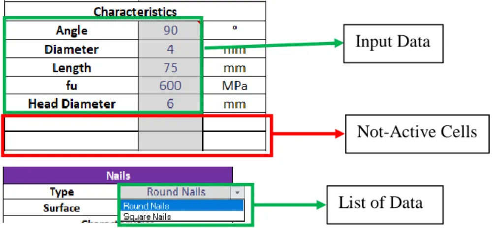
Figure 4.1 Characteristic of input data cells ... 40
Figure 4.2 Characteristics of output data cells ... 40
Figure 4.3 Characteristics of cells output results ... 40
Figure 4.4 Cells of the Geometry Connection ... 41
Figure 4.5 Cells of the Main Timber Member ... 41
Figure 4.6 Cells of Load Characteristics ... 42
Figure 4.7 Cells of Joint Characteristics ... 42
Figure 4.8 Cells of Type of Fastener ... 43
Figure 4.9 Cells Data and Modes of Failure ... 44
Figure 4.10 Cells of Results ... 44
Figure 4.11 Cells of Wooden Dowels ... 45
Figure 4.12 Cells of Mortise and Tenon Connection ... 45
xvi
Figure 4.14 Cells of Results ... 46
Figure 4.15 Detailing of the Connection ... 46
Figure 4.16 Single Shear and Double Shear Connection ... 48
Figure 4.17 Position of the Steel Plate ... 49
Figure 5.1 Timber - Timber Connection – two-splice piece ... 53
Figure 5.2 Influence of splice piece thickness in Timber – Timber Nailed Connection ... 54
Figure 5.3 Influence of type of fastener in Timber - Timber Connection / Splice Piece = 50 mm ... 55
Figure 5.4 Timber - Timber Nailed Connection / Two-Splice Piece = 30 mm ... 56
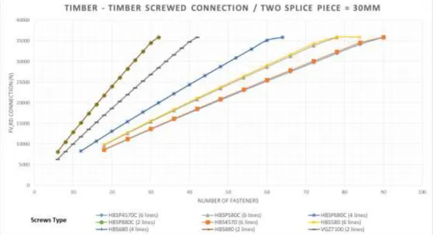
Figure 5.5 Timber – Timber Screwed Connection – Two Splice Piece = 30 mm ... 59
Figure 5.6 Timber – Timber Bolted Connection - Two Splice Piece = 30 mm ... 61
Figure 5.7 Timber – Steel Connection – two-splice piece ... 63
Figure 5.8 Influence of splice piece thickness in Timber – Steel Nailed Connection ... 63
Figure 5.9 Influence of Fastener type on Timber – Steel Nailed Connection – Two Steel Plate = 5 mm .. 64
Figure 5.10 Timber - Steel Nailed Connection - Two Steel Plate = 2 mm ... 65
Figure 5.11 Timber - Steel Nailed Connection- One Steel Plate = 2 mm ... 66
Figure 5.12 Timber - Steel Nailed Connection - Two Steel Plate = 2 mm - Angle 45°... 68
Figure 5.13 Timber - Steel Screwed Connection - Two Steel Plate = 2 mm... 69
Figure 5.14 Timber - Steel Screwed Connection - One Steel Plate = 2 mm ... 70
Figure 5.15 Timber - Steel Bolted Connection / Two Steel Plate = 2 mm ... 72
Figure 5.16 Timber - Steel Bolted Connection / One Steel Plate = 2 mm ... 73
Figure 5.17 Timber - Central Steel Connection ... 75
Figure 5.18 Influence of Fastener Type in a Timber – Central Steel Connection ... 75
Figure 5.19 Timber - Central Steel Dowelled Connection ... 76
Figure 5.20 Timber - Central Steel Bolted Connection ... 78
Figure 5.21 Mortise and Tenon Connection ... 79
Figure 5.22 Influence of Type of Fastener in a Timber – Timber Dowelled Connection (Mortise and Tenon Connection) ... 80
xvii
Table 2.1 Bolts Strength Class according Eurocode 3 ... 14
Table 3.1 Characteristic embedment strengths on Nailed Connections ... 21
Table 3.2 Minimum Detailing Dimension of Pegged Connection ... 26
Table 3.3 Equations for the different failure modes according to NDS ... 27
Table 3.4 Reduction Term, Rd ... 27
Table 3.5 Percentage of Moisture Content according to conditions service ... 35
Table 3.6 Treatment for durability according to the Class of Risk by (EN 350 - 2, 1994) ... 36
Table 4.1 The Main Timber Member Strength Class ... 47
Table 4.2 Service Class by Eurocode 5 ... 47
Table 5.1 Timber - Timber Nailed Connection - Percentage of Strength for a given number of nails ... 57
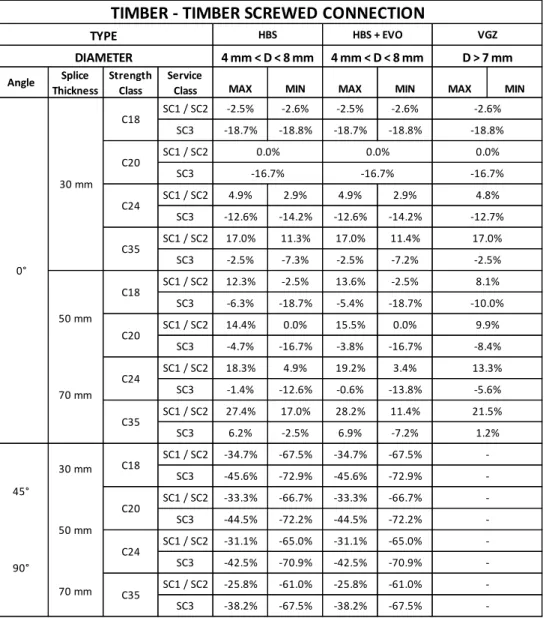
Table 5.2 Timber – Timber Screwed Connection - Percentage of Strength for a given number of screws ... 60
Table 5.3 Timber - Timber Bolted Connection - Percentage of Strength for a given number of bolts ... 62
Table 5.4 Timber - Steel Nailed Connection - Percentages of Strength for a given number of nails ... 67
Table 5.5 Timber - Steel Connection - Percentage of Strength for a given number of screws ... 71
Table 5.6 Timber - Steel Bolted Connection - Percentage of Strength for a given number of bolts ... 74
Table 5.7 Timber – Central Steel Dowelled Connection - Percentage of Strength for a given number of dowels ... 77
Table 5.8 Timber - Central Steel Bolted Connection - Percentage of Strength for a given number of bolts ... 79
Table 5.9 Mortise and Tenon Connection - Percentage of Strength for a given number of wooden dowels ... 82
xviii This page was intetionally left blank
xix
Latin upper case letters
Fax,Rd - Design value of axial withdrawal capacity of the fastener;
Fed - Bearing strength of the peg
Fem - Dowel-bearing strength of the wood;
Fes - Dowel-bearing strength of the wood in the side members Fvp - Effective dowel shear strength;
Fyb - Yield strength of the fastener
Fv,Rd - Design load-carrying capacity per shear plane per fastener;
Gp - Specific gravity for peg;
Gt - Specific gravity for timber member;
My,Rk - Characteristic yield moment of fastener;
Z - Capacity of the connection
Latin lower case letters
fh,i,k - Characteristic embedment strength of timber member i;
ft,0,k - Characteristic tensile strength along the grain;
kmod - Modification factor for duration of load and moisture content;
nef - Effective number of fasteners;
tpen - Penetration depth;
Greek lower case letters
α - Angle between a force and the direction of grain; Angle between the direction of the load and the loaded edge (or end);
xx This page was intetionally left blank
1
1.1. Background
The connections are frequently the critical locations of timber structures, being responsible for the reduction of the continuity and the global structural strength, requiring oversized structural elements. About 80% of failures observed in timber structures are due to connections (Santos, et al., 2009).
The strength and stability of any structure depend heavily on the fastenings that hold its parts together. One main advantage of wood as a structural material is the ease with which wood structural parts can be joined together with a wide variety of fastenings—nails, spikes, screws, bolts, lag screws, drift pins or dowels, staples, and metal connectors of various types (Rammer, 2010).
The present dissertation take into account the Eurocode 5 to design the connections, which considers two types of limit states are considered: ultimate limit states and serviceability limit states. In the Eurocode 5, the safety verification is on base of the partial factor method.
Ultimate limit states are associated with the forms of structural failure where include: loss of equilibrium; failure through excessive deformations, etc.
Serviceability limit states are associated with the adverse effect on the durability of the structure where include: vibrations which cause discomfort to people or damage to the structure, damage (including cracking).
The principles of limit state design take into account the following aspects (EUROCODE 5, 2008):
- Different material properties (e.g. strength and stiffness);
- Different time-dependent behaviour of the materials (duration of load, creep); - Different climatic conditions (temperature, moisture variations);
- Different design situations (stages of construction, change of support conditions). The three main parameters which influence the load-carrying capacity behaviour of joints with dowel-type fasteners are:
Embedding Strength (fh,k) Fastener Yield Moment (My,k) Withdrawal strength (Fax,Rk)
2 In Europe, the design of the connections is the main part of the structure that has been analysed and tested to resist the forces acting as wind, self-weight, and in certain countries the forces generated by the seismic actions. The connections are a fundamental part for the stabilization of the structure against the forces caused by different actions.
The design of the connections leads to opt for several alternatives from what type of connection (Timber - Timber or Timber - Steel), wood material, service class, load duration, and the different types of fasteners for the joint of the elements. Therefore, several factors intervene in the design that its effect on the strength of the connection is generally unknown.
The designer must take among several options for the design of the connection the elements that will be used so that the connection is the most efficient and economical. Having several alternatives can generate a little confusion but having a clear idea about how different factors affects to the connection, it would be most useful way to obtain a pre-dimensioning that is valid and effective.
1.2. Objectives
The main objective of this dissertation is to obtain resistance capacity values of several types of wooden connections using different dowel-type fasteners. These values will give a clear idea to the designer in making a decision for dimensioning a connection, in which several variables that directly or indirectly affect the resistance capacity of the connection will intervene. This analysis entails obtaining results that help the designer make quick and efficient decisions based on how different factors can affect the connection and choose the one that is therefore the most economical and feasible.
For the design of each type of connection to be taken into account, a program was developed using spreadsheets, to obtain results efficiently and quickly. With the use of these results it is intended to obtain illustrative graphs that help designer to understand better how the results will vary depending on the type of fastener and the conditions to which the connection is.
To obtain the results, several aspects must be defined in the dimensioning of the connection, which implies:
Define several types of connections by altering the different variables that enter the dimensioning for different dowel-type fasteners.
Calculate for each type of connection the resistance capacity while the number of fasteners increases.
Perform the dimensioning and calculation of a mortise and connection using wooden dowels for comparison with the other types of connections using dowel-type fasteners.
3 Propose graphs that indicate the calculated values vs. the number of fasteners for the
comparison and analysis of the results.
Determine the percentages of increase or decrease in resistance capacity that will depend on the values obtained from a type of base connection.
1.3. Structure of Dissertation
The present dissertation is developed in six chapters, where the aspects of dimensioning of connections in wooden structures as well as the different fasteners and connections that exist in the market are addressed.
The first chapter addresses the importance that should be taken in the design and dimensioning of the connections in wooden structures, the objectives that will be developed in the dissertation and the organization of it.
The second chapter describes the types of connections that companies offer through their catalogues. It describes the advantages of each one and in what situation it can be used, taking into account the kind of service and the use that will be given to the structure. In addition, the types of dowel-type connectors are presented, detailing each one of them and referring to the most important characteristics; in the same way it is added to what type of situations and connections are relatively more viable and that they add a better behaviour in terms of strength.
The third chapter includes the parameters that are taken into account for the dimensioning and design of the wooden connections mentioned in Eurocode 5. These parameters are briefly detailed but describing the main aspects of each one. Afterwards the different types of connections are presented depending on the type of fastener that will be used; describing in a general way the important aspects in the design of each of them. In addition, it mentions the factors that can affect the resistance capacity of the connection and some research that is developed with finite element programs to encompass all these factors. Finally, durability design is mentioned, an important aspect for the structure and its connections to maintain their capacity throughout their useful life.
In the fourth chapter, a description of the operation of the calculation spreadsheet is made, addressing all the aspects so that the user understands the way in which the program works. It details the sections that must be followed for data entry and how these data generate the necessary information for the design of the connection for both metal
dowel-4 type fasteners and wooden dowels. In addition, the main types of connections to be designed and analysed are described, taking into account all the variables that will intervene in the connection and being able to perform the calculations for the comparison between them. Finally, the characteristics of each type of fastener to be used; being that they exist in catalogues to obtain real values.
In the fifth chapter an analysis is made dividing into four types of connections, where each one of them will use the different types of fasteners. These results are compared through the use of graphs. The number of fasteners used to reach it is analysed through the capacity of resistance. This allows obtaining tables that indicate the percentages that increase or decrease the values of resistance capacity with respect to the base values that are taken from each connection.
In the sixth chapter the conclusions that were obtained from the analysis of the results that were made in this research are exposed, and make some recommendations for future developments.
5 The connections for timber are usually made of steel that take different forms to adapt to the needs of the connection and with differences in shape, thickness and even aspects that include their mechanical properties. In this section, a description is made about several types of these connectors including their main characteristics:
2.1. Beam Connectors
2.1.1.
Concealed Connectors
The concealed connectors have several advantages both aesthetics and strength. This kind of connectors are most used in main-to-secondary joist connection in timber structures. The connection system is not a hinge joint, because the geometry creates an extra bending moment in the shear transfer zone. Consequently, the forces generate additional stress on the elements.
The steel connection is protected and isolated by the surrounding timber. Therefore, there is no change in the mechanical properties or strength reduction..
The concealed connectors (Figure 2.1) can have different forms depending of the design requirements. This type of connectors varies depending of the dimensions of the secondary joist, in width is between 45 mm to 290 mm, and in height between 80 mm to 1200 mm. The characteristic shear strength that can withstand varies between 20 kN to 320 kN. (Rothoblaas, 2015)
a) AluMAXI (with holes) b) DISC
6
2.1.2.
Not Concealed Connectors
There are three kinds of not concealed connectors: angle brackets, hangers, and perforated plates.
Angle Brackets
This type of connectors guarantee high stiffness because their geometry and height flexural capacity. The fasteners used are screws, nails or bolts. The slotted holes are discreet in the fixed zone. The field of use are timber-to-timber joints, timber to OSB panels, steel to timber joints, and timber to concrete joints. (Rothoblaas, 2015)
Their dimensions varies in the width between 20 mm to 100mm, in the height between 40mm to 200 mm. The angle of the plate can variety of 90° and 135° (Figure 2.2). The characteristic shear strength varies between 11 kN to 22 kN.
Figure 2.2 Angle brackets (not concealed connectors) (Rothoblaas, 2015)
Hangers
The hanger connectors provide joist support combined with ease installation that are adjusted to suit height of joist. There are specific hangers for supporting trussed rafters and composite timbers from timber members or attached girders to wall plates to provide wind resistant. The advantage is the extra strength due to the speed prongs and the fasteners for these connectors are screws, nails or bolts.
Their dimensions varies in the width between 32 mm to 200 mm, in the height between 100 mm to 436 mm. The characteristic shear strength varies between 2 kN to 21 kN. The
7 Figure 2.3 shows some connectors that can be found in the market. (Simpson Strong-Tie Company Inc., 2004)
a) Adjustable truss hangers b) Adjustable hanger c) Speed prong joist
Figure 2.3 Hanger connectors (Simpson Strong-Tie Company Inc., 2004)
Perforated plates
The perforated plates are designed for solving particular situation where requiring the transfer of tensile forces between timber elements such as beams, structural panels and cladding. (Rothoblaas, 2015)
The Figure 2.4 shows some applications on wooden structures. Their dimensions varies in the width between 40 mm to 400 mm, in the height between 120 mm to 1200 mm. The characteristic shear strength varies between 1.5 kN to 178 kN.
8
Punched metal plate fasteners
A ‘punched metal plate’ (Figure 2.5) is defined as a fastener made of metal plate, having integral projections punched out in one direction and bent perpendicular to the base of the plate, being used to joint two or more pieces of timber of the same thickness, in the same plane. They are generally manufactured from pre-galvanised mild steel strip or stainless steel strips, with thickness ranging from 0.9 to 2.5 mm (TRADA, 2012)
Figure 2.5 Punched metal plate fastener with teeth (TRADA, 2012)
Split-ring and Shear- plate connectors
Split-ring and shear-plate connectors (Figure 2.6) consist of one split-ring/shear-plate with a bolt, washers and nut, and the ring parallel or bevel sided form. The shear-plate joints are used in laterally loaded timber-to-timber connections as well as steel-to-timber connections, in the meantime the split-ring joints only in timber-to-timber connections. They are circular, with diameters from 60 mm to 280 mm. (TRADA, 2012)
a) Split- ring connectors b) Shear-plate connectors
9
Toothed-plate connectors
Toothed-plate connectors (Figure 2.7) are made from cold rolled band steel or hot dipped galvanised mild steel. They are available in a variety of shapes and sizes, with diameters ranging from 38 mm to 165 mm. The larger connectors are available for use in glued-laminated members. They are mostly circulars, but square and oval shapes are also available. The load in a double-sided toothed-plate connector joint is transferred from one timber member to the other through embedding stresses. (TRADA, 2012)
Figure 2.7 Toothed-plate connectors (TRADA, 2012)
2.2. Column to Base Connections
The column to base connections are post bases that provide an adequate distance from the ground for eliminating the risk of wood deterioration due to water splashes and stagnation with adjustable height. The joint transfer compression, tension and base shear depending on the type of base. (Rothoblaas, 2015)
Their dimensions varies in the width between 100 mm to 200 mm, in the height between 130 mm to 250 mm. The characteristic shear strength varies between 48 kN to 220 kN. The Figure 2.8 shows different types that were found in the market:
10
2.3. Dowel Type Connectors
2.3.1.
Nails
Nails are the most widely used dowel-type fasteners. They are used for many forms of structural timber components, such as timber frame stud walls and floor diaphragms, as well as for connecting timber or wood-based panel products together, and for connecting metal plates to timber. The use of nails in large numbers, such as in nail plates, spreads the load more evenly and for this reason has an advantage over bolts (TRADA, 2012). Nails are usually made of steel but can also be made of stainless steel, iron, copper, aluminium, or bronze. The pointed end of a nail is called the point, the shaft is called the shank, and the flattened part is called the head.
There are many different types of nails, the types depending on the material that they are driven into and the degree of holding power that they must have. Two basic classes of nails are common nails and finishing nails (Figure 2.9).
Figure 2.9 Different types of nails (Encyclopædia Britannica, 2008)
The common nail has a large, flat head that is driven in so that it is flush with the material’s surface. A finishing nail has a smaller, narrower head that is driven in below the material’s surface with a special tool called a nail set, or punch; the small depression remaining is filled in with putty. (Encyclopædia Britannica, 2008)
Many Simpson Strong-Tie® products are designed to use common nails, readily available to builders. Certain applications require special fasteners, such as those with length limitations or for use in hostile environments. The diameters are around of 3.75 mm – 4mm with smooth shank or square twist shank (Simpson Strong-Tie Company Inc., 2004).
11
2.3.2.
Screws
For plain timber-to-timber joints, wood screws can be used. The metal screws are often used for steel-to-timber and panel-to-timber joints. As with nails, there are a number of different types of screws available. The most common types are countersunk, head screw, round head screw and coach screw. The screws can be used for fixing joist hangers and framing anchors. (TRADA, 2012).
Wood Screws: These have a coarser pitch (Figure 2.10) than sheet metal or machine screws, and often have an unthreaded shank. The thread-less shank allows the top piece of wood to be pulled flush against the under piece without getting caught on the threads. Sheet Metal Screws: Usually threaded all the way to their head, these will work in wood, but wood screws should not be used in metal (this is based on hardware store employee advice, not experimental evidence). Most of these screws are self-tapping in that they only require a pre-drilled hole (pre-drill sizes).
Coach screws: are suitable for large connections and are also capable of replacing bolts for single-sided access (single shear). The thread is turned down from the original rod diameter (Figure 2.10), leaving a full diameter shank and the screws have hexagonal heads, like bolts. They are used in engineered timber structures, particularly for fastening metalwork to timber. Coach screws require a washer and must always be inserted into a pre-drilled hole.
Figure 2.10 Coach and countersunk screws (TRADA, 2012)
Apart from the screws mentioned above there are many screws designed for specific purposes – for example the self-tapping Assy screw is intended for high strength and the Topix CC screw (Figure 2.11) is intended for joining together large timbers into a tightfitting joint.
12
a) Assy Screw b) Topix CC
Figure 2.11 Coach screws (TRADA, 2012)
In order to gain the maximum load-carrying capacity, screws should be inserted by turning and not by driving with a hammer. Most industrial screws no longer have their traditional slotted head and proprietary head recesses allow screws to be machine driven (TRADA, 2012).
The Rothoblaas catalogue shows different types of screws for each need in the construction:
Carpentry: used timber-to-timber connection also can be used with steel plates and hooks is the type HBS. Screws with diameters between 3.0 and 5.0 mm and a length of less than or equal to 50 mm are provided with an unnotched self-perforating tip that increases the grip and hold of the screws. Ideal for using with single bits, it is easily interchanged in the bit holder to obtain the utmost screwing precision.
Screws with diameters greater than 6.0 mm have a notched self-perforating tip that avoids the risk of the wood splitting. Ideal for use with double bits directly attached to the mandrel to obtain maximum screwing force and stability.
One example is HBS + evo, ideal for use on steel plates with circular holes and hence for exterior fastening systems in service class three (pillar bases). The dimension from 4.5 mm – 8 mm of diameter and length until 200 mm.
Structures: These types of connectors distributes the stress along the entire threaded surface. High resistance connected to the wood cylinder affected by tangential stresses. The result is fewer connectors and less deformation (Figure 2.12).
13 The total thread distributes the perpendicular tensile stress to the fibres along the height of the beam, guaranteeing reinforcement. One example, is the VGZ that has a high resistance steel (fy,k = 1000 N/mm2) with cylindrical head and the diameter vary between 7 mm to 9 mm.
Screws for outdoor: these types of screws have a specific application according to the wood species and the environment conditions. There are a complete array of screws that indicate for which conditions works.
The Rothoblass catalogue shows different fasteners that allow to use for the different corrosion class environmental (C1 – C5). One example, is the screw KKT A4 can be used for all corrosion class and the diameter vary between 5 mm to 9 mm and their length between 20 mm to 120 mm.
2.3.3.
Bolts
Bolts are mostly used for lateral connections in glue-laminated or heavy timber construction. They transmit forces through single shear (two members) or double shear (three members) connections.
Bolts are manufactured in a variety of types based on the configuration of the bolt head. The most common types are the hexagonal head, square head, dome head, and flat head (Figure 2.14).
The standard hex or square heads are used when the bolt head is in contact with wood or steel. More specialized bolts such as the dome head and flat head provide an increased head diameter and are used when the bolt head is in wood contact (Soltis & Wilkinson, 1996).
14 The diameter bolts vary between 4 mm to 30 mm with length between 100 mm to 600 mm. The external diameter of washer is between 16 mm to 105 mm and the internal diameter is between 8 mm to 27 mm. The bolts strength classes according to Eurocode 3 are indicated in the Table 2.1.
Table 2.1 Bolts Strength Class according Eurocode 3
Class 4.6 5.6 6.5 6.8 8.8 10.9
fy (MPa) 240 300 300 480 640 900
fu (MPa) 400 500 600 600 800 1000
2.3.4.
Dowels
Dowels are plain or ribbed rods usually circular in cross section but sometimes deformed in rectangular cross sections as well. Usually dowels have a smooth surface but are also often fluted to ease insertion. Their plain ends are neater in appearance than bolts and are also stiffer.
The dowel ends can be plugged which improves both the appearance and the fire performance. Some common dowel pins are shown in Figure 2.14 (Bickford & Nassar, 1998)
Straight (solid) dowel pin Grooved dowel pin
Vented dowel pin Drilled and tapped dowel pin with vent
Figure 2.14 Types of Dowels (Bickford & Nassar, 1998)
The Rothoblass catalogue indicates the different dowel dimensions that are offered in the market. The diameter vary between 8 mm to 12 mm with a strength class S235 (fy = 235
15 MPa, fu = 360 MPa ) and between 16 mm to 20 mm with strength class of S355 (fy = 355 MPa, fu = 460 MPa). The length vary between 60 mm to 150 mm.
Wooden Dowels
The wooden dowels (Figure 2.15) are called wood pegs and the joints used where they works well are mortise and tenon connections. They are easy to fabricate, efficient frame assembly, and effective in transferring shear forces.
They are fabricated of different materials of wood but is necessary that the timber is a structural wood. The diameter vary between 6 mm to 60 mm and lengths between 350 mm to 1000 mm, depending of wood type. The several types of wood that were tested and the investigations confirm the use in the mortise and tenon connections are the following:
Douglas Fir
Eastern White Pine Red & White Oak Southern Yellow Pine Yellow Poplar
16 This page was intetionally left blank
17 Dowel type connections is a generic term covering nails, screws, dowels and bolts transferring load perpendicular to their longitudinal axis. The design of dowel type connections consists of two relatively independent types of design criteria, a local set and a global set:
The local design criteria consists of plasticity theory applied to the single connector, i.e. the capacity of the connector and of the wood in which it is embedded is evaluated.
The global design criteria consists of criteria for spacing and distance between the single connectors, which are to insure global capacity of the cross section enough to withstand the forces transferred by the connectors. (Pedersen, 2002).
The local design criteria corresponds to the so called European Yield Model formulated by K. W. Johansen. These design criteria for the single connector now form the basis for the design rules given in the Eurocode 5 (EC5-1 1995).
The three main parameters mentioned in the section 1.1 are used to calculate the “Lateral load-carrying capacity” of metal dowel-type fastener taking the local design criteria. The Johansen’s Theory involves the localized crushing of wood, eventually combined with formation of plastic hinges on connector.
There are different failure modes depending of the connection type. This could be timber-timber/timber-wood based connection and timber-steel connection. The failure modes are divided in two groups by single shear and double shear.
Each failure mode has an equation and the minimum value is taken for the verification of the strength of the fastener. In case of timber-steel connection there is one more important thing taking account is the thickness of the steel plate that could be “thin” or “thick” comparing with the diameter of the connector (EUROCODE 5, 2008). The Figure 3.1 shows the different failure modes.
18 Timber-timber/timber-wood based Timber-steel connection
Figure 3.1 Failure modes of timber connections (EUROCODE 5, 2008)
3.1. Embedment Strength
The embedment strength of timber is one of the principal parameter to calculate the design strength capacity of dowel type fasteners when using the European Yield Model (EYM) (Hettiarachchi & Nawagamuwa, 2005)
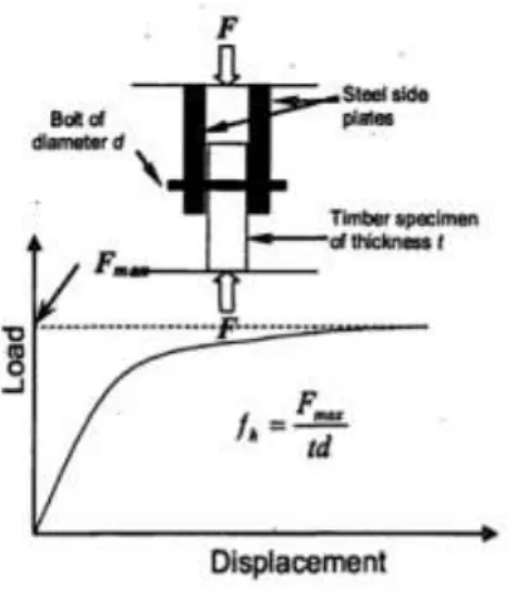
The embedment strength of timber is defined in (EN 383, 1993), fh,k, is the average compressive strength at maximum load under the action of a stiff straight dowel. Taking into account the dowel, is the fictional tension that leads to the crushing of wood. (Figure 3.2)
Figure 3.2 Schematic diagram showing the embedment strength tests and load-displacement (Hettiarachchi & Nawagamuwa, 2005)
19 The most important parameters when considering the embedding are:
Density;
Diameter (fastener and hole);
Angle (between load and grain direction);
Friction (between dowel and timber connection); Moisture.
3.2. Fastener Yield Moment
The yield moment was taken to be the moment at the elastic limit of the fastener and was derived from the product of the yield strength and the elastic modulus of the fastener (Porteous & Kermani, 2007).
The bending capacity (fastener yield moment) is given by the moment value which the complete plasticization of the connector section is reached. Your calculation can be experimental with tests according to normative EN 409:”Timber structures – Test methods – Determination of yield moment for dowel type fasteners – Nails” (EN 409, 1993). These tests (Figure 3.3) are based on the application of an increasing bending moment, until it reaches its maximum value or if there is a 45º angle between the two halves of the nail.
Figure 3.3 Fundamentals of the test for the determination of the yield moment on nails (EN 409, 1993)
3.3. Johansen Equations
The theory used in EC5 is based on Johansen’s (1949) theory. The equation predicts the ultimate strength of a single dowel-type fastener due to either a bearing failure of the joint members or the simultaneous development of a bearing failure of the joint member and plastic hinge formation in the fastener (Debarbouille, 2011)
The ductile failure that Johansen’s theory applies said that the materials of the connection (fastener, timber or wood-based material) would behave as rigid plastic materials according to strength-displacement relationships shown in Figure 3.4.
20
Figure 3.4 Strength/strain relationships used for dowel connections (Porteous & Kermani, 2007)
The behaviour of the connection formed with two pieces where the fastener is subjected to one plane of shear (single shear) is very different of a connection formed by three pieces, where the fastener is subjected to two plane of shear (double shear) (Branco, 2003) The difference between these two types of connections led to the consideration and individualization of each type of rupture analytically through considerations of equilibrium of efforts.
3.3.1.
Friction effects and Axial Withdrawal of
the fastener
In EC5 the Johansen yield equations have been modified to include for friction and withdrawal effects. There are two types of friction effects that can arise in a connection. One will develop if the members are in contact on assembly and the other will arise when the fasteners yield and pull the members together when the fasteners deform under lateral load (Porteous & Kermani, 2007).
In EC5 the values used for the second friction type the factor is 5% where the fastener partially yields (e.g. modes (d) and (e) in Figure 3.1) and 15% where the fastener fully yields (e.g. mode (f) in Figure 3.1).
Fv,Rk = friction factor × Johansen yield load + (withdrawal capacity/4)
To discriminate between the Johansen yield load and the combined withdrawal and friction forces in a connection, the latter are commonly referred to as the rope effect forces, however in EC5 reference is only made to the term Fax,Rk/4 as the contribution from this effect. (Porteous & Kermani, 2007)
The effect of the withdrawal capacity possible to include in the total capacity of the connection is depending on the type of fastener (Debarbouille, 2011). The contribution to the load-carrying capacity due to the rope effect should be limited to following percentages of the Johansen part:
Round nails 15 % Square nails 25 % Other nails 50 % Screws 100%
21 Bolts 25 %
Dowels 0 %
Fax,Rk will be the lower of the fastener head pull-through strength (including the withdrawal strength associated with the headside penetration of the fastener).
3.4. Nailed Connection
Nails are well suited for panel-to-timber and timber-to-timber shear connections. Nails are generally designed for single shear connections.
There should always be at least two nails in a connection. Nails and glue do not have a co-operative action. Unless otherwise specified, nails should be driven in at right angles to the grain.
For square and grooved nails, the nail diameter (d) should be taken as the side dimension. Smooth nails in end grain should not be considered capable of transmitting lateral forces. (METSÄ WOOD, 2018)
The Eurocode 5 indicates for smooth nails produced from wire with a minimum tensile strength of 600 N/mm2, the following characteristic values for yield moment should be used:
𝑀𝑦,𝑅𝑘= {
0.3 ∗ 𝑓𝑢 ∗ 𝑑2.6 𝑓𝑜𝑟 𝑟𝑜𝑢𝑛𝑑 𝑛𝑎𝑖𝑙𝑠
0.45 ∗ 𝑓𝑢 ∗ 𝑑2.6 𝑓𝑜𝑟 𝑠𝑞𝑎𝑢𝑟𝑒 𝑎𝑛𝑑 𝑔𝑟𝑜𝑜𝑣𝑒𝑑 𝑛𝑎𝑖𝑙𝑠} Where:
My,Rk = is the characteristic yield moment, in N.mm;
fu = is the tensile strength of the wire, in mm; d = is the nail diameter, in N/mm2.
For nails with diameters up to 8 mm, the following characteristic embedment strengths apply:
Table 3.1 Characteristic embedment strengths on Nailed Connections
Timber and LVL Plywood
-Without predrilled 𝑓ℎ,𝑘= 0.082 ∗ 𝑝𝑘 ∗ 𝑑−0.3
-With predrilled
𝑓ℎ,𝑘= 0.082 ∗ (1 − 0.01 ∗ 𝑑) ∗ 𝑝𝑘
22
Hardboard Particleborad and OSB
𝑓ℎ,𝑘 = 30 ∗ 𝑑−0.3∗ 𝑡0.6 𝑓ℎ,𝑘= 65 ∗ 𝑑−0.7∗ 𝑡0.1
Where:
fh,k = is the characteristic embedment strength, in N/mm2;
pk = is the characteristic timber density, in Kg/m3;
d = is the nail diameter, in mm; t = is the panel thickness, in mm.
3.5. Screwed Connection
Timber screws are well suited for steel-to-timber and panel-to-timber connections but they can also be used for timber-to-timber connections. Screw connections are generally designed for single shear connections. Screws are good at transmitting axial loads (METSÄ WOOD, 2018).
Eurocode 5 (2008), states that the effect of the threaded part of the screw shall be taken into account in determining the load-carrying capacity, by using an effective diameter (def).
For smooth shank screws, where the outer thread diameter is equal to the shank diameter, the rules given in section 8.2 of Eurocode 5 apply, provided that:
- The effective diameter (def) is taken as the smooth shank diameter;
- The smooth shank penetrates into the member containing the point of the screw by not less than 4d.
Where the conditions above are not satisfied, the screw load-carrying capacity should be calculated using an effective diameter (def) taken as 1.1 times the thread root diameter. For smooth shank screws with a diameter d > 6 mm, the rules in bolted connection apply but for smooth shank screws with a diameter of 6 mm or less, the rules of nailed connection apply.
For the verification of strength of axially loaded screws, the following failure modes shall be taken into account:
23 - the withdrawal failure of the threaded part of the screw;
- the tear-off failure of the screw head of screws used in combination with steel plates, the tear-off resistance of the screw head should be greater than the tensile strength of the screw;
- the pull-through failure of the screw head; - the tensile failure of the screw;
- the buckling failure of the screw when loaded in compression;
- failure along the circumference of a group of screws used in conjunction with steel plates (block shear or plug shear).
3.6. Bolted Connections
Bolts should be tightened so that the members fit closely, and they should be re-tightened if necessary when the timber has reached equilibrium moisture content. If re-tightening cannot be done, and there is a possibility that the timber can dry by over 5 % of its weight after installation of the bolts, only 80 % of the calculated capacity of the bolt connection can be utilized.
Washers with a side length or an external diameter of at least 3d (where d is the diameter of the bolt) and a thickness of at least 0.3d should be used under the head of bolts and nuts. Washers should have a full bearing area.
Bolt holes in timber should have a diameter no more than 1 mm larger than the bolt. Bolt holes in steel plates should have a diameter no more than 2 mm or 1.1d (whichever is greater). If the connection is designed using thick steel plate (t ≥ d) equations and bolt diameter d < 20 mm, the maximum allowed hole in the steel plate should not be more than 1.1d. (METSÄ WOOD, 2018)
For bolts the following characteristic value for the yield moment should be used: 𝑀𝑦,𝑅𝑘 = 0.3 ∗ 𝑓𝑢 ∗ 𝑑2.6
Where:
d = is the bolt diameter, in mm; fu = is the tensile strength, in N/mm2
For bolts up to 30 mm diameter, the following characteristic embedment strength values in timber and LVL should be used, at an angle α to the grain:
𝑓ℎ,𝑎,𝑘 =
𝑓ℎ,0,𝑘
𝑘90∗ 𝑠𝑖𝑛2𝑎 + 𝑐𝑜𝑠2𝑎
24 Where: 𝑘90{ 1.35 + 0.015 ∗ 𝑑 𝑓𝑜𝑟 𝑠𝑜𝑓𝑡𝑤𝑜𝑜𝑑𝑠 1.30 + 0.015 ∗ 𝑑 𝑓𝑜𝑟 𝐿𝑉𝐿 0.90 + 0.015 ∗ 𝑑 𝑓𝑜𝑟 ℎ𝑎𝑟𝑑𝑤𝑜𝑜𝑑𝑠 }
fh,0,k = is the characteristic embedment strength parallel to the grain, in N/mm2;
pk = is the characteristic timber density, in kg/m3; a = is the angle of the load to the grain;
d = is the bolt diameter, in mm.
When is used in timber-wood based connections the following characteristic embedment strength values change:
Plywood Particleboard and OSB
𝑓ℎ,0,𝑘= 0.11 ∗ (1 − 0.01 ∗ 𝑑) ∗ 𝑝𝑘 𝑓ℎ,0,𝑘 = 50 ∗ 𝑑−0.6∗ 𝑡0.2
The axial load-bearing capacity and withdrawal capacity of a bolt should be taken as the lower value of:
- The bolt tensile capacity;
- The load-bearing capacity of either the washer or (for steel-to-timber connections) the steel plate;
- The bearing capacity of a washer should be calculated assuming a characteristic compressive strength on the contact area of 3*fc,90,k;
- The bearing capacity per bolt of a steel plate should not exceed that of a circular washer.
3.7. Dowelled Connection
The dowel diameter (d) should be greater than 6 mm and less than 30 mm. Dowel holes (D) in timber members should have a diameter of 0.95d ≤ D ≤ d. (METSÄ WOOD, 2018) The end of the dowel can be bevelled to make installation easier. The bevel is usually 2 mm. Dowel holes in steel plates should have a diameter no more than 1 mm or 1.1d (whichever is greater)
25
3.7.1.
Wooden Dowelled Connection
Design for transfer of shear forces can be done using one of two international codes, the National Design Specification for Wood connection (NDS) and the Eurocode 5 but in the Europe normative does not specific the pegged connections.
Some investigations get the necessary equations based on the Johansen theory for calculating the shear forces. In some cases, during a frame erection or to resist wind loads, the mortise and tenon joints suffer tension loads.
NDS for Wood Construction (National Design Specification)
Joint Strength
Schmidt (2006), considers an adjustment to the yield model approach. First, the dowel bearing strength of the timber accounts the fact that load is transferred through a wood peg rather than steel dowel, the result is likely a decrease in the values of Fes y Fem (dowel
bearing strengths). Second, the value Fyb needs to describe the flexure yield strength of
the wood peg. Third, an additional yield mode must be considered. Dowel Bearing Strength
Dowel bearing strength depends of the combined deformation of the peg and the timber. There are two approaches to determine the Fes for a peg bearing in the mortise side wall
and Fem a peg bearing in the tenon.
Yield Strength in Bending of a Peg
Dowel bending yield strength Fyb for wood pegs may be taken as the value of modulus of
rupture at 12% moisture content contained in the Wood Handbook. (Forest Products Lab, 1999)
Peg Shear Strength
Mode V is a new yield mode for representing a common failure observed in mortise and tenon joints. The allowable working-level shear stress Fvp in a wood peg is given by:
𝐹𝑣𝑝 = 1365 ∗ 𝐺𝑝0.926∗ 𝐺 𝑡0.778
Where:
Fvp = effective dowel shear strength (psi)
Gp = specific gravity for peg
Gt = specific gravity for timber
26 The corresponding mode V allowable load is:
𝑍 = 𝜋 ∗ 𝐷
2
2 ∗ 𝐹𝑣𝑝 Where:
D = peg diameter that passes through two shear planes in the joint Detailing Requirements
Specifications of end distance (le), edge distance (lv) and spacing (ls) of pegs in a mortise and tenon connection is critical to prevent brittle failure under tension load. Detailing dimension in Table 3.2 have been shown to achieve the full strength of a pegged connection.
Table 3.2 Minimum Detailing Dimension of Pegged Connection (Schmidt, 2006)
Timber Species End Distance
(le) Edge Distance (lv) Spacing (ls) Joint Detaling Douglas Fir 2D 2.5D 2.5D Eastern White Pine 4D 4D 3D
Red & White
Oak 3D 2D 2.5D
Southern Yellow
Pine 2D 2D 3D
Yellow Popular 2.5D 2.5D 3D
In the NDS exist different failure modes similar to the failure modes according to the Johansen’s theory. According to the yield model, double shear connection will fail by one of five possible modes shown in Figure 3.5.
27 A mode Im and mode Is failure are bearing-dominated yield of the main member wood
fibres that are in contact with the fastener. A mode IIIs failure is characterized by fastener
yield in bending at one plastic hinge point per shear plane. A mode IV results from the formation of two plastic hinges per shear plane, but is not considered cause is not observed in practice or in laboratory. A mode Id occurs if the dowel-bearing strength of the members is greater than that of the peg itself. A mode Vd is a cross-grains shear failure
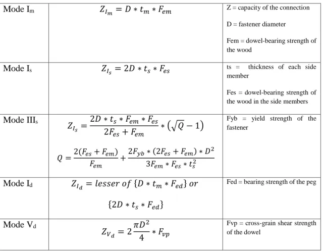
of the peg. The Table 3.3 shows the different equations that use NDS in the failure modes to calculate the capacity of the connection. (Sandberg, et al., 2000)
Table 3.3 Equations for the different failure modes according to NDS
Mode Im 𝑍𝐼𝑚 = 𝐷 ∗ 𝑡𝑚∗ 𝐹𝑒𝑚 Z = capacity of the connection
D = fastener diameter
Fem = dowel-bearing strength of the wood
Mode Is 𝑍𝐼𝑠 = 2𝐷 ∗ 𝑡𝑠∗ 𝐹𝑒𝑠 ts = thickness of each side
member
Fes = dowel-bearing strength of the wood in the side members Mode IIIs 𝑍𝐼𝑠 =2𝐷 ∗ 𝑡𝑠 ∗ 𝐹𝑒𝑚∗ 𝐹𝑒𝑠 2𝐹𝑒𝑠+ 𝐹𝑒𝑚 ∗ (√𝑄 − 1) 𝑄 =2(𝐹𝑒𝑠+ 𝐹𝑒𝑚) 𝐹𝑒𝑚 +2𝐹𝑦𝑏∗ (2𝐹𝑒𝑠+ 𝐹𝑒𝑚) ∗ 𝐷 2 3𝐹𝑒𝑚∗ 𝐹𝑒𝑠∗ 𝑡𝑠2
Fyb = yield strength of the fastener
Mode Id 𝑍𝐼𝑑 = 𝑙𝑒𝑠𝑠𝑒𝑟 𝑜𝑓 {𝐷 ∗ 𝑡𝑚∗ 𝐹𝑒𝑑} 𝑜𝑟
{2𝐷 ∗ 𝑡𝑠∗ 𝐹𝑒𝑑}
Fed = bearing strength of the peg
Mode Vd
𝑍𝑉𝑑 = 2
𝜋𝐷2
4 ∗ 𝐹𝑣𝑝
Fvp = cross-grain shear strength of the dowel
The NDS Code use a reduction factor (Rd) to calibrate yield capacity to allowable capacity. This factor is divided for the different failure modes.
The reduction factor depends of the angle (θ) between the direction of the load and the direction of the grain. The table 3.4 indicate the reduction factor for each failure mode.
Table 3.4 Reduction Term, Rd
Failure Mode Reduction Term (Rd)
Mode Im , Is , Id 4Kθ
28
Mode Vd 3.5
Kθ = 1 + θ/360 ( 1 ≤ Kθ ≤ 1.25 )
The bearing strength of the dowel itself can be estimated from an empirical equation developed by Schmidt and Daniels (1999) for nominal 25.4 mm white oak pegs: (Sandberg, et al., 2000)
𝐹𝑒𝑑 = 39 ∗ (𝐺12)2.04
Where:
Fed = bearing strength of the dowel (Mpa) G12 = specific gravity at 12% moisture content
Requirements
The following requirements is due to the limitation of the formula, cause the testing data and modelling has not been conducted for outside of these range and the equations may not be valid. (Chappell, 2011)
The peg specific gravity must be greater than or equal to the timber specific gravity and at least 0.57 and not exceed 0.73
The peg diameter is between 0.75 inches (19 mm) and 1.25 inches (30 mmm) Mortise and Tenon connections such that the main (tenoned) member is loaded
by the pegs parallel to the grain. Final design
The nominal design capacity for a single peg is the minimum of the five yield models shown in Table 3.3. The final design capacity of the connection is calculated by multiply for all the factors that consider NDS and to determine a connections consisting of multiple pegs, multiplied by the total number of pegs (Chappell, 2011)
Eurocode 5
The force required to calculate the load-carrying capacity in double shear connection depends of the minimum of the equations linked to the failure modes. The failure mode IV represents the failure of the pegged connection (Branco, et al., 2011).
𝐹𝑣,𝑅𝑘 = 1.15√
2𝛽
1 + 𝛽∗ √2𝑀𝑦,𝑅𝑘∗ 𝑓ℎ,1,𝑘∗ 𝑑
Fukuyama based on Johansen’s theory developed some equations to calculate the pegged connection obtained the more approximated numerical results with the experimental.
29 𝑃𝑦,𝐸𝑌𝑀,𝑐𝑎𝑙 = √4𝑑 ∗ 𝐹𝑒𝑐𝑝∗ 𝑀𝑦∗ 𝛽 1 + 𝛽 𝐹𝑒𝑐𝑝= min (𝐹𝑒,𝑒𝑥𝑝∗ 𝛼𝐹∗ 𝐹𝑐𝑣𝑓) 𝐹𝑒,𝑒𝑥𝑝 = 𝑃𝑚𝑎𝑥,𝑒𝑥𝑝 𝑑 ∗ 𝐿1 𝑀𝑦 = 𝜋 ∗ 𝑑3 32 ∗ 𝐹𝑏 Where:
Fecp = the embedment strength
Fe,exp = embedment strength in joint components in N/mm2
αF = amplification coefficient on embedment yield stress
Fcvf = embedment yield stress in dowel
β = is the ratio between embedding wood strength of the joinst components 1 and 2 Pmax,exp = experimental maximum force in N
My = plastic capacity of the dowel in N.mm Fb = bending strength of the dowel in N/mm2
Branco, et al., (2011) carried out a study where evaluate the mechanical properties of dowel type wooden joints, with wooden dowels kept in different moisture content (8% and 12%) and compare with the equations from the Eurocode 5 and other researches, one of them is of Fukuyama. The results of the approaches comparing them with the experimental results the difference is greater. The analytical values are lesser than experimental results. The approach developed by Fukuyama is the only one that is approximate to the experimental result.
3.8. Effective number of fasteners
The connection strength depends of the characteristic load-carrying capacity of the rows of fasteners parallel to the grain. It consists that fasteners of the same type and dimension, may be lower than the summation of the individual load-carrying capacities of each fastener.
The factor that take into account the load-carrying capacity of a multiple fastener connection is explained in the equation below:
30 𝐹𝑣,𝑒𝑓,𝑅𝑘 = 𝑛𝑒𝑓∗ 𝐹𝑣,𝑅𝑘
Where:
Fv,ef,Rk = effective characteristic load-carrying capacity of one row of fasteners parallel to
the grain
nef = effective number of fasteners in line parallel to the grain
Fv,Rk = characteristic load-carrying capacity of fastener parallel to the grain
The effective number (nef) depends of type of fastener, diameter, fastener spacing and
edge and end distances in the connection. This factor is reviewed in some investigations due to the overestimated value.
Wilkinson (1980) carried out an investigation about the unequal distribution of load among load applied to the row of bolts or timber connectors, comparing two analytical methods Lantos (1969) and Cramer (1968). These methods can predict the proportional limit load for a row of fasteners but is difficult to determine experimentally. Both methods overestimate the failure load due to do not take into account the nonlinear load-slip behaviour of a single fastener.
Soltis & Wilkinson (1987), who compare results found in literature, using the European Yield Theory, verified these conclusions like a base. The results indicate that current design values for the proportional limit of single-bolt connections are generally correct but that information on the load-slip behaviour and the distribution of load among bolts is inadequate if the data are to be used for limit-states design or multiple-bolt connections. Years later, Tan & Smith (1999) proposed the hybrid elasto-plastic model. The model is an accurate and computationally efficient tool for predicting whether failures will be brittle or ductile (global failure), and ultimate capacities of connections in which a row of stocky bolts load a timber member. The prime limitation of the model is that it neglects bending deformation in the bolts, and thus cannot be applied when relatively slender bolts are used.
3.8.1.
Principal factors affecting the
connection strength
Moisture Content
The moisture content is the principal factor that affects the connection strength. There is growing evidence that different strength and stiffness properties are affected to varying degrees by changing levels of moisture content (Green & Evans, 1989).
31 Rammer & Winistorfer (2001) carried out a experimental test to determine the embedment strength and how the moisture content affects it:
Dowel-bearing strength increases with decreasing moisture content, much like other wood properties
The relationship between dowel-bearing strength and moisture content is independent of species type for the three tested species and fastener diameter for the two diameter tested
Parallel-to-grain dowel-bearing strength is highly positively correlated with ultimate parallel-to-grain compression strength and is estimated by a linear regression relationship
High Temperatures
The behaviour of timber joints subjected to fire is complex and still not fully understood. The assessment of the joint failure time, the influence of the type of joint and the existence of metal elements within the joint on its thermal field and the modes of failure require more research.
Moraes & Rodrigues (2011) developed an experimental test in bolted timber connections with temperatures about 20, 50, 100, 150, 200, and 230 °C. The results confirm:
The design criteria of timber joints are currently presented in EN 1995-1-2 (2004) for fire and in EN1995-1-1 (2004) for room temperature case. However, the application of these methods can present problems for temperatures of 300°C Heating of the connections causes a linear reduction of the moisture content up to
150 °C, alterations in the colour of the specimens and drops of resin at the top of the elements.
Temperature increase leads to the non-monotonic decrease of the embedment strength parallel to the timber grain
Specimen failure occurs by embedment or splitting. Between 50 and 100 °C there is an increase in plastic deformation.
The reduction of the load-bearing capacity of the joints as a function of the temperature is affected by the plastic behaviour. This reduction is also explained by the appearance of cracks inside the specimens during the drying process.
32
3.9. Comparison between the European and
the American method
Codes in the U.S. and Europe all base the design of joints with dowel-type fasteners on Johansen’s yield model, it is referred to as the European Yield Model (EYM) in North America. The majority of engineers design timber structures based on the ASD (Allowable Stress Design) code “National Design Specification for Wood Construction” (NDS) that was last published in 1997.
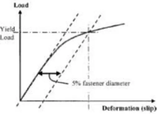
Alternatively, the American Society of Civil Engineers has published a ‘‘Standard for Load and Resistance Factor Design for Engineered Wood Construction’’ that is technically equivalent to international LRFD (Load and Resistance Factor Design) codes. Informal information implies that at present very limited use is made of LRFD in the U.S. As defined in the U.S., the yield limit load and material properties that enter the equations have a very specific and unique meaning, embedment strength of wood beneath a fastener and the yield moment for a fastener are 5% offset values (Smith & Foliente, 2002). The yield point (Figure 3.6) lies between the proportional limit and the ultimate strength of the connection.
Figure 3.6 Five percent offset method for defining joint "yield limit load" (Smith & Foliente, 2002)
The European Committee for Standardisation based on Belgium has published a model design code ‘‘Structural Timber Design Code’’ with the designation Eurocode 5, which is in LRFD format. The dowel bearing strength is called in European code as embedment strength.
Wilkinson (1991) carried out a study about the dowel bearing strength. The authors defined bearing strength as the maximum test load. Results showed that bearing strength for bolts loaded parallel to grain is related to specific gravity; for bolts loaded perpendicular to grain, bearing strength is related to specific gravity and bolt diameter. Bearing strength for nails is dependent upon specific gravity and is independent of loading direction and nail diameter.
The likeness between these two codes led to the consideration and individualization of each type of rupture analytically through considerations of equilibrium of efforts. The
33 different modes of rupture or failure modes considered by the American Code are showed in the Figure 3.7.
Figure 3.7 Various combinations of wood-bearing and fastener-bending yields for (a) two member connections and (b) three member connections (Rammer, 2001)
3.10. Numerical Models in Timber Connections
The embedding strength of wood and the yield moment of the dowel depend on the method of evaluation. Some studies have compare the values calculated by the yield theory (Johansen’s Theory) with the experimental results. However, this theory does not consider the plastic behaviour (e.g. hardening of the dowel and embedding of wood) after yielding. (Sawata & Yasumura, 2002)
The finite element (FE) nonlinear analysis is a numerical analysis that can approximate the load-slip behaviour of dowel-type joints considering the elastoplastic behaviour of wood and dowels. Sawata & Yasumura (2002) carried out a study using FE nonlinear analysis of bolted timber joints, where the yielding of the bolt appears at the boundry between steel plate and the wood. In this study shows that the yield and the ultimate strenghts of the joiny can be stimated by the yield theory when is properly applied. Other investigation carried out by Hong & Barrett (2010) use a 3D FE analysis of single nail connections for simulating the wood crushing behaviour under a dowel. This phenomen is difficult using the conventional methods. The application of 3D models help to simulate the loacalized wood crushing behaviour under a dowel.
By other hand, the load-bearing behaviour of a timber connections is a complex mechanism. Resch & Kaliske (2010) developed finite elements (FE) model that allows the failure behaivour and the possibility of simulating multiple fasteners. The advantages of FE models is the possibility to carry out comprehensive parameter studies for different boundary conditions, with the aim of determine the ultimate loads and failure mechanisms.