UNIVERSIDADE FEDERAL DE SÃO CARLOS
CENTRO DE CIÊNCIAS EXATAS E DE TECNOLOGIA
DEPARTAMENTO DE QUÍMICA
PROGRAMA DE PÓS-GRADUAÇÃO EM QUÍMICA
“
Tris(trimethylsilyl)silane and Visible-Light
Irradiation: A New Metal- and Additive-Free
Photochemical Process for the Synthesis of
Indoles and Oxindoles”
Gustavo Piva da Silva*
Dissertação apresentada como parte dos requisitos para obtenção do título de MESTRE EM QUÍMICA, área de concentração: QUÍMICA ORGÂNICA.
Orientador: Prof. Dr. Márcio Weber Paixão
* bolsista CNPq
Ficha catalográfica elaborada pelo DePT da Biblioteca Comunitária UFSCar Processamento Técnico
com os dados fornecidos pelo(a) autor(a)
S586t
Silva, Gustavo Piva da
Tris(trimethylsilyl)silane and visible-light irradiation : a new metal- and additive-free photochemical process for the synthesis of indoles and oxindoles / Gustavo Piva da Silva. -- São Carlos : UFSCar, 2016.
166 p.
Dissertação (Mestrado) -- Universidade Federal de São Carlos, 2016.
I dedicate this work to my parents, brother, sister,
my entire family, and my girlfriend,
for all of the support they have provided me.
“
The measure of intelligence is the ability to change
”
Acknowledgements
I would like to thank my parents, Angela and Nelson, and my brothers Mariana and Vitor, for being my biggest motivation and example for always being by my side, and be the basis of everything I am. And also thank all my family for all the support. My girlfriend/fiancée Fernanda for all understanding, patience, encouragement, and especially the companionship at all times, and also her family that was always by my side.
Professor Márcio for all the guidance and tireless willingness to teach and discuss Chemistry and every incentive to scientific and personal growth. Professors Arlene and Ricardo for their cooperation and assistance in day-to-day laboratory and during the development of the work. Professor Rebecca Davis (University of Manitoba) and her group, for the opportunity to work, study, and unique learning experience.
Friends Akbar Ali, and Rodrigo Cesar (Jacaré), who were fundamental in developing the project and the immense contributions to the work obtain adequate quality. Also, thank you for all the professional discussion and moments of fun. To all friends of the laboratory that were present throughout this trajectory, contributing to discussions, helps, and of course for many moments of fun. Friends of the República Ponto V, and Valinhos-SP for providing the best moments of fun and partnership.
To all the professors and staff of DQ (UFSCar – SP - Brazil) and University of Manitoba (Canada) that somehow contributed to this work.
The all from whom I learned and contributed to my training.
ix
List of Abbreviations
Bu3N Tributylamine
CT Charge transfer
DCM Dichloromethane
DDQ 2,3-Dichloro-5,6-dicyano-1,4-benzoquinone
DMF Dimethylformamide
DMSO Dimethylsulfoxide
E Energy
EDA Electron donor-acceptor
ESA Excited state absorption
EtOAc Ethyl acetate
FDA Food and drug administration
GC-MS Gas chromatography – mass spectrometry
HOMO Highest occupied molecular orbital
IC Internal conversion
ISC Intersystem crossing
LUMO Lowest unoccupied molecular orbital
MeCN Acetonitrile
MEOD Deuterated methanol
PC Photocatalyst
S Spin multiplicity
THF Tetrahydrofurane
TTMSS Tris(trimethylsilyl)silane
UV Ultraviolet-Visible
H Planck’s constant
Frequency
Λ Wavelength
xi
List of Tables
TABLE 1: Optimization studies: Effect of the TTMSS loading. ... 57
TABLE 2: Optimization studies: Solvent screening. ... 58
TABLE 3: Optimization studies: Additional proton source. ... 59
TABLE 4: Optimization studies: Effect of the structure –N-protecting group. ... 60
TABLE 5: Kinetics studies: Area x Concentration of N-tosyl-propargyl aniline. ... 69
TABLE 6: Kinetics studies: Area x Concentration of TTMSS. ... 70
xiii
List of Figures
FIGURE 1: HOMO-LUMO diagram. ... 29
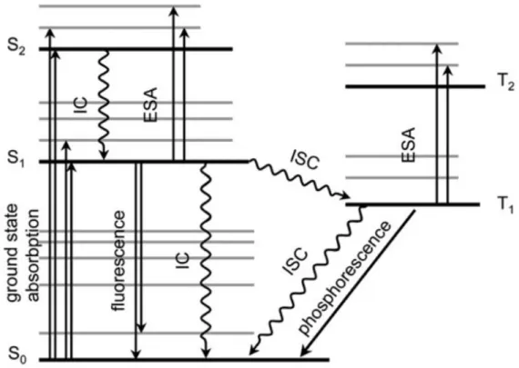
FIGURE 2: Energy level diagram and summary of photochemical processes (Jablonski diagram: IC – internal conversion, ESA – excited state absorption, ISC – intersystem crossing). ... 31
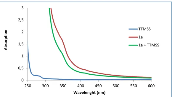
FIGURE 3: Absorption spectra of the separated reagents of the model reaction, and the reaction mixture. ... 65
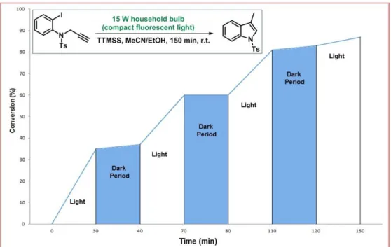
FIGURE 4: Successive intervals of irradiation and dark periods for the model reaction. ... 66
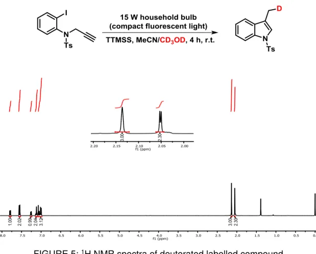
FIGURE 5: 1H NMR spectra of deuterated labelled compound. ... 67
FIGURE 6: Calibration curve of N-tosyl-propargyl aniline. ... 69
FIGURE 7: Calibration curve of TTMSS. ... 70
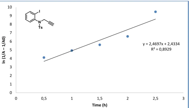
FIGURE 8: First order applied to N-tosyl-propargyl aniline... 71
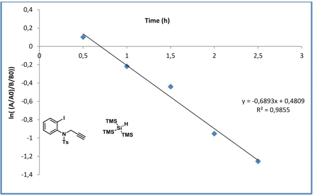
FIGURE 9: First order applied to TTMSS. ... 71
FIGURE 10: Second order applied to N-tosyl-propargyl aniline. ... 72
FIGURE 11: Second order applied to TTMSS. ... 72
FIGURE 12: Second order overall – first order with respect to each reagent. ... 73
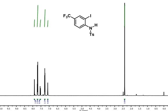
FIGURE 13: 1H NMR spectrum of 46a precursor, 400 MHz, CDCl3. ... 109
FIGURE 14: 13C NMR spectrum of 46a precursor, 100 MHz, CDCl3. ... 109
FIGURE 15: 1H NMR spectrum of 46b precursor, 400 MHz, CDCl3. ... 110
FIGURE 16: 13C NMR spectrum of 46b precursor, 100 MHz, CDCl3. ... 110
FIGURE 17: 1H NMR spectrum of 46c precursor, 400 MHz, CDCl3. ... 111
FIGURE 18: 13C NMR spectrum of 46c precursor, 100 MHz, CDCl3. ... 111
FIGURE 19: 1H NMR spectrum of 46f precursor, 400 MHz, CDCl3. ... 112
FIGURE 20: 13C NMR spectrum of 46f precursor, 100 MHz, CDCl3. ... 112
FIGURE 21: 1H NMR spectrum of 46h precursor, 400 MHz, CDCl3. ... 113
FIGURE 22: 13C NMR spectrum of 46h precursor, 100 MHz, CDCl3. ... 113
FIGURE 23: 1H NMR spectrum of 46j precursor, 400 MHz, CDCl3. ... 114
FIGURE 24: 1H NMR spectrum of 46k precursor, 400 MHz, CDCl3. ... 114
FIGURE 25: 13C NMR spectrum of 46k precursor, 100 MHz, CDCl3. ... 115
FIGURE 26: 1H NMR spectrum of 46l precursor, 400 MHz, CDCl3. ... 115
FIGURE 27: 13C NMR spectrum of 46l precursor, 100 MHz, CDCl3. ... 116
xiv
FIGURE 29: 1H NMR spectrum of 46o precursor, 400 MHz, CDCl3. ... 117
FIGURE 30: 13C NMR spectrum of 46o precursor, 100 MHz, CDCl3. ... 117
FIGURE 31: 1H NMR spectrum of 46a, 400 MHz, CDCl3. ... 118
FIGURE 32: 13C NMR spectrum of 46a, 100 MHz, CDCl3. ... 118
FIGURE 33: 1H NMR spectrum of 46b, 400 MHz, CDCl3. ... 119
FIGURE 34: 13C NMR spectrum of 46b, 100 MHz, CDCl3. ... 119
FIGURE 35: 1H NMR spectrum of 46c, 400 MHz, CDCl3. ... 120
FIGURE 36: 13C NMR spectrum of 46c, 100 MHz, CDCl3. ... 120
FIGURE 37: 1H NMR spectrum of 46d, 400 MHz, CDCl3. ... 121
FIGURE 38: 1H NMR spectrum of 46e, 400 MHz, CDCl3. ... 121
FIGURE 39: 13C NMR spectrum of 46e, 100 MHz, CDCl3. ... 122
FIGURE 40: 1H NMR spectrum of 46f, 400 MHz, CDCl3. ... 122
FIGURE 41: 13C NMR spectrum of 46f, 100 MHz, CDCl3. ... 123
FIGURE 42: 1H NMR spectrum of 46g, 400 MHz, CDCl3. ... 123
FIGURE 43: 1H NMR spectrum of 46h, 400 MHz, CDCl3. ... 124
FIGURE 44: 13C NMR spectrum of 46h, 100 MHz, CDCl3. ... 124
FIGURE 45: 1H NMR spectrum of 46k, 400 MHz, CDCl3. ... 125
FIGURE 46: 13C NMR spectrum of 46k, 100 MHz, CDCl3. ... 125
FIGURE 47: 1H NMR spectrum of 46l, 400 MHz, CDCl3. ... 126
FIGURE 48: 13C NMR spectrum of 46l, 100 MHz, CDCl3. ... 126
FIGURE 49: 1H NMR spectrum of 46m, 400 MHz, CDCl3. ... 127
FIGURE 50: 1H NMR spectrum of 46n, 400 MHz, CDCl3. ... 127
FIGURE 51: 13C NMR spectrum of 46n, 100 MHz, CDCl3. ... 128
FIGURE 52: 1H NMR spectrum of 46o, 400 MHz, CDCl3. ... 128
FIGURE 53: 13C NMR spectrum of 46o, 100 MHz, CDCl3. ... 129
FIGURE 54: 1H NMR spectrum of 48c precursor, 400 MHz, CDCl3. ... 129
FIGURE 55: 13C NMR spectrum of 48c precursor, 100 MHz, CDCl3. ... 130
FIGURE 56: 1H NMR spectrum of 48e precursor, 400 MHz, CDCl3. ... 130
FIGURE 57: 13C NMR spectrum of 48e precursor, 100 MHz, CDCl3. ... 131
FIGURE 58: 1H NMR spectrum of 48f precursor, 400 MHz, CDCl3. ... 131
FIGURE 59: 13C NMR spectrum of 48f precursor, 100 MHz, CDCl3. ... 132
FIGURE 60: 1H NMR spectrum of 48g precursor, 400 MHz, CDCl3. ... 132
FIGURE 61: 13C NMR spectrum of 48g precursor, 100 MHz, CDCl3. ... 133
xv
FIGURE 63: 1H NMR spectrum of 48i precursor, 400 MHz, CDCl3. ... 134
FIGURE 64: 13C NMR spectrum of 48i precursor, 100 MHz, CDCl3. ... 134
FIGURE 65: 1H NMR spectrum of 48a, 400 MHz, CDCl3. ... 135
FIGURE 66: 1H NMR spectrum of 48b, 400 MHz, CDCl3. ... 135
FIGURE 67: 13C NMR spectrum of 48b, 100 MHz, CDCl3. ... 136
FIGURE 68: 1H NMR spectrum of 48c, 400 MHz, CDCl3. ... 136
FIGURE 69: 13C NMR spectrum of 48c, 100 MHz, CDCl3. ... 137
FIGURE 70: 1H NMR spectrum of 48d, 400 MHz, CDCl3. ... 137
FIGURE 71: 13C NMR spectrum of 48d, 100 MHz, CDCl3. ... 138
FIGURE 72: 1H NMR spectrum of 48e, 400 MHz, CDCl3. ... 138
FIGURE 73: 13C NMR spectrum of 48e, 100 MHz, CDCl3. ... 139
FIGURE 74: 1H NMR spectrum of 48f, 400 MHz, CDCl3. ... 139
FIGURE 75: 13C NMR spectrum of 48f, 100 MHz, CDCl3. ... 140
FIGURE 76: 1H NMR spectrum of 48g, 400 MHz, CDCl3. ... 140
FIGURE 77: 1H NMR spectrum of 48h, 400 MHz, CDCl3. ... 141
FIGURE 78: 13C NMR spectrum of 48h, 100 MHz, CDCl3 ... 141
FIGURE 79: 1H NMR spectrum of 48i, 400 MHz, CDCl3 ... 142
FIGURE 80: 13C NMR spectrum of 48i, 100 MHz, CDCl3 ... 142
FIGURE 81: 1H NMR spectrum of 47a, 400 MHz, CDCl3. ... 143
FIGURE 82: 13C NMR spectrum of 47a, 100 MHz, CDCl3. ... 143
FIGURE 83: 1H NMR spectrum of 47b, 400 MHz, CDCl3. ... 144
FIGURE 84: 13C NMR spectrum of 47b, 100 MHz, CDCl3. ... 144
FIGURE 85: 1H NMR spectrum of 47c, 400 MHz, CDCl3. ... 145
FIGURE 86: 13C NMR spectrum of 47c, 100 MHz, CDCl3. ... 145
FIGURE 87: 1H NMR spectrum of 47d, 400 MHz, CDCl3. ... 146
FIGURE 88: 13C NMR spectrum of 47d, 100 MHz, CDCl3. ... 146
FIGURE 89: 1H NMR spectrum of 47e, 400 MHz, CDCl3. ... 147
FIGURE 90: 13C NMR spectrum of 47e, 100 MHz, CDCl3. ... 147
FIGURE 91: 1H NMR spectrum of 47f, 400 MHz, CDCl3. ... 148
FIGURE 92: 13C NMR spectrum of 47f, 100 MHz, CDCl3. ... 148
FIGURE 93: 1H NMR spectrum of 47g, 400 MHz, CDCl3. ... 149
FIGURE 94: 13C NMR spectrum of 47g 100 MHz, CDCl3. ... 149
FIGURE 95: 1H NMR spectrum of 47h, 400 MHz, CDCl3. ... 150
xvi
FIGURE 97: 1H NMR spectrum of 47i, 400 MHz, CDCl3. ... 151
FIGURE 98: 13C NMR spectrum of 47i, 100 MHz, CDCl3. ... 151
FIGURE 99: 1H NMR spectrum of 47j, 400 MHz, CDCl3. ... 152
FIGURE 100: 13C NMR spectrum of 47j, 100 MHz, CDCl3.... 152
FIGURE 101: 1H NMR spectrum of 47k, 400 MHz, CDCl3.... 153
FIGURE 102: 13C NMR spectrum of 47k, 100 MHz, CDCl3. ... 153
FIGURE 103: 1H NMR spectrum of 47l, 400 MHz, CDCl3. ... 154
FIGURE 104: 13C NMR spectrum of 47l, 100 MHz, CDCl3. ... 154
FIGURE 105: 1H NMR spectrum of 47m, 400 MHz, CDCl3. ... 155
FIGURE 106: 13C NMR spectrum of 47m, 100 MHz, CDCl3. ... 155
FIGURE 107: 1H NMR spectrum of 47n, 400 MHz, CDCl3. ... 156
FIGURE 108: 13C NMR spectrum of 47n, 100 MHz, CDCl3. ... 156
FIGURE 109: 1H NMR spectrum of 47o, 400 MHz, CDCl3. ... 157
FIGURE 110: 13C NMR spectrum of 47o, 100 MHz, CDCl3. ... 157
FIGURE 111: 1H NMR spectrum of 49a, 400 MHz, CDCl3. ... 158
FIGURE 112: 13C NMR spectrum of 49a, 100 MHz, CDCl3. ... 158
FIGURE 113: 1H NMR spectrum of 49b, 400 MHz, CDCl3. ... 159
FIGURE 114: 13C NMR spectrum of 49b, 100 MHz, CDCl3. ... 159
FIGURE 115: 1H NMR spectrum of 49c, 400 MHz, CDCl3.... 160
FIGURE 116: 13C NMR spectrum of 49c, 100 MHz, CDCl3. ... 160
FIGURE 117: 1H NMR spectrum of 49d, 400 MHz, CDCl3. ... 161
FIGURE 118: 13C NMR spectrum of 49d, 100 MHz, CDCl3. ... 161
FIGURE 119: 1H NMR spectrum of 49e, 400 MHz, CDCl3. ... 162
FIGURE 120: 13C NMR spectrum of 49e, 100 MHz, CDCl3. ... 162
FIGURE 121: 1H NMR spectrum of 49f, 400 MHz, CDCl3. ... 163
FIGURE 122: 13C NMR spectrum of 49f, 100 MHz, CDCl3. ... 163
FIGURE 123: 1H NMR spectrum 49g, 400 MHz, CDCl3. ... 164
FIGURE 124: 13C NMR spectrum of 49g, 100 MHz, CDCl3. ... 164
FIGURE 125: 1H NMR spectrum of 49h, 400 MHz, CDCl3. ... 165
FIGURE 126: 13C NMR spectrum of 49h, 100 MHz, CDCl3. ... 165
FIGURE 127: 1H NMR spectrum of 49i, 400 MHz, CDCl3. ... 166
xvii
List of Schemes
SCHEME 1: Metal-free process for the synthesis of indoles and oxindoles. ... xix
SCHEME 2: Metodologia para a síntese de indóis e oxindóis livre de metais. ... xxi
SCHEME 3: Santonin: Photochemical modifications. ... 26
SCHEME 4: Cyclization reaction mediated by sunlight. ... 27
SCHEME 5: [2+2] Photocycloaddition reaction. ... 28
SCHEME 6: Photochemical route to access cyclopropane systems. ... 33
SCHEME 7: Photochemical alkylation of indoles driven by an EDA complex. ... 34
SCHEME 8: General representations for a photoinduced electron transfer mediated (A) a Photocatalyst and (B) Electron donor-acceptor (EDA complex). ... 35
SCHEME 9: Alkylation of indoles driven by an EDA complex. ... 36
SCHEME 10: Radical-nucleophilic substitution reactions mediated by EDA complexes. ... 37
SCHEME 11: α-trifluoromethylation of enolsilanes mediated by visible light. ... 38
SCHEME 12: Visible light-mediated direct arylation of heteroarenes using diaryliodonium salts in the absence of a photocatalyst. ... 38
SCHEME 13: Visible light mediated transformations with polyhalomethanes providing α-CH activation of tetrahydroisoquinoline. ... 39
SCHEME 14: Pharmaceutical active compounds containing the indole scaffold... 41
SCHEME 15: First catalytic asymmetric Fischer indolization. ... 42
SCHEME 16: Synthesis of functionalized indoles via palladium-catalyzed aerobic oxidative cycloisomerization. ... 43
SCHEME 17: Proposed mechanism for the photocatalytic N-arylindoles synthesis. . 44
SCHEME 18: Reduction of aryl iodide and intramolecular reductive cyclization. ... 45
SCHEME 19: Pharmaceutically active oxindoles. ... 46
SCHEME 20: Palladium-catalyzed oxindole synthesis and possible mechanistic pathways. ... 47
SCHEME 21: Metal-free synthesis of 2‑oxindoles via PhI(OAc)2‑mediated oxidative C−C bond formation. ... 48
SCHEME 22: Visible light induced radical cyclization of o-iodophenylacrylamides. .. 49 SCHEME 23: Oxindole synthesis. (A) Synthesis of 3,3-disubstituted oxindoles by
xviii
N-arylacrylamides. (B) Direct synthesis of sulfonated oxindoles from N
-arylacrylamides and arylsulfinic acids using visible light by means of a cascade
C-S/C-C formation process. ... 51
SCHEME 24: Project goal ... 53
SCHEME 25: Tris(trimethylsilil)silane as a radical promoter. ... 56
SCHEME 26: Substrate scope for the visible-light-mediated indole synthesis. ... 61
SCHEME 27: Formal synthesis of Dolasetron. ... 63
SCHEME 28: Controlled experiments. ... 63
SCHEME 29: Proposed mechanism for the visible-light-mediated indole synthesis. 74 SCHEME 30: Simplified retrosynthetic analysis. ... 75
SCHEME 31: Substrate scope for the visible-light-mediated oxindole synthesis. ... 77
SCHEME 32: Scope limitation of the methodology. ... 77
SCHEME 33: Synthesis of N-tosyl-protected aniline. ... 90
SCHEME 34: Synthesis of N-tosyl-propargyl aniline. ... 93
SCHEME 35: Synthesis of N-acrylamides. ... 96
xix
Abstract
TRIS(TRIMETHYLSILYL)SILANE AND VISIBLE-LIGHT
IRRADIATION: A NEW METAL- AND ADDITIVE-FREE PHOTOCHEMICAL PROCESS FOR THE SYNTHESIS OF INDOLES AND OXINDOLES
A combined tris(trimethylsilyl)silane and visible-light-promoted intramolecular reductive cyclization protocol for the synthesis of indoles and oxindoles has been developed (Scheme 1).1 This straightforward and efficient protocol shows a
broad functional-group tolerance and enables rapid and practical synthesis of functionalized nitrogen-based heterocycles in high/moderate yields under additive and metal-free, mild photochemical conditions. Besides the synthetic developments, the reaction mechanism was also investigated by a set of controlled experiments and UV-visible analyses, as well as kinetic study.2 From these studies, we have concluded that
the reaction pathway for this strategy occurs through an Electron Donor-Acceptor (EDA) complex.3
SCHEME 1: Metal-free process for the synthesis of indoles and oxindoles.
1 NGUYEN, J. D.; D’AMATO, E. M.; NARAYANAM, J. M. R.; STEPHENSON, C. R. J. “Engaging unactivated alkyl, alkenyl and aryl iodides in visible-light-mediated free radical reactions”. Nat. Chem.,
4: 854, 2012.
2SILVA, G. P.; ALI, A.; SILVA, R. C.; JIANG, H.; PAIXÃO, M. W. “Tris(trimethylsilyl)silane and visible -light irradiation: a new metal- and additive-free photochemical process for the synthesis of indoles and
oxindoles”. Chem. Commun., 51: 15110, 2015.
3 LIMA, C. G. S.; LIMA, T. D. M.; DUARTE, M.; JURBERG, I. D.; PAIXÃO, M. W. “Organic Synthesis Enabled by Light-Irradiation of EDA Complexes: Theoretical Background and Synthetic Applications”.
xxi
Resumo
LUZ VISÍVEL E TRIS(TRIMETILSILIL)SILANO: UM NOVO PROCESSO FOTOQUÍMICO SEM ADICÃO DE METAL E ADITIVO PARA A SÍNTESE DE INDÓIS E OXINDÓIS
Uma nova metodologia para síntese de indóis e oxindóis foi desenvolvida através de um processo de ciclização redutiva intramolecular utilizando uma combinação da luz visível e tris(trismetilsilil)silano (Scheme 2).1 Este protocolo
sintético mostrou-se eficiente e abrangente a diversos substratos funcionalizados, permitindo assim uma rápida e prática síntese de compostos nitrogenados heterocíclicos com altos/moderados rendimentos diante de uma condição fotoquímica livre de metais, bem como aditivos. Além do desenvolvimento sintético, o mecanismo da reação também foi investigado por uma série de experimentos controlados e estudos e espectroscópicos, bem como estudos cinéticos.2 A partir destes estudos,
concluímos que o caminho reacional para esta estratégia ocorre através de um complexo doador-aceptor (EDA).3
xxiii
Summary
Acknowledgements ... xii
List of Abbreviations ... ix
List of Tables ... xi
List of Figures ... xiii
List of Schemes ...xvii
Abstract ... xix
Resumo ... xxi
Summary ... xxiii
1 Introduction ... 25
1.1 Organic Photochemistry ... 25 1.2 Excited States ... 27 1.3 Electron Donor-Acceptor Complex ... 34 1.4 Indole and Oxindole Synthesis ... 40
2 Project Goals ... 53
3 Results and Discussion ... 55
3.1 Optimization Studies ... 55 3.2 Scope Evaluation ... 60 3.3 Mechanistic Insights ... 63 3.4 Kinetic Studies ... 66 3.5 Oxindole Synthesis ... 75
4 Conclusion ... 79
5 References... 81
6 Experimental Section ... 89
6.1 General Experimental Information ... 89 6.2 General Experimental Procedures ... 90 6.2.1 Preparation of the starting materials ... 90 6.2.1.1 Preparation of the N-tosyl-protected aniline ... 90
xxiv
6.2.1.3 Preparation of the N-acrylamides ... 96
6.2.1.4 Preparation of the N-benzyl-acrylamides (Compounds 48a-i) ... 98
6.2.1.5 General procedure for the photochemical intramolecular cyclization reaction 100
6.2.1.5.1 Indole Synthesis ... 100 6.2.1.5.2 Oxindole Synthesis ... 105
25
1 Introduction
1.1 Organic Photochemistry
Chemical transformations can be accomplished using various sources of energy, namely thermal, microwave, ultrasonic, electrochemical and light, among others. The energy source plays an important role in the development of any new chemical process, and more specifically, in the achievement targeted molecules in a more efficient and selective way. In the last few years, a higher specificity has been required from the energy source in terms of breaking and forming chemical bonds. In this context, light has become a key energy source among the several existing ones, as it fulfills most of the requirements for modern chemical transformations.4
Light has long been used as an energy source in chemical process, but only in the 1960s it has found applications in the promotion of organic transformations, and as a result, many useful and fascinating reactions were uncovered. As a consequence, photochemistry is currently an important synthetic tool that enables the synthesis of fine chemicals.5 However, the direct use of visible light in organic reactions
is limited owing to the ability of organic molecules to absorb photons in the visible spectra. In order to solve this long-standing problem, many photo-catalysts such as metals (Ru, Ir, Rh) and dyes have been exploited.6
4PITRE, S. P.; MCTIERNAN, C. D.; SCAIANO, J. C. “Understanding the Kinetics and Spectroscopy of Photoredox Catalysis and Transition-Metal-Free Alternatives”. Acc. Chem. Res.,49:1320, 2016.
5(a) HOFFMANN, N. “Photochemical Reactions as Key Steps in Organic Synthesis”. Chem. Rev.108:
1052, 2008. b) XUAN, J.; XIAO, W. J. “Visible-light photoredox catalysis”. Angew. Chem. Int. Ed.,51:
6828, 2012. (c) CAREY, A. F.; SUNDBERG, R. J. Advanced Organic Chemistry, 5ª ed., Springer, 2007.
6 (a) YOON, T. P.; ISCHAY, M.; DU, J. “Visible light photocatalysis as a greener approach to
photochemical synthesis”. Nat. Chem., 2: 527, 2010. (b) BRACHET, E.; GHOSH, T.; GHOSH, I.;
KÖNIG, B. “Visible light C–H amidation of heteroarenes with benzoyl azides”. Chem. Sci.,6: 987, 2015.
(c) XIAO, Q. H.; JIA, R. C.; QIANG, W.; FENG, L. L.; QIAO, H. D.; ANDRÉ, M. B.; WEN, J. X.
“Photocatalytic Generation of N-Centered Hydrazonyl Radicals: A Strategy for Hydroamination of β, γ
-Unsaturated Hydrazones”. Angew. Chem. Int. Ed., 53: 12163, 2014. (d) KARAKAYA, I.; PRIMER, D.
N.; MOLANDER, G. A. “Photoredox Cross-Coupling: Ir/Ni Dual Catalysis for the Synthesis of Benzylic
Ethers”. Org. Lett., 17: 3294, 2015. (e) TUCKER, J. W.; NGUYEN, J. D.; NARAYANAM, J. M. R.;
KRABBE, S. W.; STEPHENSON, C. R. J. “Tin-free radical cyclization reactions initiated by visible light
photoredox catalysis”. Chem. Commun., 46:4985, 2010. (f) FARNEY, E. P.; YOON, T. P. “Visible-light sensitization of vinyl azides by transition-metal photocatalysis”. Angew. Chem. Int. Ed.,53: 793, 2014.
(g) YASU, Y.; ARAI, Y.; TOMITA, R.; KOIKE, T.; AKITA, M. “Highly regio- and diastereoselective synthesis of CF3 - substituted lactones via photoredox-catalyzed carbolactonization of alkenoic acids”.
26
A remarkable example and perhaps the earliest known photoreaction involving an organic compound is that of Santonin (1). Since its first exposure to sunlight in 1834 by Hermarin Trommsdorff, curious observations related to the changes in its physical properties have been made, showing the extent of the interaction between light and matter. This case triggered the interest of many researchers regarding the investigation of Santonin photoproducts. In this way, the Santonin photoproducts were completely understood and elucidated in 1950s and 1960s, completing the photochemical puzzle that dated back to the 1830s. The three photoproducts of this process, which are lumisantonin (2), its isomer (3), and photosantonic acid (4), are showed in Scheme 3.7
SCHEME 3: Santonin: Photochemical modifications.
The discovery of the photoproducts from Santonin was an important breakthrough in the course of organic photochemistry and paved the way for a variety of procedures that elucidated the interaction between matter and light. Fukuyama et.al, for instance, disclosed the photochemically induced cyclization reaction of the brominated indole (5) to achieve the product (6) in quantitative yield (Scheme 4).8
7ROTH, H. D. “The Beginnings of Organic Photochemistry”. Angew. Chem. Int. Ed., 28: 1193, 1989. 8KOBAYASHI, Y.; FUJIMOTO, T.; FUKUYAMA, T. “Stereocontrolled total synthesis of (+)-K252a”. J.
27
SCHEME 4: Cyclization reaction mediated by sunlight.
1.2 Excited States
Following the concepts of light-matter interaction, organic molecules may absorb light and reach electronically excited states. As a result of such excitation, the distribution of electrons in the molecule become significantly different when compared to its ground state. Consequently, molecules in the excited state present different properties than that of the ground state, particularly the reactivity; since the excited states characterize new energetic levels for the molecules, the generation of new reactive centers in the electronically excited species gives rise to a broadening in the reaction spectrum.5
The energy supplied by a particular wavelength of light can be calculated from the fundamental Planck's equation:
𝑬 = 𝒉𝝊 = 𝒉 𝝀𝒄
In this equation, E is the energy of a light particle, the so-called photon,
is the frequency of the radiation, h the Planck’s constant, c the speed of light and λ
the wavelength of the radiation. Replacing the constants h and c in the second form of
the equation, the energy of the radiation can be easily calculated in kcal mol-1 using
the following equation:
28
The electromagnetic radiation with wavelengths ranging from 800 nm (near infrared) to 150 nm (far UV) is the one primarily used in photochemistry, as this range corresponds to photon energies varying from 37 to 200 kcal mol-1; for example,
the light with a 254 nm wavelength affords 112.6 kcal mol-1 of energy, which is enough
to break most single bonds.5
In this context, several reports can be found in literature demonstrating how efficiently organic molecules interact with light and absorb it. A very interesting example of the application of this phenomena are [2+2] photocycloadditions, a class of reactions that affords cyclobutanes. The study of the intermediates as well as final products of this reaction are a very well developed field in organic synthesis.9 Lex et
al., for instance, reported a photochemical protocol followed by a sequential hydrolysis step to achieve α-amino-β-hydroxy carboxylic esters (9) from 5-methoxyoxazoles (7), and aldehydes (8) as showed in Scheme 5.10
SCHEME 5: [2+2] Photocycloaddition reaction.
Since the reactivity of the molecules changes considerably when exposed to light irradiation, the comprehension of these exited species and their further transformations have become a very attractive subject. The fundaments of this chemistry rely on important events e.g. light absorption, light emission (luminescence), and excited-state reactions (electron transfer, energy transfer, and bond breaking).5, 11
9 (a) PATAI Series: The Chemistry of Functional Groups; Rappoport, Z., Series Ed.; Wiley: Chichester, 2005; The Chemistry of Cyclobutanes Parts 1 and 2 (Rappoport, Z., LIEBMAN, J. F.). (b) NAMYSLO,
J. C.; KAUFMANN, D. E. “The application of cyclobutane derivatives in organic synthesis”. Chem. Rev.,
103: 1485, 2003.
10 GRIESBECK, A. G.; BONDOCK, S.; LEX, J. “Synthesis of erythro-alpha-amino beta-hydroxy carboxylic acid esters by diastereoselective photocycloaddition of 5-methoxyoxazoles with aldehydes”.
J. Org. Chem.,68: 9899, 2003.
11 (a) COYLE, J. D. Introduction to Organic Photochemistry. John Wiley & Sons Ltd, 1989. (b) WARDLE, B. Principles and Applications of Photochemistry. John Wiley & Sons Ltd, 2009. (c) KLÁN, P.; WIRZ, J. Photochemistry of Organic Compounds. John Wiley & Sons Ltd, 2009. (d) PAVIA, D. L.; LAMPMAN, G.
M.; KRIS, G. S.; VYVYAN, J. R. Introduction to Spectroscopy. 4ª ed., 2001 Brooks/Cole, Cengage
29
When a molecule absorbs light in the UV-Vis region, an electron is promoted from the highest-energy occupied molecular orbital (HOMO) to the lowest-energy unoccupied molecular orbital (LUMO), which results in an excited state molecule. One requirement for a molecule to absorb light is that the energy of the photon matches the energy difference between the orbitals, ∆E = Ephoton = h = hc/λ;
photons having insufficient energy will be transmitted. Therefore, the absorbance of light in different wavelengths provides invaluable experimental information about the energy difference and spacing between orbitals.11
In the view that the molecules possess many occupied and unoccupied molecular orbitals, there are many possible transitions to promote an electron from a higher-energy occupied to lower-energy unoccupied orbital. However, only a few of these molecular orbitals are involved in light absorption events. Based on the frontier molecular orbitals, the lowest-energy photon corresponds to the transition of an electron from the highest occupied molecular orbital (HOMO) to the lowest unoccupied molecular orbital (LUMO). The HOMO-LUMOenergy gap(∆E) typically determines the color of light seen transmitted through a solution. Transitions of an electron from lower-energy occupied orbitals into higher-lower-energy unoccupied orbitals necessarily require higher-energy photons. Figure 1 shows an example of a HOMO-LUMO excitation.11
FIGURE 1: HOMO-LUMO diagram.
30
many transition metal ions). The highest energy electrons occupy the HOMO and these electrons are paired with opposite spin (+½, -½), being the total spin of the electrons S= 0 and the multiplicityof the ground state a singlet.11
The excitation of a photon having an energy that corresponds to the HOMO-LUMO energy gap would result in an excited state that is also a singlet. In a singlet excited state (S) the excited electrons retain opposite spins, while in triplet excited states (T) they have parallel spins. Thus, both excited states could happen during the electronic excitation. However, it is important to mention that the electrons do not undergo spin inversion at the time of the excitation, since it is forbidden by quantum mechanical selection rules, which state that there must be the conservation of spin during the excitation process. Subsequent spin state changes may occur, but as separate events from excitation. In the initial excited state, the unpaired electrons have opposite spins, and therefore, are in a singlet state (S). Thus, a very short time
(10−15 s) is usually required for excitation, during which the molecule does not undergo
any nuclear changes and there is also no change in the spin state of the promoted electron. After the excitation, however, these changes may occur rapidly.11
When an electron excitation takes place, many events known as photophysical/chemical processes may occur. Such processes are related to the behavior of the electron when it goes back to the ground state after a photoexcitation. These pathways are explained below in the Jablonski diagram (Figure 2).11, 12
The events in the diagram can be explained as follows:13
I. A molecule in the S1 state can cascade down through the vibrational levels of
the S0 state and thus return to the ground state by releasing its energy in small
increments to the environment, though this process is generally very slow because of the large amount of energy. The process is called internal conversion (IC). As it is slow proceeds, most molecules in the S1 state can adopt
other returning pathways.
12ZIMMERMANN, J.; ZEUG, A.; RODER, B. “A generalization of the Jablonski diagram to account for polarization and anisotropy effects in time-resolved experiments”. Phys. Chem. Chem. Phys.,5: 2964,
2003.
31
FIGURE 2: Energy level diagram and summary of photochemical processes (Jablonski diagram: IC – internal conversion, ESA – excited state absorption, ISC –
intersystem crossing).
II. A molecule in the S1 state decrease to some low vibrational level of the S0 state
at once by releasing the absorbed energy in the form of light. This process, which generally happens within 10-9 s, is called fluorescence. Due to the
possibility of fluorescence, either the chemical reaction of the S1 state must take
place very fast or fluorescence will occur before the reaction.
III. Mostly molecules (not all) in the S1 state can undergo an intersystem crossing
(ISC) to the lowest state, the triplet T1. The intersystem crossing from the singlet
to the triplet state is a “forbidden” pathway on account of the angular momentum, but it often occurs by compensations elsewhere in the system. Since intersystem crossing occurs without loss of energy and the singlet state often has a higher energy than the corresponding triplet state, the energy must be somehow eliminated. The higher probability for this process to happen is when the S1 molecule crosses to a T1 state at a high vibrational level and then
cascade down from the T1 to its lowest vibrational level. This cascade process
is very fast (10-12 s). When T2 or higher states are populated, they also rapidly
32
IV. A molecule in the T1 state may return to the S0 state by releasing heat
(intersystem crossing) or light, which is known as phosphorescence. It is well known that the angular momentum difficulty exists in this form in a way that both intersystem crossing and phosphorescence are very slow (approximately 10-3–
10-1 s). This means that T1 states generally have much longer lifetimes than S1
states. When they occur in the same molecule, phosphorescence is found at lower frequencies than fluorescence (because of the higher difference in energy between S1 and S0 than between T1 and S0) and is longer lived (because of the
longer lifetime of the T1 state).
V. If none of the above possibilities takes place, a molecule in an excited state (S1
or T1) may transfer its excess energy all at once to another molecule in the close
environment, in a process called photosensitization. The excited molecule (D, for donor) thus drops to S0 while other molecule (A, for acceptor) becomes
excited:
Thus, there are two ways for a molecule to reach an excited state: (1) by absorption of a quantum of light or (2) by energy transfer from a previously excited molecule. The donor molecule D is also called a photosensitizer.
Scheme 6 shows an example of the use of intersystem crossing to promote a photochemical reaction. In this case, a route for the synthesis of cyclopropanes (12) from 2-cycloalkaneacetophenones (10) was reported; the reaction proceeds via the 1,4-biradical intermediate (11), which is formed from the irradiation of 10 with light through an intersystem crossing (ISC). Next, the elimination of the leaving group followed by a cyclization step yields the cyclopropane derivative as the final product.14
14 PRIV-DOZ, P. W.; MÜHLING, O. “A new photochemical route to cyclopropanes”. Angew. Chem. Int.
33
SCHEME 6: Photochemical route to access cyclopropane systems.
The photochemical transformations always occur following the laws of photochemistry.11 The two fundamental laws for photochemical reactions are given
below:11
1. 1st law of photochemistry: only the light absorbed by a molecule is responsible
for promoting a photochemical modification in the molecule. Also known as Grotthuss-Draper law, it emphasizes the importance of the absorption of light by the molecule involved in the primary photo process, which may be a chemical reaction or a physical process involving directly excited species. All of the aspects and consequences of this law must be considered for the quantitative analysis of a photoreaction.11
2. 2nd law of photochemistry: only one molecule is excited for each quantum of
radiation absorbed. This law was formulated in the beginning of 20th century at the emerging time of quantum theory and is also known as Stark-Einstein law. In other words, it affirms that the absorption of light by a molecule is a one-photon process. Therefore, for a primary photo process, only one molecule reacts for each photon absorbed.11
34
Φ = 𝑛𝑢𝑚𝑏𝑒𝑟 𝑜𝑓 𝑝ℎ𝑜𝑡𝑜𝑛𝑠 𝑎𝑏𝑠𝑜𝑟𝑏𝑒𝑑 𝑏𝑦 𝑡ℎ𝑒 𝑝ℎ𝑜𝑡𝑜𝑟𝑒𝑎𝑐𝑡𝑖𝑣𝑒 𝑠𝑢𝑏𝑠𝑡𝑎𝑛𝑐𝑒𝑛𝑢𝑚𝑏𝑒𝑟 𝑜𝑓 𝑚𝑜𝑙𝑒𝑐𝑢𝑙𝑒𝑠 𝑢𝑛𝑑𝑒𝑟𝑔𝑜𝑖𝑛𝑔 𝑡ℎ𝑒 𝑟𝑒𝑎𝑐𝑡𝑖𝑜𝑛 𝑜𝑓 𝑖𝑛𝑡𝑒𝑟𝑒𝑠𝑡
The above equation defines the quantum yield of product formation, Φp,
but it can also be expressed in terms of rates if it is measured per units of time.11
Φ = 𝑟𝑎𝑡𝑒 𝑜𝑓 𝑙𝑖𝑔ℎ𝑡 𝑎𝑏𝑠𝑜𝑟𝑝𝑡𝑖𝑜𝑛 𝑏𝑦 𝑝ℎ𝑜𝑡𝑜𝑟𝑒𝑎𝑐𝑡𝑖𝑣𝑒 𝑠𝑢𝑏𝑠𝑡𝑎𝑛𝑐𝑒 𝑟𝑎𝑡𝑒 𝑜𝑓 𝑡ℎ𝑒 𝑟𝑒𝑎𝑐𝑡𝑖𝑜𝑛 𝑜𝑓 𝑖𝑛𝑡𝑒𝑟𝑒𝑠𝑡
An interesting example of the application of this concept was reported by Melchiorre’s group, which used quantum yield measurements to evaluate the photochemical alkylation of indoles 13 (Scheme 7). Their calculations showed that the process displayed a quantum yield (Φ) of 0.2 - 0.3 at 450 nm wavelength; in other words, between 20 – 30% of the molecules underwent photochemical transformations under the radiation incident in the system.15
SCHEME 7: Photochemical alkylation of indoles driven by an EDA complex.
1.3 Electron Donor-Acceptor Complex
As previously discussed, the light-matter interaction has the potential of generating new electronically charged species by means of electron excitation prior to a chemical transformation. However, since organic molecules often do not absorb in the visible light region, there are two possible scenarios to achieve the formation of charged (or radical) species: (A) by using an external photocatalyst (e.g., metal complexes with polyheteroaryl ligands or organic dyes) and (B) by the formation of a
15KANDUKURI, S. R.; BAHAMONDE, A.; CHATTERJEE, I.; JURBERG, I. D.; ESCUDERO-ADÁN, E.
C.; MELCHIORRE, P.“X-ray characterization of an electron donor-acceptor complex that drives the
35
diffusion-controlled ground-state association between an electron-rich species (the donor, D) and an electron-poor species (the acceptor, A), forming a complex known as EDA complex (also called charge-transfer, CT, complex), and in this case, the electron-transfer occurs without the need of an additional photocatalyst (Scheme 8).3
SCHEME 8: General representations for a photoinduced electron transfer mediated (A) a Photocatalyst and (B) Electron donor-acceptor (EDA complex).
Electron donor-acceptor (EDA) complexes were introduced by Mulliken in the 1950s and are formed when molecules (or different parts of the same molecule) interact with each other in a manner where electrons are transferred from the donor to the acceptor. 3,16 In these complexes, the resulting electrostatic attraction provides a
stabilizing force for the molecular complex.3 This new molecular aggregation is
generally associated with a marked color change and a new absorption band, the so-called charge-transfer band, which is not observed at the UV-vis absorption spectra of the individual components.
The formation of electron donor-acceptor complexes (or charge transfer complexes) happen because of a weak association of molecules or molecular subgroups. The association does not constitute a strong covalent bond and rely significantly on temperature, solvent and concentration.3
16ROSOKHA, S. V.; KOCHI, J. K. “Fresh look at electron-transfer mechanisms via the donor/acceptor
36
Although EDA complexes are considered key intermediates in several organic reactions, especially in single-electron transfer (SET) events, their use in organic synthesis is still rather limited, especially because electron transfers from donors to acceptors in EDA complexes are fast and reversible. However, some very interesting transformations have been achieved by the use of these complexes, e.g., the asymmetric alkylation, perfluoroalkylation and arylation of aromatic compounds.3, 17
For example, the aforementioned photochemical alkylation of indoles (Scheme 5) consists on a metal-free strategy where an electron donor-acceptor complex generated upon association of substituted 1H-indoles (13) with electron-accepting benzyl and phenacyl bromides (14) promotes the reaction. Scheme 9 shows in detail the EDA complex that drives the alkylation, as well as the subsequent electron transfer between the species. Interestingly, the group was able to prove the existence of such complex by x-ray single crystal characterizations.15
SCHEME 9: Alkylation of indoles driven by an EDA complex.
37
One of the seminal reports on the synthetic applications of EDA complexes includes radical-nucleophilic substitution (SRN1) reactions, which generally
involves a mechanism with a radical chain propagation step. Scheme 10 shows the reaction between p-nitrocumyl chloride (15) and sodium azide (16) or quinoclidine (17),
which occurs via a radical substitution reaction promoted by the photoexcitation of the EDA complex 18).3, 18
SCHEME 10: Radical-nucleophilic substitution reactions mediated by EDA complexes.
Another interesting application of EDA complexes was disclosed by
MacMillan’s group in 2011, in which enolsilanes, a very important class of reaction intermediates and precursors, were submitted to trifluoromethylation reactions. In this work, silylketene acetal (19) and CF3I (20) were submitted to irradiation using a
household light bulb, giving rise to the α-trifluoromethylated products (22) through the photoexcitation of EDA complex (21), as showed in Scheme 11.3, 19
Chatani’s group also reported an efficient methodology for the arylation
of arenes and heteroarenes (23) using diaryliodonium salts (24) employing visible light. They observed that Ar2I+ could easily react in the presence of arenes and heteroarenes
to form a new carbon-carbon bond under white LED irradiation. Interestingly, the reaction occurred even in the absence of a photocatalyst and in such conditions the pyrrole scaffold provided the best results; in order to explain the arylation reaction of
18 WADE, P. A.; MORRINSON, H. A.; KORNBLUM, N. “The Effect of Light on Electron-Transfer Substitution at a Saturated Carbon Atom”. J. Org. Chem.,52: 3102, 1987.
19 PHAM, P. V.; NAGIB, D. A.; MACMILLAN, D. W. C. “Photoredox Catalysis: A Mild, Operationally Simple Approach to the Synthesis of -Trifluoromethyl Carbonyl Compounds” Angew. Chem. Int. Ed.,
38
pyrrole with and without a photocatalyst, the authors proposed two possible mechanisms in which both lead to the product.
SCHEME 11: α-trifluoromethylation of enolsilanes mediated by visible light.
In this report, UV experiments of the reagents both separately and mixed were able to characterize the charge-transfer interaction between the molecules by the observation of a new absorption band in the UV-Vis spectrum. Therefore, the authors proposed a mechanism through an EDA complex (Scheme 12).3, 20
SCHEME 12: Visible light-mediated direct arylation of heteroarenes using diaryliodonium salts in the absence of a photocatalyst.
20 TOBISU, M.; FURUKAWA, T.; CHATANI, N. “Visible Light-mediated Direct Arylation of Arenes and Heteroarenes Using Diaryliodonium Salts in the Presence and Absence of a Photocatalyst” Chem. Lett.,
39
In order to extend the applications of EDA complexes as a tool in organic synthesis, Zeitler et al. reported the α-CH functionalization of tetrahydroisoquinolines (25) in the presence of BrCCl3. This methodology allowed the formation of an iminium
ion intermediate (26) that can be trapped with different classes of nucleophiles (27) to produce the corresponding products (28).
SCHEME 13: Visible light mediated transformations with polyhalomethanes providing
α-CH activation of tetrahydroisoquinoline.
Preliminary mechanistic experiments suggested two plausible pathways for this oxidation process: (i) firstly, the hemolytic cleavage of BrCCl3 under blue light
irradiation (C−Br bond dissociation energy, BDE = 55.3 kcal.mol−1), followed by a
40
within the EDA complex (I) formed between BrCCl3 and tetrahydroisoquinoline
(characterized by a blue coloration and bathochromic shift in the UV−vis spectrum), to
afford radical cation (II). This intermediate can either lose a proton to afford radical intermediate (III) which can undergo an atom-transfer or oxidation event to produce the compound (26), or it can undergo hydrogen atom transfer (HAT) to directly produce the same intermediate (26). Within these possible scenarios, chloroform was observed as a byproduct in the reaction mixture, pointing out that HAT must be operative in the present case (Scheme 13).3, 21
1.4 Indole and Oxindole Synthesis
Nitrogen heterocycles are among the most significant structural units in pharmaceuticals the pharmaceutical industry.22 For instance, in a database built up by
Njardarson’s group of all U.S. FDA approved drugs,23 up to 640 pharmaceuticals
contained at least one nitrogen heterocycle. Remarkably, the indole scaffold was ranked in the ninth position among all the structures, which proves the importance of this core for biological applications. Scheme 14 shows some relevant structures containing the indole ring and their related activities.
Due to their marked pharmacological properties, since the first report on Fischer’s indolization,24 the synthesis and functionalization of indoles has been the
focus of interest of many synthetic organic chemists, and therefore, numerous methods have been developed to this end. Key factors including starting material availability and functional group tolerance often drive which particular synthetic method is more suitable. In some cases, it may be difficult to control the specific substitution pattern in the indole ring by applying the standard indole-forming reactions; thus, new
21 FRANZ, J. F.; KRAUS, W. B.; ZEITLER, K. “No photocatalyst required – versatile, visible light mediated transformations with polyhalomethanes” Chem. Commun.,51: 8280, 2015.
22(a) TROFIMOV, B. A.; SOBENINA, L. N.; DEMENEV, A. P.; MIKHALEVA, A. I. “C-vinylpyrroles as
pyrrole building blocks”. Chem. Rev., 104: 2481, 2004. (b) BELINA, F.; ROSSI, R. “Synthesis and
biological activity of pyrrole, pyrroline and pyrrolidine derivatives with two aryl groups on adjacent
positions”. Tetrahedron, 62: 7213, 2006. (c) MARTINS, M. A. P.; FRIZZO, C. P.; MOREIRA, D. N.;
ZANATTA, N.; BONACORSO, H. G. “Ionic liquids in heterocyclic synthesis”. Chem. Rev.,108: 2015,
2008. (d) GULEVICH, A. V.; DUDNIK A. S.; CHERNYAK, N.; GEVORGYAN, V. “Transition Metal -Catalyzed Synthesis of Monocyclic Five-Membered Aromatic Heterocycles”. Chem. Rev.,113: 3084, 2013.
23 VITALU, E.; SMITH, D. T.; NJARDARSON, J. T. “Analysis of the structural diversity, substitution
patterns, and frequency of nitrogen heterocycles among U.S. FDA approved pharmaceuticals”. J. Med. Chem.,57: 10257, 2014.
41
methodologies are required to overcome this drawback. Additionally, it is worth mentioning that the indole ring is not only restricted to biological applications but also has application in other research areas, namely agrochemistry and material science.25
SCHEME 14: Pharmaceutical active compounds containing the indole scaffold.
Although various protocols have been reported in the last decades, the
Fischer indolization is still one of the most widely used procedures for the synthesis of indoles. One of the most elegant methods for the indole synthesis was presented by
List’s group in 2011. They reported the first asymmetric catalytic Fischer indolization using 4-substituted cyclohexanone-derived phenylhydrazones (29) in the presence of 5 mol% of a novel spirocyclic phosphoric acid (30) using benzene as solvent (Scheme 15).26
25VICENTE, R. “Recent advances in indole syntheses: New routes for a classic target”. Org. Biomol.
Chem.,9: 6469, 2011.
26MÜLLER, S.; WEBBER, M. J.; LIST, B. “The catalytic asymmetric Fischer indolization”. J. Am.
42
SCHEME 15: First catalytic asymmetric Fischer indolization.
Furthermore, the indole ring can be synthesized using catalytic organometalic compounds such as palladium, and copper complexes. In this scenario, Ghorai et. al. published in 2014 an efficient strategy for the synthesis of 3-substituted-2-benzylindoles (32) from o-allylanilines (31). The reaction occurred via a
regioselective 5-exo-trig intramolecular oxidative cycloisomerization using Pd(OAc)2
as catalyst and molecular oxygen as an oxidant (Scheme 16).27
43
SCHEME 16: Synthesis of functionalized indoles via palladium-catalyzed aerobic oxidative cycloisomerization.
Another efficient approach was reported by Zheng et. al., which developed a visible-light photocatalysis strategy to achieve N-arylindoles (34) from
styrylanilines (33) in a presence of ruthenium(II) as photocatalyst (Scheme 17). The main feature of this photocatalytic approach lies in the use of mild oxidative conditions to generate a nitrogen-centered radical cation (IV) from stiryl anilines (33) using a photo-excited [Ru(bpz)3](PF6)2 complex. Next, the electrophilic addition of the
nitrogen-centered radical cation (IV) to a tethered alkene generates the benzylic radical (V), which subsequently is oxidized to its corresponding benzylic cation (VI). The final step is the aromatization of the structure through deprotonation, forming indole (34).28
28 MAITY, S.; ZHENG, N. “A Visible-Light-Mediated Oxidative C-N Bond Formation/Aromatization
44
SCHEME 17: Proposed mechanism for the photocatalytic N-arylindoles synthesis.
45
SCHEME 18: Reduction of aryl iodide and intramolecular reductive cyclization.
The proposed mechanism starts with the photoexcitation Ir(III) (VII) by visible light of which in its excited state (VIII) donates an electron to the carbon-iodine bond (IX) and reduced to its ground state (VII) by the tertiary amine (X). The carbon radical (XI) generated by the elimination of iodide (XII) undergoes a cyclization followed by abstraction of a hydrogen atom to give the cyclic product (36).This visible light photoredox-mediated radical reductive deiodination protocol was able to promote the reduction of alkyl, alkenyl and aryliodides additionally to the discussed intramolecular reductive cyclization.1 Although the methodology was applicable for several types of
46
Besides indoles, other N-heterocycle compounds such as oxindoles are
also prominent structural motifs and have received great attention from the synthetic organic chemist’s community, mostly because they can be found in numerous natural products and pharmaceutically active compounds (Scheme 19).29
SCHEME 19: Pharmaceutically active oxindoles.
Relying on the importance of the oxindole ring system, the synthesis of these scaffolds has been widely investigated. For instance, Buchwald’s group reported a palladium-catalyzed strategy for the synthesis of substituted oxindoles (38) from α -chloroacetanilides (37) via an intramolecular C-H activation. This protocol was applied to a broad substrate range, with 16 examples being obtained with yields from 76 to 99% (Scheme 20).30
29(a) SUMPTER, W. C. “The chemistry of oxindole”. Chem. Rev.,37: 443, 1946. (b) DA SILVA, J. F.
M.; GARDEN, S. J.; PINTO, A. C. “The Chemistry of Isatins: A Review from 1975 to 1999”. J. Braz. Chem. Soc.,12:273, 2001. (c) KLEIN, J. E. M. N.; TAYLOR, R. J. K. “Transition-Metal-Mediated Routes
to 3,3-Disubstituted Oxindoles through Anilide Cyclisation”. Eur. J. Org. Chem.,2011: 6821, 2011. (d)
MILLEMAGGI, A.; TAYLOR, R. J. K. “3-Alkenyl-oxindoles: Natural Products, Pharmaceuticals, and
Recent Synthetic Advances in Tandem/Telescoped Approaches”. Eur. J. Org. Chem., 2010: 4527,
2010. (e) DALPOZZO, R.; BARTOLI, G.; BENCIVENNI, G. “Recent advances in organocatalytic
methods for the synthesis of disubstituted 2- and 3-indolinones”. Chem. Soc. Rev.,41, 7247, 2012. (f)
HONG, L.; WANG, R. “Recent Advances in Asymmetric Organocatalytic Construction of 3,3′-Spirocyclic
Oxindoles”. Adv. Synth. Catal.,355: 1023, 2013. (g) CHEN, G.; WENG, Q.; FU, L.; WANG, Z.; YU, P.;
LIU, Z.; LI, X.; ZHANG, H.; LIANG, G. “Synthesis and biological evaluation of novel oxindole-based RTK inhibitors as anti-cancer agents”. Bioorganic Med. Chem.,22: 6953, 2014.
47
SCHEME 20: Palladium-catalyzed oxindole synthesis and possible mechanistic pathways.
48
Scheme 21 shows this novel approach along with the proposed mechanism for this transformation.31
SCHEME 21: Metal-free synthesis of 2‑oxindoles via PhI(OAc)2‑mediated oxidative
C−C bond formation.
In 2015, Zhang’s group used visible-light to induce a novel radical cyclization reaction for the preparation of oxindoles under mild reaction conditions. The radical cyclization reaction of o-iodophenylacrylamides (41) was achieved through an
“anti-Michael” type addition of aryl radicals to give the corresponding oxindoles (42). The methodology was performed using the irradiation of a 12 W white LED strip in
49
combination with 0.1 mol % of an Ir(III) catalyst and 10 equivalents of Et3N to induce
the radical cyclization of 41 to achieve 3-substituted oxindoles 42 (Scheme 22).32
SCHEME 22: Visible light induced radical cyclization of o-iodophenylacrylamides.
A plausible mechanism was proposed, and it begins with the excitation of the metal catalyst (XII) under visible-light to afford the excited Ir(III)* species (XIII),
32DONG, W.; LIU, Y.; HU, B.; REN, K.; LI, Y.; XIE, X.; JIANG, Y.; ZHANG, Z. “Visible light induced radical cyclization of o-iodophenylacrylamides: a concise synthesis of indolin-2-one”. Chem. Commun.,
50
which oxidizes Et3N (XIV) to give the reduced Ir(II) (XV) species along with the radical
cation of the amine (XVI). The electron-rich metal complex Ir(II) (XV) then reduces the aryl iodide (41) to afford the key radical intermediate (XVII) and regenerate the photocatalyst Ir(III) (XII). The radical addition of intermediate (XVII) to the ,-unsaturated amide forms radical (XVIII), which can be rapidly reduced by the abstraction of a hydrogen atom from the α-amino position of the iminium radical cation (XIX), giving the oxindole (42). The authors have presented 18 examples with variety of substituents with yields up to 96%.
In order to access functionalized oxindoles, two independent groups have published synthetic approaches starting from N-Acrylamides (43) in the presence
of a photoactive catalyst. In the first approach, reported in 2013, Zou’s group published a strategy using the aryl diazonium salts (44), with Ru(II) as catalyst and visible-light irradiation to achieve the desired oxindole system (Scheme 23A).33 On the other hand,
Wang’s group approach was used to synthesize sulfonated oxindoles from N
-acrylamides and arylsulfinic acid (45) using Eosin Y as a photoorganocatalyst (Scheme 23B).34 It is worth mentioning that in both cases two new bonds were generated
(Scheme 23).35
33 FU, W.; XU, F.; FU, Y.; ZHU, M.; YU, J.; XU, C.; ZOU, D. “Synthesis of 3,3-disubstituted oxindoles by visible-light-mediated radical reactions of aryl diazonium salts with N-arylacrylamides”. J. Org. Chem.,
78: 12202, 2013.
34 XIA, D.; MIAO, T.; LI, P.; WANG, L. “Visible-Light Photoredox Catalysis: Direct Synthesis of Sulfonated Oxindoles from N-Arylacrylamides and Arylsulfinic Acids by Means of a Cascade C-S/C-C
Formation Process”. Chem. Asian J.10: 1919, 2015.
35 For visible-light promoted oxindole synthesis, see: (a) JU, X.; LIANG, Y.; JIA, P.; LI, W.; YU, W.
“Synthesis of oxindoles via visible light photoredox catalysis”. Org. Biomol. Chem.,10: 498, 2012. (b)
HONEKER, R.; GARZA-SANCHEZ, R. A.; HOPKINSON, M. N.; GLORIUS, F. “Visible-Light-Promoted Trifluoromethylthiolation of Styrenes by Dual Photoredox/Halide Catalysis”. Chem. Eur. J., 22: 4395,
2016. (c) WEI, X.; WANG, L.; DU, S.; WU, L.; LIU, Q. “Visible-light photoredox intramolecular difluoroacetamidation: facile synthesis of 3,3-difluoro-2-oxindoles from bromodifluoroacetamides”. Org. Biomol. Chem.,14: 2195, 2016. (d) TANG, Q.; LIU, X.; LIU, S.; XIE, H.; LIU, W.; ZENG, J.; CHENG, P.
“N-(Acyloxy)phthalimides as tertiary alkyl radical precursors in the visible light photocatalyzed tandem
radical cyclization of N-arylacrylamides to 3,3-dialkyl substituted oxindoles”. RSC Adv.,5: 89009, 2015.
(e) ZHENG, L.; YANG, C.; XU, Z.; GAO, F.; XIA, W. “Difunctionalization of alkenes via the visible -light-induced trifluoromethylarylation/1,4-Aryl shift/desulfonylation cascade reactions”. J. Org. Chem., 80:
5730, 2015. (f) ZHENG, L.; HUANG, H.; YANG, C.; XIA, W. “UV light-mediated difunctionalization of alkenes through aroyl radical addition/1,4-/1,2-Aryl shift cascade reactions”. Org. Lett.,17: 1034. 2015.
(g) XIA, X. D.; REN, Y-L.; CHEN, J-R.; YU, X-L.; LU, L-Q.; ZOU, Y-Q.; WAN, J.; XIAO, W-J.
“Phototandem catalysis: Efficient synthesis of 3-ester-3-hydroxy-2-oxindoles by a visible light-induced
cyclization of diazoamides through an aerobic oxidation sequence”. Chem. Asian J.10: 124, 2015. (h)
FU, W.; ZHU, M.; ZOU, G.; XU, C.; WANG, Z. “Visible-Light-Mediated Radical Aryldifluoroacetylation of
N-Arylacrylamides to give Difluoroacetylated Oxindoles”. Asian J. Org. Chem., 3: 1273, 2014. (i) FU,
W.; ZHU, M.; ZOU, G.; XU, C.; WANG, Z. “Visible-Light-Mediated Trifluoroethylation of N
-Arylacrylamides with Trifluoroethyl Iodide: Synthesis of CF3-Containing Oxindoles”. SYNLETT, 25:
51
SCHEME 23: Oxindole synthesis. (A) Synthesis of 3,3-disubstituted oxindoles by visible-light-mediated radical reaction of aryl diazonium salts with N-arylacrylamides.
(B) Direct synthesis of sulfonated oxindoles from N-arylacrylamides and arylsulfinic
acids using visible light by means of a cascade C-S/C-C formation process.
decarboxylation/C-H functionalization cascade by visible-light photoredox catalysis”. Chem. Commun.
53
2 Project Goals
Development of a new metal-free strategy to the synthesis of indoles and oxindoles rings by using a mild condition mediated by visible light irradiation;
Methodology with broad functional group tolerance;
SCHEME 24: Project goal
Search for a new radical pathway through the Electron Donor-Acceptor (EDA) concept;
55
3 Results and Discussion
3.1 Optimization Studies
Tris(trimethylsilil)silane [TTMSS, (TMS)3SiH)] has been used in many
transformations in the last few years, especially in radical chain reactions. In organic chemistry, more specifically, TTMSS has received great attention in its use as a radical-based reagent. Numerous examples of the successful use of TTMSS in radical reductions, hydrosilylation, and radical cyclizations have been published. In this regard, TTMSS has proven to be an useful hydride and radical source that can be combined with various initiation methods (e.g. AIBN and heating, light irradiation and oxygen dosing).36 Scheme 24 summarizes some examples of the use of TTMSS in
radical chemistry which involve reactions such as intermolecular C-C bond formation,37
hydrosilylation of alkynes,38 silyldesulfonylation,39 carbocycles construction,40
construction of nitrogen heterocycle,41 and radical reduction.42
36 CHATGILIALOGLU, C.; LALEVÉE, J. “Recent Applications of the (TMS)3SiH Radical-Based
Reagent”. Molecules,17: (2012), 527.
37CRICH, D.; RAHAMAN, M. Y. “Thiomaleic anhydride: A convenient building block for the synthesis of
-substituted - and -lactones through free-radical addition, nucleophilic ring opening, and subsequent
thiocarboxylate manipulation”. J. Org. Chem.,74: 6792, 2009.
38POSTIGO, A.; KOPSOV, S.; ZLOTSKY, S. S.; FERRERI, C.; CHATGILIALOGLU, C. “Hydrosilylation of C-C multiple bonds using (Me3Si)3SiH in water. Comparative study of the radical initiation step”.
Organometallics,28: 3282, 2009.
39 (a) WNUK, S. F.; GARCIA, P. I.; WANG, Z. “Germyldesulfonylation of Vinyl and (a-Fluoro) vinyl Sulfones: Application of Tris(trimethylsilyl)silanes and Tris (trimethylsilyl)germanes in Pd-Catalyzed
Couplings”. Org. Lett., 2: 1995, 2004. (b) WANG, Z.; PITTLELOUD, J. P.; MONTES, L.; RAPP, M.;
DERANE, D.; WNUK, S. F. “Vinyl tris(trimethylsilyl)silanes: substrates for Hiyama coupling”.
Tetrahedron,64: 5322, 2008.
40 MAULIDE, N.; MARKÓ, I. E. “Stereoselective synthesis of bicyclic lactones by annelation with functionalized orthoesters”. Chem. Commun., 1200, 2006. N. Maulide, I. E. Markó, Chem. Commun.
2006, 1200.
41PUDLO, M.; GÉRARD, S.; MIRAND, C.; SAPI, J. “A tandem radical cyclization approach to 3 -(2-oxopyrrolidin-3-yl)indolin-2-ones, potential intermediates toward complex indole-heterocycles”.
Tetrahedron Lett.,49: 1066, 2008.
56
SCHEME 25: Tris(trimethylsilil)silane as a radical promoter.
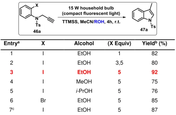
Considering TTMSS’s known properties in radical reactions, we began our investigation on the dehalogenation of substrate 46a followed by an 5-exo-dig cyclization reaction by evaluating the effect of different parameters on the reaction conditions, namely the amount of TTMSS (Table 1), solvents and halide substituents (Tables 2 and 3), and N-protecting groups (Table 4).
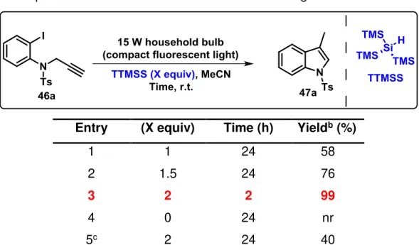
To test the feasibility of the outlined plan, the ability of TTMSS to promote the photochemical cyclization process of N-tosyl-propargyl aniline (46a) towards the
formation of indole ring system (47a) was investigated. The use of 1 equivalent of TTMSS in CH3CN at room temperature for 24 hours let to the desired product with 58%