João Gabriel Ramos Ferreira Bernardo
A contribution for data processing and
interoperability in Industry 4.0
Tese de Mestrado
Mestrado em Engenharia de Sistemas
Trabalho efetuado sob a orientação dos
Professora Doutora Leonilde Varela
Professor Doutor Luís Ferreira
DIREITOS DE AUTOR E CONDIÇÕES DE UTILIZAÇÃO DO TRABALHO POR
TERCEIROS
Este é um trabalho académico que pode ser utilizado por terceiros desde que respeitadas as regras e boas práticas internacionalmente aceites, no que concerne aos direitos de autor e direitos conexos.
Assim, o presente trabalho pode ser utilizado nos termos previstos na licença abaixo indicada. Caso o utilizador necessite de permissão para poder fazer um uso do trabalho em condições não previstas no licenciamento indicado, deverá contactar o autor, através do Repositório da Universidade do Minho.
Licença concedida aos utilizadores deste trabalho
Atribuição CC BY
A
CKNOWLEDGMENTFirst, I would like to thank professor Leonilde Varela and Engineer Joana Vinhas who made the bridge between the system engineering course and the company. Without this opportunity, the project would not be possible.
I would like to thank my advisors, professor Leonilde Varela for the continuous support and professor Luis Ferreira for sharing his knowledge with me.
My sincere gratitude and congratulations to the process engineering department of ZF Ponte de Lima for their patience and help along the process. They have the task to integrate all the company processes using not many resources.
Without the IT manufacturing team help, the code would not be completed until today. A special thanks to my mentor in-company, Diogo Silva, for the motivation and help.
Lastly, a profound thank to my brother, parents and family for encouraging me through the entire process. Without my mom and dad supports I could not be who I am today.
iv
STATEMENT OF INTEGRITY
I hereby declare having conducted this academic work with integrity. I confirm that I have not used plagiarism or any form of undue use of information or falsification of results along the process leading to its elaboration.
I further declare that I have fully acknowledged the Code of Ethical Conduct of the University of Minho.
R
ESUMOEspera-se que a Indústria 4.0 seja uma mudança significativa no crescimento das empresas. O objetivo é agrupar informações importantes de toda a cadeia de suprimentos da empresa, proporcionando uma tomada de decisão mais acertada, ao mesmo tempo que permite interações entre seres humanos e máquinas em tempo real.
Sistemas autônomos equipados com Tecnologias da Informação possibilitam a Indústria 4.0 como a Internet das Coisas (IoT), sistemas ciber-físicos (CPS) e Big Data e analytics.
A IoT coleta informações de cada peça do grande quebra-cabeça que é o processo de fabricação. Cloud Computing lida com armazenamento de toda essa informação em um só lugar. As pessoas compartilham informações em toda a empresa, na cadeia de abastecimento e níveis hierárquicos por meio da integração de sistemas. Por fim, Big Data e analytics são de inteligência que melhorarão a Indústria 4.0.
Os métodos e ferramentas da Indústria 4.0 são projetadas para aumentar a interoperabilidade entre os stakeholders. Para tornar possível essa interoperabilidade, um padrão em toda a empresa deve ser implementado.
Dois modelos de referência para a Indústria 4.0 foram estudados - RAMI 4.0 e IIRA. RAMI 4.0, a iniciativa alemã, concentra-se na digitalização industrial, enquanto IIRA, a iniciativa americana, foca no mundo da Internet das Coisas, como energia, saúde e transporte.
As duas iniciativas visam obter dados inteligentes dos processos e, ao mesmo tempo, permitir a interoperabilidade entre os sistemas. Representantes dos dois modelos de referência estão a trabalhar juntos para discutir os padrões de interface tecnológica que podem ser usados pelas empresas que entram nessa nova era.
Este estudo visa a interoperabilidade entre sistemas. Embora deva haver um modelo para orientar a empresa na Indústria 4.0, esse modelo deve ser mutável e flexível o suficiente para lidar com diferenças no processo de fabricação, como exemplo a indústria 4.0 automotiva não terá a mesma abordagem que a Indústria 4.0 de aviação.
P
ALAVRAS-C
HAVEvi
A
BSTRACTIndustry 4.0 is expected to drive a significant change in companies’ growth. The idea is to cluster important information from all the company’s supply chain, enabling valuable decision-making while permitting interactions between machines and humans in real time. Autonomous systems powered with Information Technologies are enablers of Industry 4.0 – like Internet of Things (IoT), Cyber Physical-Systems (CPS) and Big Data and analytics.
IoT gather information from every piece of the big puzzle which is the manufacturing process. Cloud Computing store all that information in one place. People share information across the company, between its supply chain and hierarchical levels through integration of systems. Finally, Big Data and analytics are of intelligence that will improve Industry 4.0.
Methods and tools in Industry 4.0 are designed to increase interoperability across industrial stakeholders. In order to make the complete process possible, standardisation must be implemented across the company.
Two reference models for Industry 4.0 were studied - RAMI 4.0 and IIRA. RAMI 4.0, a German initiative, focuses on industrial digitalization while IIRA, an American initiative, focuses on “Internet of Things” world, i.e. energy, healthcare and transportation.
The two initiatives aim to obtain intelligence data from processes while enabling interoperability among systems. Representatives from the two reference models are working together on the technological interface standards that could be used by companies joining this new era.
This study aims at the interoperability between systems. Even though there must be a model to guide the company into Industry 4.0, this model ought to be mutable and flexible enough to handle differences in manufacturing process, as an example automotive industry 4.0 will not have the same approach as aviation Industry 4.0.
K
EYWORDSC
ONTENTSAcknowledgment ... iii
Resumo ... v
Abstract ... vi
List of figures ... x
Abbreviations and Acronyms ... xi
1. Motivation and background ... 1
1.1 Objectives ... 1
1.2 Structure of the Dissertation ... 2
2. Literature Review ... 3
2.1 Historic Background ... 3
2.2 Third Industry Revolution ... 5
2.2.1 Sensors ... 5
2.2.2 Actuators ... 5
2.2.3 Programmable logic controllers (PLC) ... 5
2.2.4 Communication and OPC ... 6
2.2.5 Supervisory Control and Data Acquisition (SCADA) ... 6
2.2.6 Manufacturing Execution System (MES) ... 7
2.2.7 Enterprise Resource Planning (ERP) ... 7
2.3 Industry 4.0 (I4.0) ... 7
2.3.1 Enabling Technologies ... 9
2.3.2 Industry 4.0 implementation ... 10
2.3.3 Systems integration ... 11
2.3.4 Cyber-physical systems (CPS) ... 13
2.3.5 Reference Architecture Model of Industry 4.0 (RAMI 4.0) ... 13
2.3.6 Reference Architecture (IIRA) ... 17
2.3.7 IIRA and RAMI 4.0 interoperability ... 21
2.4 Technologies ... 24
viii
2.4.2 Structured Query Language (SQL) ... 24
2.4.3 Conceptual database design ... 25
2.4.4 Logical database design ... 25
2.4.5 Physical database design ... 26
2.4.6 Views ... 26
2.4.7 MS Office Access ... 26
2.4.8 Microsoft .NET and Microsoft .NET Framework ... 27
2.4.9 Microsoft Visual Studio .NET ... 27
2.4.10 Object Relational Mapping ... 27
2.4.11 ActiveX Data Objects, ADO.NET and Entity Framework ... 27
2.4.12 Simulation... 28
2.4.13 Knime Analytics platform ... 28
2.4.14 Power BI ... 28
3. Company Profile ... 29
3.1 ZF Group ... 29
3.2 Company Information systems ... 31
4. Problem Description ... 32
5. Proposed Improvements ... 32
5.1.1 Contribution ... 32
5.1.2 Development of the conceptual model ... 33
5.1.3 Development of the logical model ... 34
5.1.4 Development of SQL physical model ... 34
5.1.5 Integrating SQL and Visual Studio ... 35
5.1.6 Knime and Simio Analysis ... 36
5.1.7 Tools for decision-making towards Industry 4.0 – under development ... 37
6. Conclusion ... 39
6.1 Difficulties ... 39
6.2 Overview ... 39
6.3 Future works ... 40
Annex I – Data Dictionary: entities description ... 47
Annex II – Data Dictionary: relationship description ... 47
Annex III – Data Dictionary: attributes description ... 47
Annex IV – referential integrity ... 50
Annex V – SQL structure statement ... 51
Annex VI – SQL views ... 51
Annex VII – C# input class... 53
Annex VIII – C# department class ... 53
Annex IX – C# priority class ... 53
Annex X – C# localization class ... 54
Annex XI – C# issue class ... 54
Annex XII – C# project code ... 55
x
L
IST OF FIGURESFigure 1 - The four stages of the Industrial Revolution (source: Ślusarczyk, 2018) ... 4
Figure 2 - PLC (source: Alphonsus & Abdullah, 2016) ... 6
Figure 3 - The McKinsey Digital compass for Industry 4.0 (source: Mckinsey, 2016) ... 11
Figure 4 - Industry 4.0 vertical integration (source: i-SCOOP, 2019) ... 13
Figure 5 - RAMI 4.0 (source Federal Ministry for Economic Affairs and Energy, 2018) ... 14
Figure 6 – RAMI4.0 Layers basic questions ... 16
Figure 7 - IIRA constructs (source: Lin et al., 2019) ... 18
Figure 8 -IIRA viewpoints (source: Lin et al., 2019) ... 18
Figure 9 - Functional domains (source: Lin et al., 2019) ... 20
Figure 10 - Functional Domains, Crosscutting Functions and System Characteristics (source: Lin et al., 2019) ... 21
Figure 11 – Correspondences between architectures (source: Lin et al., 2018) ... 22
Figure 12 - IIRA and RAMI4.0 interoperability (source: Lin et al., 2018) ... 23
Figure 13 Occupant safety systems worldwide (adapted from ZF Friedrichshafen AG, September 2017) ... 30
Figure 14 - Million units sold in 2018 ... 30
Figure 15 - ER Diagram ... 34
Figure 16 - view for location and lines ... 35
Figure 17 - employees table ... 35
Figure 18 - entity framework ... 36
Figure 19 - simulation model ... 37
Figure 20 - simulation experience ... 37
A
BBREVIATIONS ANDA
CRONYMS CPS Cyber-Physical SystemCPPS Cyber-Physical Production System DBMS Database Management System ERP Enterprise Resource Planning
IDE Integrated Development Environment IIRA Industrial Internet Reference Architecture IIoT Industrial Internet of Things
IoT Internet of Things
MES Manufacturing Execution System
OPC-UA Open Platform Communications Unified Architecture ORM Object Relation Mapping
PLC Programmable Logic Controllers
RAMI 4.0 Reference Architecture Model Industry 4.0 RFID Radio Frequency Identification
SCADA Supervisory Control and Data Acquisition SOA Service Oriented Architecture
SQL Structured Query Language GUI Graphical User Interface
1. M
OTIVATION AND BACKGROUNDThe present dissertation emerged under the scope of the master’s in systems engineering. This project was developed at ZF Passive Safety Division in the process engineering department of Ponte de Lima.
This division is growing at a fast pace entailing huge data processing. The products sold to the final client are assembled from the manufacturing process pass through a rigid process of data traceability. Those data are stored in Microsoft SQL Server databases and tables.
Handling difficulties in information management have been an important task to any company’s grow.
The difficulties were perceived and motivated this research. In this project, the main purpose is the integration of the in-company information and with this organized information, improve decision-making.
Global competition is becoming fiercer every day. Countries in Europe, Asia and the U.S.A have been recognizing the trend to deploy new digital technologies in the manufacturing Industry. This emphasizes that the fourth industrial revolution is close.
In Germany, “Industrie 4.0” represents a revolution in Information and Communication Technologies (ICT) where Internet of Things, Cyber-Physical Systems, Industrial Information and Integration are crucial to enable a transformation on how to optimize work and improve decision-making.
Nowadays organizations aim to manage their business, clients and operations using data analysis provided from different sources as sensors, web applications, social media and wearable devices. According to Russom (2011), these analysis and sources are called “Big Data”.
The organizations that holds more knowledge and meet their client expectations have more opportunities to grow in the market. However, organizations find it difficult to storage and process data.
1.1 Objectives
1. Literature review of Industry 4.0. This review will gather the necessary theory concepts that will be the base for the architecture implementation – from the history context of industrial revolutions to today’s disruption, the study of reference models for Industry 4.0 and the importance of standards using relational databases.
2. The actual industrial scenario for the case studied.
3. Understand how pieces of technology fit together to form a business solution: o How database tables, from different schemas, connect with each other; o How database tables are populated by the user using a Graphical User
Interface (GUI);
o How to create the GUI via programming in C# and connect with databases; o Gather information for decision-making.
1.2 Structure of the Dissertation
This document is divided into 6 chapters. The first chapter comprises of an introduction, motivation and objectives of this document.
The following chapter contains a literature review of Industry 4.0: the historic background, how can information created in the shop floor can reach the enterprise managers for decision-making, the enabling technologies, horizontal, vertical and end-to-end integration, Cyber-Physical Systems, reference architectures (RAMI 4.0 and IIRA) and the interoperability between these architectures.
This second chapter also contains a literature review of technologies that motivated this research: structure query language (SQL), database conceptual, logical and physical designs, database views, Microsoft office Access, .NET and .NET Framework, Visual Studio, Object Relational Mapping (ORM), ActiveX Data Objects, Entity Framework, Simulation and Knime Analytics platform.
Chapter 3 there are information about the company that provided the tools and knowledge that enabled this project. This chapter describes the information system the plant has. In chapter 4, the problem description is introduced and, in the following chapter, the improvements to avoid ambiguity are proposed.
The last chapter refer to the difficulties observed during the literature review of Industry 4.0 and the overview of this project while integrating information.
2. L
ITERATURER
EVIEWAs stated by Mulrow (2014), a systematicliterature review has the following benefits:
1. Reduces the quantity of information into small pieces that are more likely to be understood by the reader;
2. Integrates pertinent pieces of information for decision-making;
3. It reduces the cost of creating a new research and can avoid survey of an already explored path;
4. Through multiple reviews it is possible to develop a generalization on the topic; 5. Evaluates the consistency of different variables;
6. Explains data inconsistencies and their correlation; 7. With more statically data, map future directions; 8. Qualitative analysis allows increased precision; 9. Improved reflection of reality.
The purpose of this topic is to show a summarized review of the actual industrial revolution, how we achieved today’s state and how to achieve Industry 4.0.
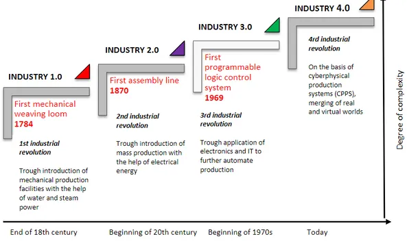
2.1 Historic Background
It is important to understand how production evolved to the current scenario. According to Sabo (2015), the first industrial revolution started in 1760 and lasted up to 1830, where the mechanization changed the manufacturing process from hand production to machine production. These machines were powered by steam. Coal started to replace wood.
Machinery was powered by electricity in the second revolution, which took place between 1840 and 1870. Opportunities aroused to deliver huge amounts of goods from one place to another with the help of railroads and the capability of machinery combined with electric power led to the line production and mass production.
Between 1950 and 1970 the digital revolution took place. This was the third revolution, where digital and communication technologies were the beginning of the Information Age. Automation of the labour and the use of Information Technologies (ITs) characterized this disruption.
Nowadays any enterprise can gather great amount of information. As an example, it can acquire information from all their customers, their needs and how they manage their social life. This digital era is enabling another industrial revolution. In Germany, this revolution is called “Industrie 4.0”.
Figure 1 summarizes the industrial revolutions:
Figure 1 - The four stages of the Industrial Revolution (source: Ślusarczyk, 2018)
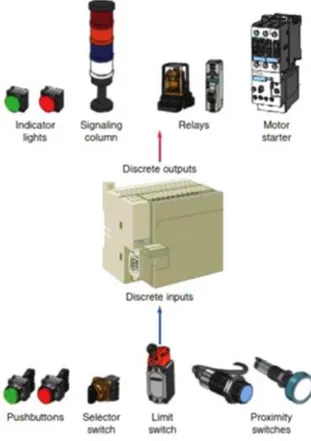
It is important to understand how programmable logic controllers, from the third industrial revolution control, works as they are a crucial technology to achieve industry 4.0.
2.2 Third Industry Revolution
2.2.1 Sensors
As stated by Macedo (2017), sensors in general transmits an electric signal from a received impulse. Their goal is to send a signal to the command center (that can be a programmable logic controller or other industrial computer).
2.2.2 Actuators
A piece of hardware dispositive that converts a signal from a controller to a physical magnitude. Actuators are responsible for actuation of mechanical systems, on summary actuators can convert electrical energy into mechanical energy (e.g., compressed air in pneumatics and oil in hydraulics) (Macedo, 2017).
2.2.3 Programmable logic controllers (PLC)
According to Alphonsus & Abdullah (2016) the first PLC came in the late 1960s in automotive industry. The authors state that PLC is the central component and are determinant in any autonomous system. The basic blocks are:
• Rack assembly; • Power supply;
• Programming device; • Input/Output sector; • Central processing unit.
According to Macedo (2017) the PLC receive data from sensors, command buttons and other inputs, execute instructions from a program saved on his memory, and builds a system response by modifying the state of the outputs where all the actuators are connected. Figure 2 exhibit sensors, PLC and actuators:
Figure 2 - PLC (source: Alphonsus & Abdullah, 2016)
2.2.4 Communication and OPC
Open Platform Communications (OPC) arrive two decades after the first PLC. OPC foundation defines standards
between communication from controllers regardless of the communication protocols used by their manufacturers (Macedo, 2017). According to the author, the primary goal is to transfer real data across PLCs, distributed control systems, Supervisory Control and Data Acquisition (SCADA), Human Machine Interface (HMI) and other production applications. OPC data access depends on the technology DCOM (distributed component object model) with security limitations and closed to Windows platform. Those problems led the OPC Foundation to create a new protocol in 2006: OPC unified architecture (OPC UA), that is more flexible and adaptable (Macedo, 2017).
2.2.5 Supervisory Control and Data Acquisition (SCADA)
Supervisory Control and Data Acquisition (SCADA) are mainly associated with critical infrastructures that request high level of support in real time such as chemical processes, railways, water treatment and distribution and power plants (Macedo, 2017).
2.2.6 Manufacturing Execution System (MES)
According to Huang, Mohanty, Ashfahani, & Pratama (2018) a manufacturing execution system (MES) “is used to monitor the information flow from manufacturing objects on the manufacturing shop floor”. Manufacturing objects are work in process, workstation, tools and employees.
2.2.7 Enterprise Resource Planning (ERP)
According to Slack, Chamber, & Johnston (2009), ERP is an information system that integrate all enterprise information from different functions (and that information most of the times comes in high volumes), necessary to the planning and controlling of the operations. This integration occurs in a common database where all information can be shared.
As stated by the authors, this control informs when and where the activity must occur, who is responsible and how much capacity will be needed to complete the task and so on.
2.3 Industry 4.0 (I4.0)
Germany has global leadership in the manufacturing sector (Kagermann, Wahlster, & Helbig, 2013). Global competition is becoming more aggressive every year. Not only Germany is taking measures to mitigate this impact but also the U.S.A is avoiding deindustrialization with initiatives to promote advanced manufacturing (Fiesp, 2017).
The term “Industrie 4.0” (Industry 4.0) proposed in Hannover Fair in 2011 was announced in 2013 as a German strategic action to implement technologies mainly Cloud Computing, Internet of Things (IoT) and cyber-physical systems (CPS) in a way to revolutionize the manufacturing industry (Xu et al., 2018). As stated by the authors, Industry 4.0 collects information from sensors, artificial intelligence, data analytics to improve manufacturing work in real-time.
Industry 4.0 planning is to achieve all these three major integrations, with addition to hardware, software, data and information integration (Xu et al., 2018).
The term Industry 4.0 described in 2016 by Smit, Kreutzer, Moeller, & Carlberg is: “the organization of production processes based on technology and devices autonomously communicating with each other along the value chain: a model of the ‘smart’ factory of the future where computer-driven systems monitor physical processes, create a virtual copy of
the physical world and make decentralized decisions based on self-organization mechanisms”. With the increasing of digital manufacturing, physical objects are integrated into the information network.
As stated by Smit et al. (2016) for the success of Industry 4.0 there must be a standardization of systems, platforms, protocols, flexibility to adjust to new business models, security, research and investment, and a common legal framework to support the dissemination of Industry 4.0.
Wortmann, Combemale, & Barais (2017) describes Industry 4.0 as a “vision of manufacturing in which smart, interconnected production systems optimize the complete value-added chain to reduce cost and time-to-market”.
Stephen (2018) affirms that Internet of Things (IoT) is expected to generate “$1.2 to $3.7 trillion value globally by 2025, in four primary forms: 1) operational efficiency, 2) predictive and preventive maintenance, 3) supply chain management, and 4) inventories and logistics. According to a survey from Mckinsey in 2016, most Industry 4.0 players (United States, Germany and Japan) expect cost and revenue increases of 10 to 15 percent.
According to Ślusarczyk (2018), the 4th Industrial Revolution is happening globally and concurrently. In Europe Fiesp (2017) presents the main initiatives of Industry 4.0 across the globe: UK (High Value Manufacturing, Innovative UK), Germany (Smart Service World, Autonomik Fur Industrie 4.0, Industrie 4.0), France (Usine du Future, The Nouvelle France Industrielle), Sweden (Produktion 2030), Italy (Fabbrica Intelligente), Belgium (Made Different), Netherlands (Smart Industry), Spain (Industria Conectada 4.0), Portugal (Produtech), Austria (Produktion der Zukunft), Poland (INNOMOTO, INNOLOT), Finland (Finnish Metals and Engineering Competence Cluster, Industry Internet Business Revolution, IoT Pilot Factory).
The US incentives their automatization with a more sustainable and digital industry (e.g. Advanced Manufacturing Partnership, Industrial Internet Consortium, National Robotics Initiative). In China the term “made in China 2025” is the Chinese plan to make their manufacturing industry a global leader and in 2015 Japan launched the Industry Value Chain forum to discuss Industry 4.0 and robotics.
Rodič (2017) states that today, the main enabling technologies and development tendencies in Industry 4.0 are:
• Horizontal and vertical system integration; • The Internet of Things;
• The Cloud;
• Big Data and analytics;
• Green Information Technology; • Augmented reality;
• Additive manufacturing (3D printing); • Simulation modelling;
• Autonomous robots; • Cybersecurity.
In summary, Industry 4.0 is the manufacturing process in an interoperability, adaptability, optimized and service-oriented approaches correlated with algorithms, big data, and high technologies.
2.3.1 Enabling Technologies
The main technologies that permits the implementation of Industry 4.0 are Internet of Things (IoT), Cloud Computing, Big data storage and analytics (Sony, 2018).
At the beginning of the Internet of Things, objects were connected using radio-frequency identification (RFID) technology. This enabled tracking in real-time objects identified with unique tags that were connected to the Internet. RFID is the keystone to IoT (Sony, 2018). RFID made possible today’s use of the IoT, aggregating this technology to global positioning systems, actuators, sensors operating through Wi-Fi, Bluetooth, Near Field Communication (NFC) or cellular networks (Xu, Xu, & Li, 2018).
According to Vermesan & Friess (2014), IoT is the new revolution of the Internet. The goal of IoT is to enable connection with anyone, anytime and anywhere using any path/network. In 2011 the number of Internet-connected devices (ICD) surpassed the population. By 2020 ICD are expected to be a number between 26 billion and 50 billion (Vermesan & Friess, 2014) creating massive volume of data to be analysed.
This large volume of data lead to the term “Cloud Computing”. This technology relies mainly on huge volume (Xu et al., 2018).
For instance, the design of a new product can be developed by engineers and fabricators in virtual community. Those individuals may not be in the same physical place (e.g., in-company) but the information can be shared.
The integration of IoT in Cloud platforms helps creating new services that would not be obvious without this high level of connectivity and analytical intelligence. The collection of a huge amount of data, results in the Big Data storage (Frank A G, Dalenogare L S, & Ayala N F, 2019).
According to Grable & Lyons (2018) the term Big Data means a large amount of information that requires a more robust data process than traditional methods. This complex data analysis may provide more precise insights showing patterns that could not be realized.
Together with analytics (like data mining and machine learning) it is considered one of the most important business drivers for Industry 4.0(Grable & Lyons, 2018).
Wortmann, Combemale, & Barais (2017) affirm that according to these disruptions, Industry 4.0 design principles are:
• Interoperability: connect people, production, devices and sensors;
• Information simplicity and interconnection: collect data from sensors, reduce or even eliminate data redundancy;
• Technical support: provide the right abstraction to understand the complexity of Industry 4.0;
• Decentralized decision making: enable self-sufficient systems.
2.3.2 Industry 4.0 implementation
McKinsey survey (2016) sustains that some manufacturers are struggling to implement Industry 4.0, as it is not clear to them what Industry 4.0 really requires. One concern of these manufacturers is the lack of courage to push though radical transformation.
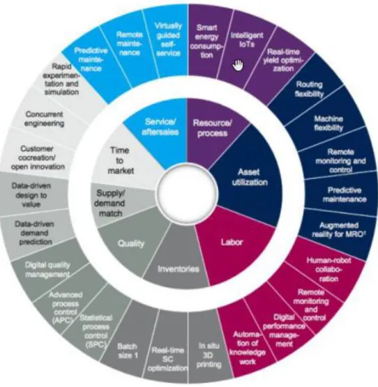
Figure 3 - The McKinsey Digital compass for Industry 4.0 (source: Mckinsey, 2016)
One of McKinsey’s conclusion for capturing value from Industry 4.0 is that manufacturers are achieving most progress when they focus on a limited number of Industry 4.0 applications and not all of them.
As stated by Fred Schulemann, Head of Digital Production at Audi AG: “We are aiming at an enormous progress in efficiency and speed particularly in engineering, controlling, administration, and decision making. But this value will only be unlocked if we manage to integrate data across the entire product lifecycle”.
The World Economic Forum in 2015 (WEF, 2015) reported that 65% of companies in Europe and North America are finding it difficult to implement industrial digitalization due to the lack of interoperability or standards.
KPMG survey from 2017 (Gates & Bremicker, 2017) states that one key driver for manufacturers to implement Industry 4.0, is that the enterprise must plan ahead.
Sony (2018) declare that Industry 4.0 is possible using three kinds of integration:
1 Horizontal integration: collaboration between organizations in the value chain. With the use of digitalization, a new synergy for all the stakeholders is created. As stated by Xu et al (2018), horizontal integration handles several Information Technology (IT) systems used in different moments of the manufacturing.
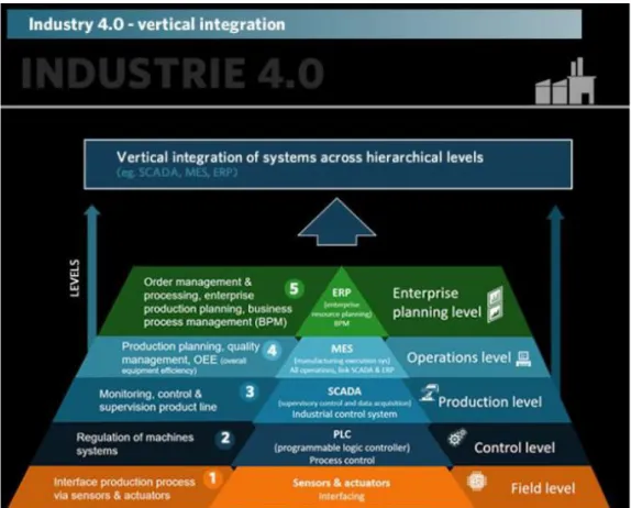
2 Vertical integration: integration of several hierarchical systems within the organization are connected to the Enterprise Resource Planning (ERP) system. Xu et al. (2018) affirm that this integration work with various IT systems at different hierarchical levels. The different hierarchical levels are: shop floor, control, production and operations and enterprise planning.
For the shop floor management, there are sensors and actuators. To manufacturing controlling there are programmable logic controllers (PLCs). At the next level, there is a Supervisory Control and Data Acquisition (SCADA) System. A manufacturing execution system (MES) will be for production planning and quality management. On top there is an Enterprise Resource Planning (ERP) to integrate all data from an organization into one system (i-SCOOP, 2019). The vertical integration is presented in Figure 4.
Figure 4 - Industry 4.0 vertical integration (source: i-SCOOP, 2019)
3 End-to-end engineering integration: According to Xu et al. (2018) this process aggregate digital and real world, information from the entire value chain, different companies, and customer requirements. According to Adolphs et al. (2015) end-to-end engineering means that technical, commercial and administrative data generated in the means of production are accessible at all times within the entire supply chain.
2.3.4 Cyber-physical systems (CPS)
“CPS are engineered systems that are built from, and depend upon the seamless integration of computational algorithms and physical components” (Xu et al., 2018).
According to Rodič (2017) with the use of CPS it will be feasible to coordinate the intelligence network of all subsystems in a central computer, making it possible to work with rising independence.
As reported by the Federal Ministry for Economic Affairs and Energy in 2016, Germany vision is to encourage more businesses to get involved in Industry 4.0. To make it a reality, five work groups were created:
1) Reference Architectures, Standards and Norms; 2) Research and Innovation;
3) Security and Networked Systems; 4) Legal Framework;
5) Work, Education and Training.
The first group main development is the reference architecture model of industrie 4.0 (RAMI 4.0), certified and published as DIN (Deutsches Institut für Normung, German Institute for Standardization) specification 91345.
RAMI “enables the identification of relevant standards” and if no standard is used, RAMI helps to identify gaps in the missing architecture.
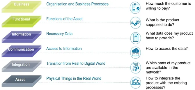
A common vocabulary between machines communication is the basic requirement to ensure interoperability in Industry 4.0 (Federal Ministry for Economic Affairs and Energy, 2016). RAMI 4.0 is a three-dimensional map (Figure 5) showing the most important aspects of industrie 4.0 (Federal Ministry for Economic Affairs and Energy, 2018):
1. Layers:
As reported by the Federal Ministry for Economic Affairs and Energy (2018) “this correspond to IT thinking where complex projects are split into clusters of manageable parts”:
1.1. Business layer: represents the business vision, models, economic market structures, organizational policies (legal frameworks) and provides a link between different business processes. It is the bridge to the functional layer.
1.2. Functional layer: permits changes of information between real and virtual worlds. An Enterprise Resource Planning (ERP) system typically will be located under this layer as well as rules and decision-making logic. It also permits access to horizontal integration.
1.3. Information layer: Ensures data integrity, how data is utilized and changed between processes, and obtains new and higher quality data. In this layer, we can have databases about the company’s products or data from the equipment used in operations.
1.4. Communication layer: Describes protocols standards, permitting communication between Programmable Logic Controllers (PLCs) in the shop floor and Manufacturing Execution Systems (MES) or ERP.
1.5. Integration Layer: Allow the integration between virtual world and real world. Contains elements connected with IT, such as RFID, sensors, routers, terminals, QR-Codes with the goal to convey the created content to asset layer.
1.6. Asset layer: Represents the real world, like machines and human beings. Humans are connected to the virtual world via the Integration Layer.
In Figure 6 platform Industrie 4.0 (“RAMI4.0 - a reference framework for digitalisation,” 2018) provide basic questions about the business idea:
Figure 6 – RAMI4.0 Layers basic questions 2. Life Cycle and Value Stream:
Relationships and links for the product, machines, and factories life-cycles are designed in this dimension. The life-cycle differs between type and instance. Type is the initial idea, generating a prototype that after testing and validation are produced and become an instance. The instance has a unique serial number. These are sold to final customers. If the product needs an improvement, the product goes back to type stage (Federal Ministry for Economic Affairs and Energy, 2018).
3. Hierarchy levels
It represents the different functionalities within factories or facilities. This dimension describes the functional classification of various situations of Industry 4.0 (Federal Ministry for Economic Affairs and Energy, 2018).
Products are the electronic devices (e.g. machines). Field device are sensors to gather data. Control devices are the main component of the machine, like PLCs. Station analyse data in real time to monitor the system. Work centers may control the production state, requiring new components and restoring the production goals. Enterprise is the business management like planning and control, statistics, marketing, sales. Connected world is the communication between stakeholders, making it possible the information sharing (Carvalho, 2018).
How much the customer is willing to pay?
What is the product supposed to do?
What data does my product have to provide?
How to access the data?
Which parts of my product are available in the network?
How to integrate the product with the existing processes?
IEC stands for International Electrotechnical Commission and provides norms used in Industry. IEC 62264 are for enterprise IT and control systems. IEC 62890 are for life-cycle management and IEC 61512 are for batch control (Gotze, 2016).
Lydon states that a service-oriented architecture (SOA) is defined in RAMI 4.0 where application components provide services to the other components through a communication protocol over a network. Xu et al. (2018) states that OPC-UA (Ole for Process Control Unified Architecture) protocols establish a communication between Industrie 4.0 layers. OPC-UA supports service-oriented architecture (SOA) that integrate platforms, improve flexibility and reduce the gap between enterprise architecture and information and communication technology (ICT) infrastructure redesign.
2.3.6 Reference Architecture (IIRA)
RAMI 4.0 is not the only standard for Industry 4.0. Industrial Internet Reference Architecture (IIRA) from Industrial Internet Consortium (IIC) was designed by AT&T, Cisco, GE, IBM and Intel in march 2014 with the goal to connect and integrate people, processes and data (Gotze, 2016).
The Industrial Internet Architecture Framework “identify and classify stakeholder concerns into appropriate categories” (Lin et al., 2019).
According to IIC, at IIRA core are viewpoints that specify system concerns. Concern indicate problems related to the system. Model kinds are modelling constructs to resolve those concerns. Architecture views and architecture models can be considered as the representation of architecture.
Figure 7 - IIRA constructs (source: Lin et al., 2019)
According to IIC, views are the starting point for concrete architecture and may be replaced by better ones according to the needs of the IIoT (Industrial IoT) system at hand.
The four viewpoints defined by IIRA fitting IIoT concerns are (Figure 8):
Figure 8 -IIRA viewpoints (source: Lin et al., 2019)
1. Business: Identify stakeholders and their business vision, values and objectives in setting up an IIoT system and how IIoT could improve the enterprise activities. Values and objectives emerge from this vision. This viewpoint is about enterprise motivation and who benefits from IoT system.
2. Usage: This viewpoint focuses on how to address the concerns described in the business viewpoint. These concepts are developed to coordinate activities of the system:
2.1. Tasks: Basic unit of work connected to operation, data transfer or action. The role (set of capacities assumed by an entity to do some tasks required by an activity), functional map and implementation map are concepts of a task.
2.2. Activity: Coordinate different tasks. An activity can be executed recursively having four elements: trigger (how the activity will be initiated), workflow (sequential, parallel, conditional, iterative organization of tasks), effect (the phase of the IIoT system after successful completion of an activity) and constraints (characteristics that must be maintained like integrity and reliability).
2.3. Party: Agent, human or robot that have interest in the execution of a task.
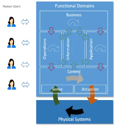
3. Functional: How the IIoT system will interact and interfaces between external environment and other systems to support the usages and activities of the overall system. A typical IIoT system is decomposed into five functional domains:
3.1.1. Control Domain: Is the domain for implementing industrial control system. It reads data that comes from other systems, determine component rules and control those rules using actuators. An example is the control unit in autonomous vehicle.
3.1.2. Operations Domain: Management and operation of the control domain with the goal to optimize activities and generate value for stakeholders.
3.1.3. Information Domain: Manages and process data to acquire high-level intelligence about the overall system.
3.1.4. Application Domain: Is the domain for implementing logic.
3.1.5. Business Domain: Functions for integrating information across business systems and applications to achieve business objectives. Examples are ERP, Customer Relationship Management (CRM), Manufacturing Execution System (MES), Human Resource Management (HRM) and Product Life Management (PLM).
Figure 9 - Functional domains (source: Lin et al., 2019)
4. Implementation: Integration is the key topic on this viewpoint. It presents the communication schemes, technologies, lifecycles to coordinate activities (usage viewpoint) and supportive of system capabilities (business viewpoint)., i.e. technical representation.
IIRA uses ISO/IEC/IEEE 42010:2011 (system and software engineering-architecture description) standard.
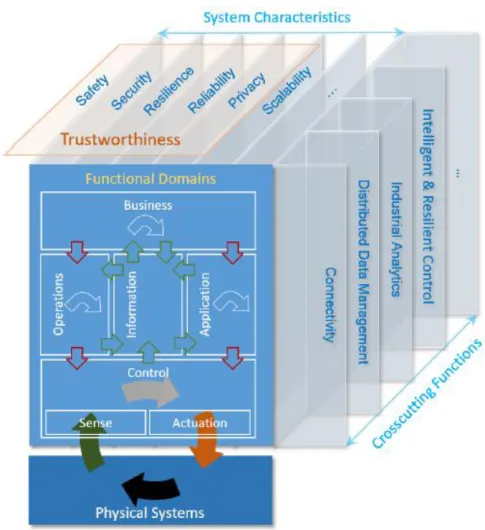
Additional functions must exist to enable a non-generic IIoT. These functions must be available across many of system functional, that are called crosscutting functions, like connectivity or data management and new characteristics will emerge when the system is integrated. Figure 10 represents the integration of the three aspects of industrial internet reference architecture:
Figure 10 - Functional Domains, Crosscutting Functions and System Characteristics (source: Lin et al., 2019)
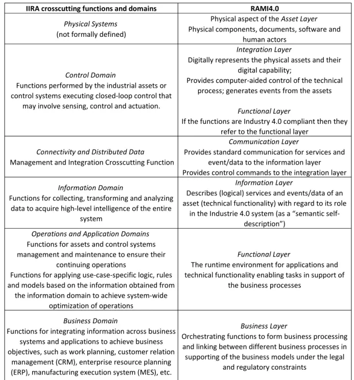
2.3.7 IIRA and RAMI 4.0 interoperability
(Fiesp, 2017) states that representatives of Industrie 4.0 in Germany are meeting with representatives of Industrial Internet Consortium from U.S.A to discuss the technological interface standards.
In Germany and the U.S.A there have been an increase on creation and usage of testbeds to simulate productive systems and evaluate the reference architecture (Fiesp, 2017).
As reported by the Federal Ministry for Economic Affairs and Energy at the beginning of march 2016, Industrie 4.0 started to cooperate more closely with IIC. The former initiative focuses on industrial digitalization while the latter focus on Internet of Things world, like energy, healthcare and transportation, stressing cross-industry communication and interoperability. Both initiatives complement each other as they both aim at obtaining intelligence data from processes while enabling interoperability among systems.
IIRA and RAMI4.0 have different emphasis in scope and depth, but these different perspectives can complement each other in addressing challenges into digitalization. “For
example, industrial analytics, an idea that is emphasized in IIRA would be beneficial for building intelligent Industrie 4.0 systems” (Lin et al., 2018).
Comparison between IIRA and RAMI 4.0 are done in Figure 11.
Figure 11 – Correspondences between architectures (source: Lin et al., 2018)
Interoperability can be defined as “the ability of two or more systems or components to exchange information and to use this exchanged information” (Blanc-Serrier, Ducq, & Vallespir, 2018).
Figure 12 represents the interoperability between the two references architectures studied:
IIRA crosscutting functions and domains RAMI4.0
Physical Systems
(not formally defined)
Physical aspect of the Asset Layer Physical components, documents, software and
human actors
Control Domain
Functions performed by the industrial assets or control systems executing closed-loop control that
may involve sensing, control and actuation.
Integration Layer
Digitally represents the physical assets and their digital capability;
Provides computer-aided control of the technical process; generates events from the assets
Functional Layer
If the functions are Industry 4.0 compliant then they refer to the functional layer
Connectivity and Distributed Data
Management and Integration Crosscutting Function
Communication Layer
Provides standard communication for services and event/data to the information layer
Provides control commands to the integration layer
Information Domain
Functions for collecting, transforming and analyzing data to acquire high-level intelligence of the entire
system
Information Layer
Describes (logical) services and events/data of an asset (technical functionality) with regard to its role
in the Industrie 4.0 system (as a “semantic self-description”)
Operations and Application Domains
Functions for assets and control systems management and maintenance to ensure their
continuing operations
Functions for applying use-case-specific logic, rules and models based on the information obtained from
the information domain to achieve system-wide optimization of operations
Functional Layer
The runtime environment for applications and technical functionality enabling tasks in support of
the business processes
Business Domain
Functions for integrating information across business systems and applications to achieve business objectives, such as work planning, customer relation
management (CRM), enterprise resource planning (ERP), manufacturing execution system (MES), etc.
Business Layer
Orchestrating functions to form business processing and linking between different business processes in supporting of the business models under the legal
2.4 Technologies
This topic presents the importance of the tools that made possible the contribution. All tools were developed in Windows platform.
2.4.1 Database
This technology can aid an optimized approach where data consistency will enable a readily data analysis to support decision-making.
Database architecture methodology assist the planning, management and control, modelling the base requirements in a standard (Connolly & Begg, 2005).
The relational database is being used for more than 30 years all over the world. This kind of database changed significantly the way the productivity of organizations. The development of this technology created a more intuitive use. Therefore, the database is not a department property, but a resource shared thought the enterprise (Connolly & Begg, 2005).
Cristian (2017) affirms that the database involves share of data and applications and present countless benefits, like:
• Reduce and even eliminate data redundancy using data integrity, thus avoiding copies of the same data. With this minimization, data consistency may be maximized.
• Security measures to avoid data manipulation from people without authorization. • The database allow access by multiple users at the same time.
The database management system (DBMS) is a software that allow the creation, maintenance, control and access to databases. DBMS interacts with applications created by the user that can be written in procedural language (that describes how to do something) coming from the third generation of programming language (3GL) like C, C++, C#, Java, Visual Basic, COBOL, Fortran, Ada and Pascal or though the integration of programming languages from the fourth generation (4GL) (that describes what shall be done) with 3GL like the structure query language (Connolly & Begg, 2005).
Using this integration there is a segregation between data structure (where the data is stored) and applications (Connolly & Begg, 2005).
According to Connolly & Begg (2005), SQL is a language developed to use the relationships between tables and transform inputs in outputs using two components:
• Data definition language – DDL to define the database structure and control the information;
• Data manipulation language – DML to retrieve and update data.
SQL is a global standard to define and manipulate relational databases (Connolly & Begg, 2005).
2.4.3 Conceptual database design
The conceptual database design is independent of all implementation details such as: hardware, software, applications and programming languages (Connolly & Begg, 2005). According to Connolly & Begg (2005) a conceptual model comprises:
• Entity types;
• Relationship types – using entity-relationship modelling;
• Attributes and their domains: a user can define the meaning and sources of the values that attributes can hold;
• Primary and alternate keys: primary key identifies rows uniquely within the relation; • Integrity constraints: which ensures that the data is accurate, for example: no primary
key can be null (cannot have an unknown value).
Entity-relationship model grant data integrity and their adequate usage to solve a problem from the company. It creates a model free of ambiguities and avoiding the differentiated understandability between architects, programmers and final users (Connolly & Begg, 2005). Data dictionary is produced thought out the development of the model. This dictionary identify entities, relationship and attributes description (Connolly & Begg, 2005).
2.4.4 Logical database design
The logical database design phase maps the conceptual model onto a logical model. The logical model is influenced by the data model (for example, relational model) but is independent of a particular DBMS and other physical considerations (Connolly & Begg, 2005).
According to the authors, relational databases have certain amount of data redundancy. This redundancy is in the form of a primary key from table A, acting as foreign key in table B, to enable modelling relationships.
Also stated by the authors, the derived structures from the conceptual model relationships, are identified in the logical model:
• One-to-many (1, N) relationship: parent entity must be identified as well as child entity. To represent the relationship using a foreign key, the primary key from the parent entity will be a foreign key in the child entity.
Connolly & Begg (2005) affirms that integrity constraints are represented in logical model. These actions can be performed in the child entity if a value from its parent entity is modified:
• NO ACTION is to prevent the update or deletion,
• CASCADE is to automatically update or delete any reference child row when parent row is deleted,
• SET NULL command automatically set a foreign key to null.
2.4.5 Physical database design
The physical database design is tailored to a specific DBMS. There is feedback between physical and logical design as the decisions from the physical model can alter the logic behind the database (Connolly & Begg, 2005).
SQL enable multiple users input at the same time (Connolly & Begg, 2005).
2.4.6 Views
The view is a virtual relation that does not exist in the current database, but can produce a new table with useful information (Connolly & Begg, 2005).
They are dynamic, implying that changes made in the base data table will be updated automatically in the view (Connolly & Begg, 2005).
2.4.7 MS Office Access
MS Office Access or MS Access is used for relational DBMS for Microsoft Windows environment. It provides a Graphical User Interface (GUI) to create tables, queries, forms, reports and customized applications using macro in Visual Basic for Applications (VBA)
language, it also provides a “wizard” to simplify the process for building applications (Connolly & Begg, 2005).
2.4.8 Microsoft .NET and Microsoft .NET Framework
Microsoft .NET is the current evolution in Microsoft’s Web solution strategy. Microsoft .NET have various tools, services and technologies such as Windows Server, business processes with xml, application center, mobile server, object-relational database management system and Microsoft Visual Studio .NET (Connolly & Begg, 2005).
According to the authors, Microsoft .NET Framework, in addition to .NET, has two main components that are:
• Common Runtime Language (CRL): loads, executes and manages codes like C#, C++, F#, J#, Java, Visual Basic. In CRL one language can call another language, inherit and modify objects from another language.
• .NET Framework Class Libraries: is a collection of interfaces, types and classes that integrate with CRL providing standards. The three main components are: windows forms, APS.NET (to support Web development) and ADO.NET.
2.4.9 Microsoft Visual Studio .NET
Microsoft Visual Studio .NET is an integrated suite of application development tools such as J#, C#, C++) (Connolly & Begg, 2005). This integrated development environment (IDE) includes many aspects of software development such as compilers, code completion tools, graphical designers(visual-studio-ide @ docs.microsoft.com, 2019).
2.4.10 Object Relational Mapping
Object relational mapping is a technique that abstracts the communication between two different programming paradigms like, object-oriented models and relational databases Various technologies were offered to handle this gap between object-oriented and relational databases, like Entity Framework from Microsoft (Zimányi, E., Jallow, B., Kashef, 2018).
2.4.11 ActiveX Data Objects, ADO.NET and Entity Framework
ActiveX Data Objects (ADO) is a programming tool for database connection (Connolly & Begg, 2005).
In ADO just one request to a database can be made using a single connection. On the other hand, ADO.NET that is designed by .NET framework can request multiple transactions using a single connection (ado-difference @ net-informations.com).
Entity framework is an open source ORM framework for ADO.NET which simplifies mapping between objects to columns of relational database (Tannock, 2016).
As referred by Tannock (2016), entity framework let developers focus on the business domain. The application cannot be limited by what the database is able to do.
2.4.12 Simulation
For simulation, it was used the software Simio. According to Vik, Dias, Pereira, & Oliveira (2012) Simio supports:
• 3D animation;
• Importing data from excel worksheets;
• Writing own logic functions in languages like C++ and Visual Basic; • Creating own libraries and objects.
2.4.13 Knime Analytics platform
For workflow, it was used the Knime Analytics platform (Konstanz Information Miner). This environment allows easy visual assembly, dynamic data analysis and data cleaning. It is suited to process files in csv, xls, xlsx, xml, url and relational databases (eg., SQL, MySQL, Oracle) (Feltrin, 2015).
2.4.14 Power BI
Power BI converts all data that comes from reports, worksheets, charts and emails into charts and graphs that are more meaningful to the reader (power bi @ docs.microsoft.com, 2019).
3. C
OMPANYP
ROFILE3.1 ZF Group
The following topic presents the company profile where this master thesis was developed. In the year 2000 was founded Safelife, a bag plant part of Dalphimetal Group. In May of the same year, in Vila Nova de Cerveira started the production, research and development activities. In November occurred the delivery of the first bag to the group PSA (known as PSA Peugeot Citroën from 1991 to 2016).
In January 2001 started the construction of the facility at Industrial area in Gemieira, Ponte de Lima. In October, the production was transferred to new facilities in Ponte de Lima.
In January 2004 was founded Safebag (airbags modules assembly plant) and in the same month was acquired a building in Fornelos, Ponte de Lima. In April 2004 started the production and delivery of the first airbag to Renault.
In October 2005 Dalphimetal group was acquired by TRW Automotive. In February 2008, Safe Life and Safebag lines were reorganized by products and were integrated as Ponte de Lima Plant.
In May 2015 TRW Automotive was acquired by ZF Friedrichshafen AG. Ponte de Lima plant integrated the ZF Active and Passive safety technologies division.
ZF Group have seven divisions:
1) Car Powertrain: Manual, automatic and dual clutch transmissions, axle drivers and powertrain modules;
2) Car Chassis Technology: Chassis systems, chassis components and suspension technology;
3) Commercial Vehicle Technology: Truck and Van driveline technologies, axle and transmission systems for buses and coaches and steering systems;
4) Industrial Technology: Off-Highway systems, industrial drives, marine and special driveline technology, test systems, aviation and wind power technologies;
5) E-Mobility: Electronic systems, electric traction drive and system house;
6) ZF Aftermarket: Independent aftermarket, original equipment service / specific original equipment, manufacturing, services and friction materials group;
7) Active & Passive Safety Technology: braking systems, steering systems, occupant safety systems, electronics and body control systems.
Figure 13 shows the worldwide ZF presence for occupant safety systems:
Figure 13 Occupant safety systems worldwide (adapted from ZF Friedrichshafen AG, September 2017)
In 2018, Safebag delivered approximately 14 million airbag modules. The clients were: PSA, Seat-Volkswagen, GM, Renault-Nissan, Volvo, Ford, Hyundai, Fiat and Jaguar. Figure 14 shows millions of units sold in 2018 among five airbags modules:
Figure 14 - Million units sold in 2018
According to Fernandes (2018) in 2017 ZF had a revenue of 36.4 billion Euros and Safebag had a revenue, at the same year, of 192 million Euros.
Engineering Centers & Support Manufacturing Facilities Facility Type Canada Midland Mexico Chihuahua (2) La Laguna Reynosa USA Mesa, Arizona Washington/Romeo, MI Brazil Limeira Germany Alfdorf Aschaffenburg Aschau Laage France Paris Italy Moncalieri Bricherasio Portugal Vila Nova Ponte de Lima (2) Spain Porriño Valladolid Vigo Czech Republic Stara Boleslav Poland Czestochowa (2) Romania Timisoara Roman Tunisia Ben Arous South Africa Atlantis India RTSSL Chennai TSSW Pune TSSW Gurgaon China Anting Shanghai TFASS Changchun TFASS Chengdu TFASS Foshan Wuhan Xian Zhangjiagang Korea TASS Seoul Thailand TSST Rayong Japan Yokohama
3.2 Company Information systems
Safebag modules are composed of information in different applications that are fragments of the overall picture of their manufacturing process.
The programming language used in assembly lines is Visual Basic and C#.
• One module that is called traceability register all finished products that comes from assembly lines, the hour they were finished and their date.
• Another one – documentation – registering all processes documentation.
• A third module – flexibility matrix – showing the level of formation from every employee, so the employee can operate in one specific line.
• A fourth module – on time requests – the operator can request maintenance or raw materials.
• The fifth module informs if the component necessary to assemble the airbag, requests quality control. Depending on the sensor output to the PLC, the assembly line may reject the component during assembling.
Most of the information are registered in Microsoft SQL Server, although some old lines are working with MS Access database.
Once finished goods are registered in SQL database this information goes to logistics in SAP (ERP), so the transport goes to the line to retrieve those finished products. Using this same logic, the operator can request more components as the products are finished. Even so, the operator must always read the labels of finished goods, so they can be registered in SQL database and the information goes to SAP.
4. P
ROBLEMD
ESCRIPTIONProblem solving of complex issues are not an easy task. The main issues detected are: • Information duplication in different tables and different databases;
• Difficulties on the flow of information (sharing);
• Difficult in understanding the relationships between tables; • Difficulty in obtaining meaningful data for decision-making.
Crossing the objective of this dissertation with the specific problems detected, it was possible to evaluate and propose some significant improvements.
5. P
ROPOSEDI
MPROVEMENTS• Standardization: a standard permit share of information across various enterprise levels – being that vertically or horizontally. Information share is possible between machines once there is a standard. Across employees the information standardization is important because every person cannot deliver the data as they want.
• Eliminate data redundancy: one table from one database might gather all information necessary to other applications.
• Data integration: one table might not have all information to other application, but two tables might have that information. They must be related via programming so there is no need to create a third table with information from those two.
The topics below presents the companies modules and the contribution.
5.1.1 Contribution
Standardization and interoperability are the main concepts to make it possible to gather and share production lines or locations across responsible to act and fix those problems.
At the beginning, every department (six in total) had their vision and excel sheets to inform the process engineering department, making it hard to cope with those different views. To avoid the creation of different sheets, the process engineering department implemented an excel spreadsheet to maintain all information in one standard. Even so, the excel sheet permitted any filling on the fields.
MS Office Access was used in the first weeks of this project and Knime, Konstanz Information Miner, was used to see if the data registered in database could provide decision-making dashboards.
The database used in the company was Microsoft SQL Server. Though C# programming and Windows Form, a graphical user interface was developed. Dashboard, that were easily understandable, were created in Power BI.
Some tools important to make this integration and already existed before this contribution: • Databases with information regarding the production lines and employees;
• Shared network between employees.
5.1.2 Development of the conceptual model
Issues were identified during production lines auditing. Those issues have a responsible for implementing an action to resolve the issue. This issue must have an end date and a priority. The entities identified were:
• Input: How the issue was identified (auditing, quality inspection, plant tour). • Department: Which department identified the issue.
• Priority: What is the priority to resolve the issue.
• Localization: Where the issue is occurring (production lines or external facilities e.g. parking lot).
• Issue: The problem description, the action provided, the responsible delegated to solve the issue and the concluded date of the solution.
In 1976 Peter Chen presented the entity-relationship model (ER model) (Connolly & Begg, 2005). Crow’s feet notation redraws the ER model as show in Figure 15:
Figure 15 - ER Diagram
PK stands for primary key and the symbol is the one-to-many (the crow’s feet) relationship.
Data dictionaries are in annex I, II and III.
5.1.3 Development of the logical model
The entity “Issue” is the child entity from “Input”, “Department” and “Priority” entities. In referential integrity annex, foreign key and integrity constraints are presented.
Department Issue Priority Input Localization idDepartment PK departmentName idIssue PK issueDescription action idPriority PK priorityNumber idInput PK inputName idLocalization PK localizationName startDate forecastDate endDate localization department priority actionConcluded actionCancelled actionContinued remarks timestamp responsibleName responsibleNumber situation
The DBMS used was Microsoft SQL Server. Previous databases were already created using this database management system.
The structure statement is in the annex.
5.1.5 Integrating SQL and Visual Studio
The tool for integrating the structure with procedural language was Entity Framework. Some information already existed in the form of SQL tables, for example lines table. Creating a view concatenating location and lines (Figure 16) in SQL would enable this automation:
Figure 16 - view for location and lines
This tool also permits programming a new platform using different databases. This was the case of employees table (TPessoal, Figure 17). Any modification in this database would appear to the user:
Figure 17 - employees table
Figure 18 - entity framework
5.1.6 Knime and Simio Analysis
Simulation was used to compare the usage of the integrated system created in Excel and SQL. This experience compared the server capacity, where in Excel only one person could use the spreadsheet to create, read, update or delete issues whereas in SQL every employee can be at the same time using the system.
During this experience, done 200 times, both systems shared the same entities per arrival (1 to 52 employees use this integrating tool), the interarrival time and the processing time, where we see that the usage in SQL without any server considerations (e.g., the server can be inaccessible) shows more efficiency than Excel.
Figure 19 - simulation model
Figure 20 - simulation experience
SQL had an efficiency of almost 97% and Excel almost 4%.
The initial capacity of 52 users in scenario2 from the experiment was acquired from the real usage of the integrated system developed in SQL, where 52 different employees made requests. The workflow created in Knime is as show in Figure 21:
Figure 21 - knime workflow
5.1.7 Tools for decision-making towards Industry 4.0 – under development
The shop floor employees must assemble airbags modules as informed by the logistics module in their integrated system for enterprise management (SAP ERP).
Logistics informs the reference to produce, the quantity and the delivery date. The production presents the lines, the employees times, quantities and the traceability to check the planning and the real data.
This integration is to stop using an Excel sheet where the shop floor employees enter the product they do as their will.
6. C
ONCLUSION6.1 Difficulties
Several literatures focus on Industry 4.0 but according to Wortmann et al. (2017) “only few papers address modelling for smart product which is supposed to control its production processes in many visions on Industry 4.0”. Overall, 61% publications contribute with methods, 17% share concepts but less often publications commit with analyses, metrics or tools.
Handling technical issues while having a business background are challenging. To develop interoperability, tools and methods created in programming languages must be connected. Having just one background is not enough.
6.2 Overview
Structuring a reference architecture entails a high level of abstraction to gather specific stakeholders needs and technologies. Even so, the main requirements are simple to understand: connectivity and communication to collect data and disseminate information across the enterprise in order to improve decision-making.
As industrial revolutions happen, its complexity raises the skills needed by the works. Intellectual labour will become increasingly more important relative to physical labour. Industry 4.0 will be an inevitable disruption to all global enterprises. Companies that act locally will also be impacted by this revolution. Industry 4.0 aims not only on smart manufacturing but also on increasing efficiency.
Enhance the creation of more favourable conditions for the best performance of industrial processes are needed in Europe not only to avoid the impact of the workforce bottleneck (where more people are leaving the market than people going in the market), but also to prevent the loss of industrial leadership to emerging economies.
All company must be involved in this revolution. Lack of employee engagement, skepticism, and fear can cause the failure of the project.
Industry 4.0 must be implemented at a slow pace but constant pace (this transformation may take years), although technological evolution still happens, and this development is at a fast pace.