Ricardo Alexandre Fernandes da Silva Peres
Licenciado em Ciências da Engenharia Eletrotécnica e de Computadores
An Agent Based Architecture to Support Monitoring in Plug
and Produce Manufacturing Systems using Knowledge
Extraction
Dissertação para obtenção do Grau de Mestre em Engenharia Eletrotécnica e de Computadores
Orientador: José António Barata de Oliveira, Professor Doutor, FCT-UNL
Co-orientador: André Dionísio Bettencourt da Silva Rocha, Mestre, UNINOVA/CTS
Júri:
An Agent Based Architecture to Support Monitoring in
Plug and Produce Manufacturing using Knowledge
Extraction
Copyright © Ricardo Alexandre Fernandes da Silva Peres, Faculdade de Ciências e Tecnologia, Universidade Nova de Lisboa.
Acknowledgments
In this section I would like to take the opportunity to express my gratitude towards everyone who helped me through the process of developing and writing this thesis.
First and foremost I would like to thank my supervisor, Prof. José Barata, for the possibility of developing my thesis in my field of choice, as well as for all the opportunities he has provided me over these last couple of years, particularly my integration in the manufacturing R&D team and the participation in the FP7 PRIME project.
To my co-supervisor, André Rocha, I can only say I will forever be thankful for the vote of confidence he demonstrated when we first started working together and for his tutelage during the development of this work. For all I’ve learned, his patience, guidance and companionship, not only is he a reference, but also a friend. I can sincerely say it was an honour learning and working with him.
I would also like to thank everyone I had the pleasure of meeting and working with during the development of this thesis. To my lab colleagues, Diogo Barata, Mafalda Parreira Rocha, Pedro Monteiro and Tiago Peralta Santos, thank you for providing a fantastic work environment, for your friendship and for your patience enduring my relentless silliness. To all the incredible professionals
I met during PRIME’s development, thank you for welcoming me with open arms into the project, it was truly a pleasure and a fantastic learning experience.
To my dear friends, Liliana Sequeira, João Pedro Matos, Diogo Alves and Miguel Raposo, thank you for always being there for me, through thick and thin. Without your friendship, your support and motivation over the years everything would have been different. I feel incredibly lucky for having the privilege of calling you my friends.
sacrifices, the unconditional support and invaluable lessons. None of this would have been possible without you.
Abstract
In recent years a set of production paradigms were proposed in order to capacitate manufacturers to meet the new market requirements, such as the shift in demand for highly customized products resulting in a shorter product life cycle, rather than the traditional mass production standardized consumables.
These new paradigms advocate solutions capable of facing these requirements, empowering manufacturing systems with a high capacity to adapt along with elevated flexibility and robustness in order to deal with disturbances, like unexpected orders or malfunctions.
Evolvable Production Systems propose a solution based on the usage of modularity and self-organization with a fine granularity level, supporting pluggability and in this way allowing companies to add and/or remove components during execution without any extra re-programming effort.
However, current monitoring software was not designed to fully support these characteristics, being commonly based on centralized SCADA systems, incapable of re-adapting during execution to the unexpected plugging/unplugging of devices nor changes in the entire
system’s topology.
Considering these aspects, the work developed for this thesis encompasses a fully distributed agent-based architecture, capable of performing knowledge extraction at different levels of abstraction without sacrificing the capacity to add and/or remove monitoring entities, responsible for data extraction and analysis, during runtime.
Resumo
Nos últimos anos foi proposto um conjunto de paradigmas de produção com o intuito de possibilitar aos fabricantes fazer frente às novas necessidades do mercado, tais como o aumento exponencial na demanda por produtos altamente customizados, resultando em tempos de vida mais curtos para os produtos, contrastando com as políticas mais tradicionais de produção em massa de artigos estandardizados.
Estes novos paradigmas promovem soluções capazes de fazer face a estes requisitos, concedendo aos sistemas de manufatura uma forte capacidade de adaptação, bem como uma elevada flexibilidade e robustez de forma a lidarem com possíveis perturbações inesperadas.
O paradigma de Sistemas Evolutivos de Produção, em particular, propõe uma solução baseada na utilização de modularidade e de características de auto-organização com elevado grau de granularidade, suportando pluggability e desta forma permitindo às empresas de manufatura adicionar e/ou remover dispositivos durante a execução do sistema, sem no entanto requerer qualquer esforço adicional de reprogramação.
No entanto, muitos dos sistemas de manufatura atuais não foram desenhados de forma a suportar plenamente estas características, sendo normalmente baseados em sistemas SCADA centralizados, incapazes de se readaptar durante a execução à adição ou remoção de dispositivos ou a alterações à topologia do sistema.
Abstract
Table of Contents
Chapter 1. Introduction ... 1
1.1. Background ... 1
1.2. Research Problems and Hypotheses ... 2
1.3. Thesis Outline ... 2
1.4. Main Contributions ... 4
Chapter 2. State-Of-The-Art ... 5
2.1. Emergent Manufacturing Paradigms ... 6
2.1.1. Flexible Manufacturing Systems ... 6
2.1.2. Holonic Manufacturing Systems ... 7
2.1.3. Bionic Manufacturing Systems ... 8
2.1.4. Reconfigurable Manufacturing Systems ... 8
2.1.5. Evolvable Production Systems ... 9
2.2. Multi-Agent Systems ... 10
2.3. Monitoring in Manufacturing ... 12
2.4. Integrated Discussion ... 13
Chapter 3. Architecture ... 15
3.1. PRIME Architecture Overview ... 16
3.2. Supporting Concepts for Reconfiguration ... 19
3.2.1. Skill ... 19
3.2.2. Configuration ... 19
3.2.3. Semantic Model ... 20
Table of Contents
3.3.2. State ... 21
3.3.3. Timespan ... 21
3.4. PRIME Monitoring Architecture ... 23
3.4.1. Topology Acquisition and Agent Deployment ... 24
3.4.2. Data Extraction Procedure (DEP) ... 27
3.4.3. Higher-Level Data Propagation ... 29
3.4.4. Data Processing Algorithm (DPA) ... 31
3.4.5. Data Exportation ... 33
Chapter 4. Implementation ... 35
4.1. Agent Communication ... 36
4.1.1. FIPA Request Protocol ... 36
4.1.2. FIPA Contract Net Protocol ... 37
4.1.3. Communication Overview... 38
4.2. Deployment Agent ... 38
4.2.1. Acquiring the System’s Topology ... 38
4.3. Component Monitoring Agent ... 40
4.3.1. Acquiring the Monitoring Data Description ... 42
4.3.2. Collecting Data ... 43
4.3.3. Data Processing ... 45
4.3.4. Transmitting Monitored Data ... 47
4.4. Higher-Level Component Monitoring Agent ... 51
4.4.1. Receiving Computed Data ... 51
4.5. Output Coordinator Agent ... 53
4.5.1. Exporting Data ... 53
Chapter 5. Results and Validation ... 55
5.1. Industrial Demonstrator ... 55
5.1.1. IntRoSys’ Cells Overview ... 55
5.1.2. FANUC/VW Cell ... 57
5.1.3. KUKA/Ford Cell ... 58
5.1.4. Product Description ... 58
Table of Contents
5.2. Discussion of Results ... 63
Chapter 6. Conclusion and Future Work ... 73
6.1. Conclusion ... 73
6.2. Future Work ... 74
Table of Figures
Figure 3.1 - PRIME Architecture Overview ... 16
Figure 3.2 - Core concepts described in the PRIME semantic language - Adapted from (Orio et al., 2015) ... 20
Figure 3.3 - Transition Time ... 22
Figure 3.4 - Action Time ... 22
Figure 3.5 - PRIME Monitoring Architecture ... 23
Figure 3.6 - Deployment Agent Initialization ... 24
Figure 3.7 - P&P Component Detection ... 25
Figure 3.8 - Example Line for the Topology Acquisition ... 26
Figure 3.9 - Example of a Monitoring Tree ... 26
Figure 3.10 – CMA/HLCMA Initialization ... 27
Figure 3.11 - Data Extraction Process ... 28
Figure 3.12 - Circular Buffer's Functionality ... 29
Figure 3.13 - Higher-Level Data Reception ... 30
Figure 3.14 - Knowledge Inference Example - Clamp's Current State ... 31
Figure 3.15 - Data Processing Algorithm ... 32
Figure 3.16 - OCA Negotiation ... 34
Figure 4.1 - FIPA Request Protocol ... 36
Figure 4.2 - FIPA Contract Net Protocol ... 37
Table of Figures
Figure 4.4 - CMA's Data Model - Class Diagram ... 40
Figure 4.5 - MonitoredSystemValue Class ... 41
Figure 4.6 - Monitoring Data Description - Class Diagram ... 41
Figure 4.7 - Acquiring the Monitoring Data Description ... 42
Figure 4.8 – CMA Periodic Data Collection Implementation ... 44
Figure 4.9 - Data Processing Behaviour Implementation ... 46
Figure 4.10 - Monitoring Agents' Interactions ... 48
Figure 4.11 - SendDataInitiator Behaviour ... 49
Figure 4.12 - CloudOutputBehaviour Implementation ... 50
Figure 4.13 - HLCMA's Data Model - Class Diagram ... 51
Figure 4.14 - NewDataResponder Behaviour ... 52
Figure 4.15 - OCA's Data Model - Class Diagram ... 53
Figure 4.16 - OCA's IncomingDataResponder ... 54
Figure 5.1 –IntRoSys’ Cells – FANUC/VW (Left), KUKA/Ford (Right) ... 56
Figure 5.2 - IntRoSys Demonstrator Structure ... 57
Figure 5.3 – Product Overview - Car's Side Member ... 59
Figure 5.4 - CMA and HLCMA Distribution ... 60
Figure 5.5 - Monitoring Daemon ... 61
Figure 5.6 - PRIME's Monitoring HMI Home View ... 62
Figure 5.7 - Monitoring Agents Running on the Platform ... 63
Figure 5.8 - Workgroup1 Clamp 1 Closing Time Distribution Chart ... 66
Figure 5.9 - Workgroup 1 Clamp 2 Closing Time Distribution Chart ... 67
Figure 5.10 - Workgroup 1 Clamp 3 Data Closing Time Distribution ... 67
Figure 5.11 - Workgroup 1 Pin Closing Time Distribution ... 68
Figure 5.12 - Workgroup 2 Clamp 1 Closing Time Distribution ... 69
Figure 5.13 - Workgroup 2 Monitored Data Example ... 69
Figure 5.14 - Processing Network - Data Analysis ... 70
Table of Tables
Table 3.1 - PRIME Agents and their Descriptions ... 17
Table 4.1 - Agent Interaction Summary ... 38
Table 4.2 - Example of a gripper's stateMapping ... 47
Table 5.1 - FANUC/VW Cell Composition ... 57
Table 5.2 - KUKA/Ford Cell Composition ... 58
Table 5.3 – Workgroup 1 Clamp1 Monitored Data ... 64
Table 5.4 – Workgroup 1 Clamp 2 Monitored Data ... 64
Table 5.5 - Workgroup 1 Clamp 3 Monitoring Data ... 65
Table 5.6 - Workgroup 1 Pin Monitored Data ... 65
Acronyms
ACT Action Time
ANN Artificial Neural Networks
CA Component Agent
CMA Component Monitoring Agent
CSK Complex Skill
CST Computed State
DA Deployment Agent
DAL Data Acquisition Library
DB Database
DCL Data Collection Library
DEP Data Extraction Process
DOL Data Output Library
DPA Data Processing Algorithm
EDL Event Description Library
GA Genetic Algorithm
Acronyms
HLCMA Higher-Level Component Monitoring Agent
HMI Human-Machine Interface
HMIA Human Machine Interface Agent
IntRoSys Integration for Robotic Systems
KBANN Knowledge-Based Artificial Neural Networks
MAS MultiAgent System
MDD Monitoring Data Description
OCA Output Coordinator Agent
P&P Plug and Produce
PA Product Agent
PD Part Detector
PLC Programmable Logical Controller
PMA Production Management Agent
PRIME Plug and produce Intelligent Multiagent Environment
PSA PRIME System Agent
RST Raw State
SCADA Supervisory Control and Data Acquisition
SMA Skill Management Agent
SSK Simple Skill
TRT Transition Time
1
Chapter 1.
Introduction
1.1.
Background
Over the past few decades manufacturing has undergone several profound changes, with new market trends obligating manufacturers to steadily shift from the popular mass production concept to highly dynamic and flexible production lines.
Due to the increasing market competitiveness and the growing demand for highly customized products, with many variants and fluctuating demand for each one, companies are required to quickly adapt and adjust to new business opportunities in order to survive.
As a direct consequence, manufacturing systems are required to be more and more agile in order for manufacturers to thrive and prosper in such a competitive environment riddled with unpredictable changes, empowering them to rapidly and effectively react to the changing markets driven by the increasing demand for customization.
Motivated by the inadequacy of traditional systems to fully correspond to these new requirements, several manufacturing paradigms were proposed advocating agility, flexibility modularity and reconfigurability, enabling concepts such as Plug & Produce (P&P), which refers to the capacity of modular systems to add and remove components during execution without further significant re-programming effort and without stopping the system.
These emergent paradigms originated several new approaches in the manufacturing field, however, despite their crucial role in preventing unscheduled shutdowns, reducing
Introduction Chapter 1
did not fully accompany this transition. Many current monitoring applications are still based on centralized, rigid solutions, being unable to support these emergent concepts such as P&P. Sections 1.2 and 1.3 describe the research problems motivated by this scenario and the proposed solutions to tackle them, respectively.
1.2.
Research Problems and Hypotheses
Taking into account the challenges that arise in the manufacturing scenario previously described in section 1.1, it should be clear that monitoring is a crucial part of any modern manufacturing system. As such, a few research problems can be posed, namely:
Would it be possible to perform monitoring in a modular manufacturing system possessing P&P capabilities, whilst supporting those same characteristics by means of a distributed approach?
How can knowledge extraction be performed so that more complex knowledge can be derived from the combination of raw data obtained in
the system’s monitoring process?
For the first research problem it is proposed, as a hypothesized solution, the development of a multiagent-based monitoring architecture, due to the agent’s innate modular, cooperative and distributed nature. These agents should be capable of extracting data from the entity they are abstracting, whilst supporting the addition/removal of said entity from the system.
Concerning the second research problem, it is proposed that the agents comprising the monitoring architecture should possess a certain degree of reasoning capabilities, allowing them to infer more complex, higher-level knowledge from the data collected in the regular monitoring process, based upon a given set of pre-established rules.
1.3.
Thesis Outline
Having identified the research problems, it is possible to hypothesize a solution. To this end a distributed multiagent monitoring architecture is proposed, capable of performing knowledge extraction at different levels of abstraction.
Chapter 1 Introduction
to an agglomerate of devices operating in conjunction with one another, and finally those responsible for acting as a data gateway to external entities. These entities possess only a partial awareness of the whole system, with corresponding different levels of granularity associated. For this reason full system monitoring emerges from the cooperation of all these different entities forming a monitoring tree of different layers of abstraction.
Whenever a monitoring agent is launched it should consult an external data file containing the raw data description pertaining to its associated device or subsystem, as well as a set of rules regarding the composition of higher-level data. Basing itself on these rules, each monitoring agent should be capable of inferring more complex knowledge using previously extracted data as its building blocks.
This approach aims to provide a technology independent middleware for knowledge extraction to support manufacturing systems at the data acquisition and processing stages. To enable this technology independence, several generic interfaces were defined to allow agents to collect and relay monitored data without changing their behavioural logic, maximizing compatibility when applying this solution to already established manufacturing systems without requiring any structural modifications by the manufacturers.
The proposed architecture should also be able to support the addition and removal of monitored devices during the system’s execution. For this purpose a fourth entity is responsible for constantly looking for changes in the system’s topology, managing the corresponding agents accordingly and assuring that the associative relations between them are maintained congruently. Upon detecting the plugging of a new device, the architecture should enact a self-organized response by having this entity launch a new monitoring agent to abstract the recently connected component, associating it to the correct higher-level entity in the appropriate layer of the monitoring tree. Similarly, once a device is unplugged the system is capable of detecting this occurrence, organizing itself accordingly by removing the corresponding agent from the tree.
Introduction Chapter 1
1.4.
Main Contributions
The architecture designed and implemented as part of this work presents a validated solution to enable the monitoring of systems displaying modular and distributed characteristics, along with P&P capabilities, whilst supporting those same defining factors itself.
As such, this distributed multiagent-based approach consists in a valid solution to enable data extraction and analysis in even real industrial systems based on emergent manufacturing paradigms such as Reconfigurable Manufacturing Systems (RMS) and Evolvable Production Systems (EPS).
The implementation of the proposed architecture was integrated in the FP7 PRIME project, conferring its existing architecture the capacity to perform knowledge extraction without sacrificing its self-reconfiguration and P&P capabilities.
2
Chapter 2.
State-Of-The-Art
During the past few decades the manufacturing industry has undergone severe changes, mostly due to the shift in the consumers’ mentality, demanding up-to-date, more varied and customisable products. This recent change in the customer’s mind-set contrasts heavily with the standardized, streamlined mass production assembly lines popularized in the early twentieth century, which allowed companies to produce large amounts of non-diversified products at a relatively low production cost (Ribeiro & Barata, 2011).
This fact forced a certain paradigm shift for the manufacturers, moving away from the standardized mass production concepts to more agile and flexible systems capable of keeping up with the demand for more customised products with shorter life-cycles (Bolwijn & Kumpe, 1990).
Agile manufacturing, as introduced by Nagel and Dove (Nagel & Dove, 1991), refers to the capacity to thrive and prosper in the face of constant and unpredictable changes by being able to quickly adapt to these new trends, whilst flexibility is connected to the ability to produce different products in an efficient manner through the reconfiguration of the manufacturing system.
All this has inspired varied research efforts, mainly focusing in coming up with diverse solutions to meet the new industry requirements, leading to the emergence of different manufacturing paradigms, namely the Flexible Manufacturing Systems (FMS), Holonic Manufacturing Systems (HMS), Bionic Manufacturing Systems (BMS), Reconfigurable Manufacturing Systems (RMS) and Evolvable Production Systems (EPS).
State-of-the-Art Chapter 2
2.1.
Emergent Manufacturing Paradigms
Traditionally, conventional manufacturing architectures rely entirely on a fully centralized control system, in which a central entity completely governs the decision making process. While hierarchical approaches can potentially introduce optimizations at the control system level at the cost of having massive processing entities, the associated processing time greatly increases as the
system’s structure and size grow, sacrificing other relevant performance indicators, such as the
system’s adaptability, responsiveness and agility (Barbosa, 2015).
However, more recently the continued increase in the demand for customized products, often to the extreme (a different product for each customer), which are in turn getting more and more complex and varied in regards to their application domain, has translated into shorter changeover times and product life cycles, moving further and further away from the idea of standardized mass production, towards mass customization instead (Nagorny, Colombo, & Schmidtmann, 2012).
Due to this, the emerging market requirements cannot be met by simply using the conventional manufacturing structures and systems, generally based on hierarchical architectures with centralized decision-making, accompanied by hard-connected, non-interchangeable layouts.
These new business forms, reliant on a desire for a strong collaboration between suppliers and customers, impose further challenges to the shop floor, making older approaches unsuitable for this new reality (Frei, Barata, & Onori, 2007).
All of this has culminated in the emergence of several different manufacturing paradigms, in an attempt to meet these new requirements for flexibility, agility and reconfigurability. These paradigms will be discussed in the following subsections.
2.1.1.
Flexible Manufacturing Systems
As the name suggests, Flexible Manufacturing Systems (FMS) emerged due to the
manufacturers’ necessity of being able to cope with the ever-increasing need for product customisation and variety. This paradigm enables the production of different types of products, with changeable volume and mix, on the same system.
However, when compared with dedicated manufacturing lines, which are based on relatively
inexpensive fixed automation and produce a company’s core products or parts at high volume, FMS
Chapter 2 State-of-the-Art
Since the paradigm’s appearance, extensive work has been done in the FMS field, covering varied application fields. In (Jahromi & Tavakkoli-Moghaddam, 2012), regarding the problem of dynamic machine-tool selection and operation allocation in a FMS environment, a programming model is proposed with the objective of determining a machine-tool combination for each operation that minimizes some productions costs, namely machining costs, setup costs, material handling costs and tool movement costs. Some efforts have also focused the monitoring field, such as the work described in (Ouelhadj, Hanachi, & Bouzouia, 2000), which will be discussed further in section 2.3. Regardless, the current FMS approaches used in the shop floor are not well suited to deal with turbulence. Particularly, one important limitation is their inability to deal with the evolution of the production system life cycle (Ribeiro & Barata, 2011), leading to the emergence of new paradigms.
2.1.2.
Holonic Manufacturing Systems
Holonic Manufacturing Systems (HMS) are based on the term holon, coined by Arthur Koestler circa 1967, which derives from the combination of the Greek word “holos”, meaning
“whole”, and the suffix “on”, referring to “part”, used to describe both living organisms and social organizations (Koestler, 1967).
A holarchy, a term also defined by Koestler, consists in a hierarchically organized system of self-regulating, autonomous and cooperative holons working towards common goals. These holons can be composed of smaller organisms whilst being simultaneously part of the bigger entity, hence their name. Therefore, a holon acts as the hybrid basic organizational unit of these systems. An HMS results from the encapsulation of the entire manufacturing system in a holarchy (Barbosa, 2015).
When applied to a manufacturing context, the holonic concept results in a distributed system comprising several subsystems, each exhibiting holonic behaviour offering higher degrees of adaptability and scalability when compared to the current more commonly used approaches.
State-of-the-Art Chapter 2
structure, and transient, presenting a heterarchical control structure), fusing production optimization and agile reaction to disturbances.
Several documented HMS-based implementations are developed using multi-agent-based approaches, which are discussed in Section 2.2.
2.1.3.
Bionic Manufacturing Systems
Similarly to the HMS paradigm, Bionic Manufacturing Systems (BMS) are inspired in living organisms, with a greater focus in natural organs (Ueda, 1992), sharing some of the same base concepts, namely complexity encapsulation, self-organizing behaviours and decentralisation. The basic concept is centred in a hierarchy where the whole organism is composed different interacting organs, dynamically exchanging data similar to DNA enable the system as a whole to enact a self-organising response. This information exchange allows the organisms to evolve from generation to generation as time passes, in a similar fashion to the naturally occurring evolution of the species in nature.
When applied to manufacturing, this paradigm aims to provide solutions to deal with unpredictable changes in the production environment based on bio-inspired behaviours such as self-adaptation, self-organisation and the capacity to evolve as previously stated.
2.1.4.
Reconfigurable Manufacturing Systems
The emergence of the Reconfigurable Manufacturing Systems (RMS) paradigm originated from the need to cope with constant, fast changes in the production environment, where factors such as the capacity to quickly reconfigure and integrate system components are vital. RMSs can be placed somewhere between FMSs and Dedicated Manufacturing Systems (DMS), providing customized flexibility through scalability and reconfiguration as demanded by the market requirements, as opposed to FMSs which provide general flexibility via machines that are able to operate on a random sequence of parts or products of varied types, with little to no time required for changeover (ElMaraghy, 2006).
One of the main purposes of RMSs is to reduce the ramp-up time in manufacturing systems.
Ramp-up time can be defined as the timespan between the planning and development of a new product and the point in time where sustainable production levels are achieved.
Chapter 2 State-of-the-Art
and multipurpose tools. With this, the defining characteristics of RMSs are modularity, integrability, customization, diagnosability and scalability (Ribeiro & Barata, 2011).
RMSs thereby set the paving stones needed to support dynamic shop-floors capable of dealing with new market demands, quickly adapting to new products through modules that can be easily switched and reconfigured depending on the production requirements, the integration of different technologies and variances in the demand.
2.1.5.
Evolvable Production Systems
To face the current manufacturing challenges imposed by the increasing demand for product customisation, a new paradigm, Evolvable Production Systems (EPS), has been proposed as a possible solution for manufacturing systems to deal with changes in production and disturbances.
EPSs share many characteristics with the aforementioned HMS, BMS and the RMS paradigms, to the point where they can sometimes be confused. The modularity, self-organization and reconfiguration concepts are all also part of the EPS paradigm, however, the key difference which boosts agility in EPS lies in the granularity level. Granularity defines the functional complexity of the components which compose a manufacturing system. Taking as an example a line composed of several modular cells that can be plugged and unplugged, this refers to coarse granularity. However, if the components themselves (i.e. grippers, sensors, cylinders) can be plugged in or out, then it refers to fine granularity (Onori, Lohse, Barata, & Hanisch, 2012). Modules are abstracted as process specific entities rather than function specific, as it happens in RMS for instance (Ribeiro & Barata, 2011). This characteristic is extremely important when distinguishing the different paradigms, since only EPSs can achieve fine granularity if needed.
The main characteristics that need to be taken into account when designing an EPS are (Barata & Onori, 2006):
Modularity: One of the characteristics shared with the other previously mentioned paradigms, the existence of independent modules is required in an EPS.
Pluggability: The plug and produce (P&P) concept is related to the capacity of introducing/removing modules without the need to stop the system and with minimal reprogramming effort.
Granularity: Different levels of granularity should be allowed, as in a module can represent a robot, while another one might be related to an entire safety group. Reconfigurability: The system must be able to cope with physical changes in the
State-of-the-Art Chapter 2
These characteristics, modularity and reconfigurability in special, are also enablers of the Plug and Produce (P&P) concept. As demonstrated in (A. Rocha et al., 2015), changes in the production environment have an heavy impact in its control and supervision systems regarding reprogramming effort. With this in mind, the P&P concept was introduced as a methodology to easily connect/disconnect a component or device into/from a manufacturing system without the need for further reprogramming tasks and most importantly without stopping the production line (Arai, Aiyama, Maeda, Sugi, & Ota, 2000).
This paradigm follows two fundamental principles. The first one states that the most innovative product design can only be achieved if there are no constraints imposed in the assembly process, allowing the process selection to result in an optimal assembly system methodology. The second principle is related to the system's evolution and states that systems under dynamic condition need to have an inherent capability of evolution to address a new or changing set of requirements (Barata, Santana, & Onori, 2006).
Several projects have been developed involving the EPS paradigm. The FP6 IST EUPASS project focused on the research of affordable, cost effective ultra-precision manufacturing solutions by offering quickly deployable assembly services on demand. From the progress made with EUPASS resulted the FP7 NMP IDEAS project, which focused on implementing mechatronic agent technology into industrial controllers, with the purpose of assessing and validating its performance at the device level (Onori et al., 2012). Both of these projects involved multi-agent-based implementations, which will be discussed in section 2.2.
2.2.
Multi-Agent Systems
Computer Integrated Manufacturing (CIM) has been in a constant state of evolution, and lately manufacturers have started to move away from the rigid hierarchical control architectures, along with their exponentially increasing complexity (Monostori, Váncza, & Kumara, 2006), towards distributed, scalable and more robust approaches.
It is in this context that Multi-Agent Systems (MAS) can appear as a viable solution to solve complex decision-making problems and provide the versatility, scalability and interoperability required to put the emerging manufacturing paradigms into practice, in which agents can act as cyber-physical entities that can abstract both cyber-physical and logical components of a given manufacturing system.
Chapter 2 State-of-the-Art
among them, more specifically the notion that an agent acts autonomously, possessing a partial knowledge of its surrounding dynamic environment and interacting with other agents to fulfil certain common goals.
This concept can also be associated with intelligence, proactiveness, mobility and adaptability, as suggested in (Monostori et al., 2006). An agent should possess intelligence, based on a set of reasoning and even learning rules, in order for it to be able to act and influence its surrounding environment. Proactiveness allows the agent to actively seek out its goals without any interference from external entities, basing its decisions purely on its reasoning, its environment and the interactions with other agents in the same community. Since each agent only has a partial knowledge
of the environment that surrounds it, the system’s goals can only be achieved with the cooperation between the agents that are comprised by a given MAS.
Adapting MAS technology to the manufacturing industry can be however fairly complicated, as mentioned by (Marik & McFarlane, 2005). There is a wide array of different application levels, each with different associated requirements concerning response times and requiring fairly different MAS approaches. As defined in the ISA-95 standard (Alexakos et al., 2006), these response times can range from tenths of milliseconds at the real-time execution control level, passing by the slightly less critical Supervisory Control and Data Acquisition (SCADA) and Manufacturing Execution System (MES) layers, to the less time sensitive logistics and planning level, where response times could go up to days, or in extreme cases to weeks or months.
Regardless, as mentioned in the previous sections, MAS-based approaches have been widely used to implement solutions based on the previously mentioned emergent paradigms. Due to their distributed and cooperative nature, MAS are well-suited to enable the self-capabilities and flexibility associated with those paradigms.
There are several examples of MAS-based implementations in recent projects and research efforts. ADACOR, mentioned in section 2.1.2, was implemented with the use of MAS technology through the Java Agent Development framework (JADE), taking advantage of the agent’s intelligent and cooperative behaviour, along with the modularity and decentralisation associated with software agents (Leitão & Restivo, 2006). As such, ADACOR holons are Java classes that extend the agent class provided by the JADE framework, simply extended with characteristics that represent the specific behaviour of each ADACOR holon class.
State-of-the-Art Chapter 2
unplugged to create systems, without any extra re-programming effort being required (Onori et al., 2012).
2.3.
Monitoring in Manufacturing
Manufacturing systems need to cope with ever-changing production environments where sudden failures can significantly influence their performance. An early detection of these failures, or better yet the detection of potential failures using automated monitoring can help preventing
unscheduled shutdowns, reducing production loss and decreasing the equipment’s maintenance
frequency (Bunch et al., 2004).
Monitoring can be viewed as a way to provide systems with the capability to collect, contextualize and process data. This allows them to integrate more advanced e-maintenance technologies, leading to an improvement in product quality and production efficiency (Jianbo Yu, Xi, & Zhou, 2008).
Nowadays, manufacturing has become an increasingly complex domain, where the diversity of systems and applications in the industrial environment has originated the need for a reference model dividing this complexity into four different layers (Alexakos et al., 2006)(Nagorny et al., 2012), the first two being related to the system control, the third with operations and the fourth with the business domain.
The processes of data extraction and monitoring are particularly related to layers two (SCADA) and three (MES). In a manufacturing context SCADA usually refers to a centralized system capable of gathering, analyzing and monitoring real time data, responsible for controlling and monitoring plants or equipment, being present in most nations’ critical infrastructures, in turn making SCADA a critical information system (Abbas, 2014). As such, it also faces the same challenges of other information system types such as dynamicity, reliability, robustness, complexity handling and flexibility. The MES layer on the other hand comprises scheduling, quality management and maintenance activities in order to monitor and aid the production process executed at the lower levels.
Chapter 2 State-of-the-Art
of modular monitoring, bringing monitoring systems a step closer to the ideas advocated in the emergent manufacturing paradigms.
Still, regardless of the advancements achieved in recent years concerning the new emerging manufacturing paradigms and their respective aforementioned implementations in the control and reconfiguration areas, according to current literature most monitoring systems seem to be lagging behind, being still based on rigid structures, addressing only specific problems and lacking the flexibility and intelligence characteristic of these new paradigms (Merdan, Vallee, Lepuschitz, & Zoitl, 2011).
Nevertheless, various different monitoring approaches have been proposed, based in a wide array of different technologies. In (Hou, Liu, & Lin, 2003) an integrated approach of neural networks and rough sets is proposed, while (Jianbo Yu et al., 2008) suggest the use of an hybrid learning-based model for intelligent monitoring and diagnosis, through the combination of a Knowledge-Based Artificial Neural Network (KBANN), responsible for the monitoring process, and a genetic algorithm (GA) capable of discovering the causal relationship between manufacturing parameters and product quality. However, most algorithms involving ANN-based approaches can quickly become extremely intensive from a computational standpoint (Jian-bo Yu & Xi, 2009), becoming therefore unsuitable for real-world manufacturing applications.
Some MAS-based distributed solutions have also been proposed. In (Ouelhadj et al., 2000) a MAS architecture is proposed for distributed monitoring in FMS. This architecture functions under the principle that each resource in the FMS has an associated computer, where the associated Resource Monitoring Agent is running. Global monitoring is achieved through the cooperation each singular monitoring agent, achieved via the exchange of appropriate messages between them. However, despite being a distributed MAS solution, showcasing the importance of a decentralized monitoring approach done at the component level, it is reliant on each resource having an associated computer and does not display the required pluggability to enable the P&P characteristics existent in some of the emergent paradigms. In addition, no actual results are shown other than a brief mention of some tests performed in a simulated environment, being limited to the theoretical description of the proposed monitoring approach.
2.4.
Integrated Discussion
State-of-the-Art Chapter 2
more agile, flexible and robust manufacturing systems, moving away from the standardized mass production, focusing instead on mass customization.
As a result, several new manufacturing paradigms emerged from varied research efforts, namely the FMS, HMS, BMS, RMS and EPS paradigms, which despite presenting promising
capabilities, are still met with a certain resistance due to the manufacturer’s traditionally reserved mindset in the face of technological innovations that imply a large reformulation of their production lines. Furthermore, these concepts are fairly easy to confuse with one another, considering that several characteristics are shared between them.
These emergent paradigms inspired a considerable amount of work, that once associated with the rising of MAS technologies bore fruit to varied research projects such as the HMS based ADACOR architecture and the EPS focused FP6 EUPASS and FP7 IDEAS, which contributed significantly by showcasing actual implementations of the theoretical principles advocated by these paradigms.
Simultaneously, the increasing complexity of the manufacturing systems and the need to cope with rapidly changing production environments showcased the importance of a good monitoring approach, where an early detection of potential failures using automated monitoring can help preventing unscheduled shutdowns and reducing some production costs.
Although some efforts were made in regards to developing new convincing monitoring approaches, some even following distributed MAS solutions, these pale in comparison to the advancements made in the control and reconfiguration domains, whilst displaying a severe lack of results in the current literature, being generally limited to propositions of theoretical architectures.
3
Chapter 3.
Architecture
As previously discussed in Chapter 2, lately there has been an increasing effort to develop MAS based solutions as a way to deal with the emerging industry requirements for agility, flexibility and robustness. However, these efforts have been focused mainly in the control and reconfiguration of the productions systems, leaving the monitoring aspects in the side-lines.
With this in mind, the proposed monitoring architecture described in the present chapter aims to take advantage of some of the main characteristics normally associated with MAS approaches, such as their Plug & Produce (P&P) capabilities and high tolerance in the face of disturbances and unexpected changes, applying them at the Supervisory Control and Data Acquisition (SCADA) and Manufacturing Execution Systems (MES) levels. More specifically, the proposed architecture was designed to function mainly in the data acquisition and pre-processing stages of the monitoring process, acting as a middleware between the hardware layer and the higher-level data processing and storage entities.
Architecture Chapter 3
3.1.
PRIME Architecture Overview
As its name suggests, FP7 PRIME is a project which aims to provide a multiagent environment for the creation of new solutions regarding highly adaptive, self-aware, self-monitored, reconfigurable P&P systems.
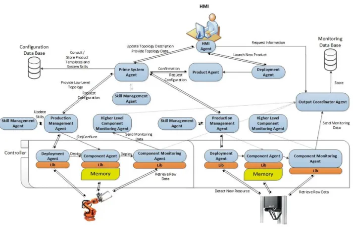
In its core PRIME is based upon a distributed, highly-scalable multiagent architecture comprised of different generic entities. Each entity plays a distinct role in order for the system to provide all the capabilities described above, such as the capacity to easily reconfigure associated components or to extract and monitor data directly from the shop-floor level.
An overview of the generic agents that support PRIME’s architecture can be seen in Figure 3.1.
Figure 3.1 - PRIME Architecture Overview
Chapter 3 Architecture
Table 3.1 - PRIME Agents and their Descriptions
Role Name Description
Suppor
t
Human Machine Interface Agent (HMIA)
The HMIA acts as the bridge between the user and the architecture by communicating directly with the Human Machine Interface (HMI). This agent allows the HMI to acquire and display relevant information, such as the production requirements for a certain product, by providing it with a variety of services that can be called to trigger the necessary behaviours in the remaining agents that will provide said information. It can also initiate the process of launching a new Product Agent, hence triggering the reconfiguration of the system for a new product variant.
Deployment Agent (DA)
The DA is responsible for launching other PRIME agents, therefore playing a vital role in both the reconfiguration and monitoring aspects of the architecture. Consequently it is mandatory that each machine intended to run PRIME agents has one DA running in it prior to their launch.
Execut ion / R econf igu rat io n
PRIME System Agent (PSA)
This agent is the highest-level entity in the system’s hierarchy. It is mainly responsible for managing the semantic model and the repository which contains information pertaining to the entire system, having therefore a large amount of information flowing through it.
Production Management Agent (PMA)
Each PMA is responsible for managing a subsystem, detaining all the information concerning its topology and skills. Its existence is one of the key factors that allows a system to be modulated as a tree of agents with different
layers of complexity, improving the system’s scalability and
modularity.
Skill Management Agent (SMA)
SMAs are the entities in control of the skill generation process which are always linked in a one-to-one relationship to a PMA. Following a pre-determined set of rules, they are capable of verifying the possibility of creating higher-level skills from the pool of already existing ones, informing their respective PMA of any new skills it may be capable of offering.
Component Agent (CA)
A CA is a low-level entity which abstracts a physical resource of the system (e.g. a gripper or a robot), encapsulating all the information related to that device. It is upon the CA that falls the responsibility of reconfiguring its associated component.
Product Agent (PA)
Architecture Chapter 3
Role Name Description
Moni
to
ri
ng
Component Monitoring Agent (CMA)
Within the monitoring module, the CMA is the entity at the lowest level of the architecture. Each CMA has an associated CA, being therefore responsible for all the monitoring
activities related to that agent’s associated component. More specifically, a CMA periodically collects raw data from a physical device and pre-processes it according to certain rules, extracting relevant information related to its performance, such as Transition Times (TRT) and Action Times (ACT), finally sending it up the monitoring tree.
Higher-Level Component Monitoring Agent (HLCMA)
Applying the concept of PMA to the monitoring architecture, the HLCMA is one of the key elements that enables the existence of the monitoring tree. As the name indicates, its
purpose is similar to the CMA’s, simply transposed to a
higher level of abstraction. Being linked to a PMA, the HLCMA can receive not only raw data related to the associated subsystem from a computational device, e.g. Programmable Logic Controllers (PLC), but also pre-processed data from other CMAs or HLCMAs monitoring cooperating entities of that subsystem.
Output Coordinator Agent (OCA)
OCAs are the highest-level entities of the monitoring architecture. Working as a cloud of agents sharing the same purpose, they act as a bridge between the monitoring environment and the other external entities, such as historical repositories and data processing networks capable of computing large amounts of data. For this reason, all the data collected and pre-processed by the CMAs and HLCMAs is sent to one of the available OCAs in the cloud in order for it to be sent to relevant external entities.
Chapter 3 Architecture
3.2.
Supporting Concepts for Reconfiguration
Despite being outside the scope of the work developed for this thesis, it is still important to
mention PRIME’s Reconfiguration environment, considering that it constitutes one of PRIME’s most defining characteristics. The multiagent-based reconfiguration environment enables PRIME to describe and reconfigure manufacturing systems without the need to physically modify already existing structures, making these systems more dynamic and robust. Some concepts supporting the reconfiguration approach are described in this section.
3.2.1.
Skill
In accordance to the definition provided in (Orio, Rocha, Ribeiro, & Barata, 2015), skill is in essence something that can be executed by a certain component or subsystem (group of components functioning as a whole), encapsulating its capabilities.
Considering the amount of different variations of skills that can exist, it is important for these skills to provide enough information in their specifications for them to be defined regardless of the entity that offers them. Considering this, a skill should have at the very least a certain amount of associated information, namely a unique ID, a name, a brief description and a list of parameters to control its execution.
Skills can be further classified as:
Simple Skills (SSK) – These are atomic capabilities provided by an entity which may or may not match a process.
Complex Skills (CSK) – At a higher level of abstraction, whenever an SSK is not enough to execute a certain process by itself, a new CSK should be created (if possible) by combining two or more available skills following a pre-determined set of rules, in order to allow the execution of said process by enabling more complex functionality (Antzoulatos et al., 2015).
3.2.2.
Configuration
Architecture Chapter 3
parameters facilitates the reconfiguration process by providing a selection criterion for the possible configurations.
3.2.3.
Semantic Model
When using a distributed approach built upon autonomous and cooperative entities, it is important to verify that the semantic content is preserved during the communication process (Borgo & Leitão, 2004). In PRIME’s specific case, as stated in (Orio et al., 2015), the semantic language developed by UNINOVA, displayed in Figure 3.2 specifies the structure for the knowledge models and system’s communication in general. It captures the main characteristics of the physical resources and their aggregations as a system, encapsulating enough information to support the extraction of knowledge required to promote self-awareness, monitoring and the capacity to adapt to changing conditions (such as those introduced by disturbances).
Figure 3.2 - Core concepts described in the PRIME semantic language - Adapted from (Orio et al., 2015)
Chapter 3 Architecture
3.3.
Supporting Concepts for Monitoring
3.3.1.
Data Extraction
Data extraction is usually viewed as a problem mainly concerning system integration, consisting on the retrieval of available data provided by a system’s data sources (e.g. PLCs and other devices that can provide and store data related to the system’s execution)(A. D. Rocha et al., 2015). This process usually leads to the acquisition of raw data which requires further processing in order for it to be useful in regards to the description of the system or its analysis. For instance, the bits
stored in a controller’s memory which describe a state indicated by sensors and actuators can be a
good example of raw data.
Data can also be divided into different types. The definitions of states and timespans are particularly useful and can be found below.
3.3.2.
State
A state indicates the condition of an entity at a certain point in time according to any given
number of variables, in this case the values given by a system’s sensors and actuators.
Associating this to the fact that most data extracted directly from a data source is usually raw, unprocessed data, it is possible to further divide states into two groups, namely Raw States (RST), which are given directly by a certain value extracted from the data source, and Computed States (CST), referring to those derived from processing a set of extracted values.
3.3.3.
Timespan
A broad definition of timespan would be the time elapsed between two relevant states. However, as mentioned in (A. D. Rocha et al., 2015), in an industrial manufacturing setting (and more specifically in the study case in question) there are two categories which are particularly important to distinguish, namely Transition Times (TRT) and Action Times (ACT).
A Transition Time is the time it takes a certain resource to physically move from one position to another, being usually associated with three different states as illustrated in Figure 3.3. In this example the transition is performed by a clamp, indicating the time needed for it to close. The initial state is related to the point right before the beginning of the transition, the intermediate state indicates the transition itself and the final state refers to the end of said transition, as indicated by a sensor that
Architecture Chapter 3
component’s condition. By computing its moving average and trend, possible increases in these values can often be interpreted as a sign that maintenance is required for the associated component.
Figure 3.3 - Transition Time
Another interesting timespan is the ACT. An ACT represents the delay verified since an input is signalled and the point in time where the corresponding action starts, being therefore directly
related to the component’s responsiveness.
An example of an ACT can be seen in Figure 3.4, which illustrates a clamp closing. The elapsed time is measured since the input is triggered until the associated component actually starts the corresponding action.
Figure 3.4 - Action Time
Chapter 3 Architecture
3.4.
PRIME Monitoring Architecture
The PRIME Monitoring Architecture presents a possible solution to enable monitoring capabilities in PRIME compliant systems. The architecture employs a generic multiagent approach in order for it to be adaptable to a varied number of manufacturing systems, providing a middleware capable of bridging the gap between the devices on the shop floor and external entities such as remote historical repositories and powerful processing networks with the capacity to support large amounts of data.
An overview of the referenced architecture, composed by three distinct types of agents and their respective interfaces, can be seen in Figure 3.5. This illustration is followed by a detailed explanation of the main procedures that constitute the monitoring process as a whole, namely agent deployment, data extraction, data pre-processing and data exportation.
Figure 3.5 - PRIME Monitoring Architecture
Architecture Chapter 3
despite having similar functionalities acts at a higher-level of abstraction, enabling the creation of a tree of monitoring entities. Finally both of these types of agents communicate with the OCA cloud with the purpose of finding an available OCA to relay their collected and pre-processed data to the appropriate external entities.
3.4.1.
Topology Acquisition and Agent Deployment
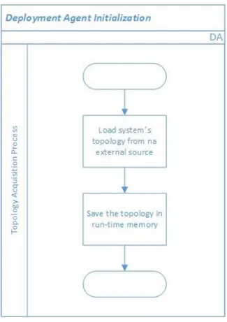
As described in Table 3.1, the DA is the agent responsible for launching new agents in the system. This operation can happen in two distinct situations, more specifically the moment the DA is initialized and when it detects that a new component has been plugged.
When the DA is initialized, before it launches any other agents on the platform it provides the ability to, if desired by the manufacturer, autonomously discover the topology that describes the system being monitored. With this purpose in mind, using a Hardware Detection Library (HDL) it can consult an external source to acquire this information. This behaviour is depicted in Figure 3.6.
Figure 3.6 - Deployment Agent Initialization
Chapter 3 Architecture
This generic behaviour makes it possible for the architecture to be applicable to a wide array of different manufacturing systems, regardless of the number or type of existing components.
DAs also play a vital role in enabling P&P characteristics for a given system by detecting changes in its topology during runtime, allowing components to be plugged or unplugged without the need to stop the entire line. This behaviour can be seen in Figure 3.7.
Figure 3.7 - P&P Component Detection
This is achieved by periodically checking the external topology source, using the HDL interface, to see if anything has changed when compared to its latest recorded information. As shown in Figure 3.7, in case a modification is detected, the DA acts accordingly either by launching a new CA (in case a new device is plugged) or by initiating the process to remove agents associated with an unplugged device from the platform.
Architecture Chapter 3
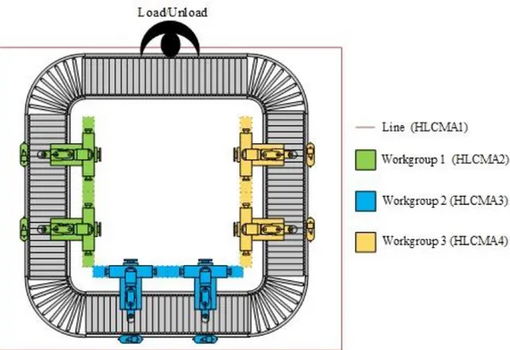
Figure 3.8 - Example Line for the Topology Acquisition
The highest level entity is the line itself, which would be abstracted by a PMA and an associated HLCMA. This subsystem comprises three other subsystems, namely Workgroups 1, 2 and 3. Each workgroup (WG) is in turn composed by two robots and two part detectors (PD), each abstracted by a CA and an associated CMA, resulting in the monitoring tree seen in Figure 3.9.
Figure 3.9 - Example of a Monitoring Tree
Chapter 3 Architecture
3.4.2.
Data Extraction Procedure (DEP)
In order for data to be pre-processed it is first and foremost necessary to extract it from its sources, making the DEP the first stage of the actual monitoring process itself.
They key players in this procedure are the CMAs and HLCMAs. As it can be verified in Figure 3.5, both types of agents possess two different communication interfaces to external entities, more precisely the Event Description Library (EDL) and the Data Acquisition Library (DAL).
In order for the agents to recognize all the possible events and values related to their abstracted component or subsystem, each agent possesses its own Knowledge Base (KB) capable of storing the rules and descriptions that define their associated monitoring data. For this purpose, the EDL should contain methods to allow the CMAs and HLCMAs to access an external data source (e.g. a DB or an XML file) in order for them to learn information regarding the data they will be monitoring, more specifically which values they should extract, how often they should be extracted (polling rate) and all the rules concerning the conditions that define possible events that need to be computed by the agents themselves (pre-processing).
This learning process takes place during the agent’s initialization and can be seen in Figure 3.10. Upon waking up the agents load the monitored data description related to their associated component using the EDL, storing it in their KB to enable the data extraction process.
Architecture Chapter 3
After acquiring the necessary information in the previous step, the CMAs and HLCMAs can begin extracting data from their associated components and subsystems respectively. This extraction
can happen in two different ways, depending on the DAL’s implementation. Both methods can be seen in Figure 3.11.
Figure 3.11 - Data Extraction Process
As observed in Figure 3.11, data can either be extracted periodically according to a certain polling rate, usually specified in the monitored data description, using methods provided by the DAL, or it can be acquired via events fired by the DAL itself, for instance when the underlying technology
fires a “value-changed” event upon detecting that a certain monitored value has changed since its last extraction.
Chapter 3 Architecture
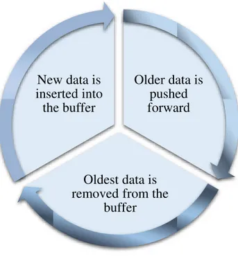
Figure 3.12 - Circular Buffer's Functionality
As seen above, as fresh data is inserted into the agent’s buffer, all previously stored
information is pushed forward, forcing the oldest, outdated data out. This functionality allows the agent to only keep relevant data in its memory, whilst flushing out obsolete information.
All collected data is also sent upwards to an available OCA in order for it to be exported. This behaviour will be approached in further detail in section 3.4.5.
3.4.3.
Higher-Level Data Propagation
The main difference between the CMA and HLCMA resides in their different levels of abstraction. While the CMA acts at the component level, the HLCMA stands at a higher point in the monitoring tree, being responsible for abstracting groups of components cooperating amongst themselves, which are in essence subsystems.
As such, taking into account that these agents operate at a higher-level of abstraction, it can be useful for them to not only collect data, when possible, directly from the subsystems themselves but also to receive the data acquired and pre-processed by their associated lower-level agents. This process is illustrated in Figure 3.13.
Older data is
pushed
forward
Oldest data is
removed from the
Architecture Chapter 3
Figure 3.13 - Higher-Level Data Reception
Chapter 3 Architecture
This is achieved by having every monitoring agent initiate a data propagation process upon either collecting or processing new data. A communication is initiated with its parent HLCMA (if it exists) in order for said data to be transmitted, which in turn replies with the transmission’s status. Afterwards the HLCMA stores the new data, propagates it in similar fashion and initiates the processing behaviour, as shown in Figure 3.13 .
3.4.4.
Data Processing Algorithm (DPA)
The DPA is one of the key points of the monitoring structure, being used by the CMAs and HLCMAs to infer more complex knowledge from the raw data collected through the regular monitoring process.
Based on the raw data extracted from the physical devices, the DPA allows the CMAs/HLCMAs to acquire higher-level data, such as states and timespans, that wouldn’t normally be available to be extracted directly from the devices themselves. This process is the cornerstone that enables the proposed architecture to provide more useful data to the external processing entities, permitting them to perform the analysis of relevant trends and tendencies in the extracted data’s values.
The inference process consists initially in computing the raw data values according to a certain rule set stored in each agent’s respective KB, as seen in Figure 3.14.
Figure 3.14 - Knowledge Inference Example - Clamp's Current State
However, as more complex states are inferred they can also be used to compute new data
Architecture Chapter 3
Chapter 3 Architecture
As already stated in 3.4.2, during the CMA’s and HLCMA’s initialization process all the information regarding what kind of events can be computed and the rules that define them is loaded
onto each agent’s KB. The agent then waits until new monitored data is received, regardless of it coming from the agent’s own DEP or its children’s, starting the main processing cycle upon its
arrival.
The processing cycle consists in a series of procedures that for each possible value to be computed, allow the CMA/HLCMA to decide whether the collected data present in its circular buffer in that given moment is enough to compute said value, according to the conditions defined in the monitored data description contained in its KB.
While the processing of some data types, for instance states, is done in a fairly straightforward manner by simply checking if all conditions that define the referenced data type are met, the same does not apply to timespans.
In the former’s case, only a single set of conditions must be met in order for a given state to
be computed. Therefore all that is required is for the agent to iterate over the entire set of conditions, checking if for each and every one of them there is a value stored in the circular buffer that satisfies it. If all conditions are met, the new inferred state itself is then stored in the circular buffer and propagated to the upper layers of the monitoring tree.
However, in the latter’s case, two different sets of conditions must be met in order for a timespan to be calculated, namely those that define the beginning and the end of the relevant period of time. For this reason, the agent starts by checking if all the ending conditions are met, similarly to how a new state is processed. If they are, it stores the latest timestamp among the values that verify that set of conditions, moving on to repeat the process for the starting conditions. However, if at either stage the conditions are not verified the computed value is discarded and the agent starts the cycle anew for the next possible computed value.
If all the conditions are satisfied then the CMA/HLCMA computes the timespan by calculating the difference between the timestamps associated with the starting and ending conditions sets, storing it in its circular buffer and sending it up the monitoring tree.
3.4.5.
Data Exportation
Architecture Chapter 3
is selected based upon a negotiation process following a specific metric (e.g. response time), which can be seen in Figure 3.16.
Figure 3.16 - OCA Negotiation
4
Chapter 4.
Implementation
This chapter describes the implementation of the monitoring architecture detailed in Section 3.4, developed using Java alongside the Java Agent Development Framework (JADE).
JADE facilitates the implementation of agent-oriented approaches, serving as a MAS-oriented distributed middleware that provides a flexible domain-independent infrastructure. This infrastructure facilitates the development of complete agent-based applications by providing a run-time environment implementing the required basic features required by agents, their core logic and various auxiliary graphical tools (Bellifemine, Caire, & Greenwood, 2007).
The Java programming language was chosen not only for integration purposes (since the project in which the proposed architecture was integrated for the validation process had been developed in Java) but also due to the fact that JADE is written completely in Java, benefitting from the varied array of language features and third-party libraries widely available.
The present chapter is structured as follows: Section 4.1 starts off by providing a brief explanation of the communication protocols adopted for the agent communication, namely FIPA Request and FIPA Contract Net. Afterwards Sections 4.2, 4.3, 4.4 and 4.5 present a detailed
description of each agent’s implementation, including its associated data model and respective
Implementation Chapter 4
4.1.
Agent Communication
Since all JADE agents are FIPA compliant (Bellifemine, Poggi, & Rimassa, 1999), the communications established between were implemented according to the specifications of two different FIPA protocols, FIPA Request and FIPA Contract Net. Both protocols are analysed in the sub-sections ahead.
4.1.1.
FIPA Request Protocol
The FIPA Request Protocol (FIPA, 2002) allows agents to perform point-to-point communications, being therefore able to request another agent to perform a certain action. As illustrated in Figure 4.1, this protocol specifies that the communication starts when the Initiator agent sends a request to the Participant agent.
Figure 4.1 - FIPA Request Protocol