Nonlinear analysis of the progressive collapse of
reinforced concrete plane frames using a multilayered
beam formulation
Análise não linear do colapso progressivo de pórticos
planos de concreto armado utilizando elemento de viga
com seção transversal discretizada em camadas
a Department of Civil Engineering, Federal University of Ouro Preto, Ouro Preto, MG, Brazil;
b Building, Architecture, and Town Planning Department, Université Libre de Bruxelles, Brussels, Belgium.
Received: 15 Feb 2014 • Accepted: 19 Aug 2014 • Available Online: 02 Oct 2014
Abstract
Resumo
This work investigates the response of two reinforced concrete (RC) plane frames after the loss of a column and their potential resistance for progressive collapse. Nonlinear dynamic analysis is performed using a multilayered Euler/Bernoulli beam element, including elasto-viscoplastic effects. The material nonlinearity is represented using one-dimensional constitutive laws in the material layers, while geometrical nonlinearities are incorporated within a corotational beam formulation. The frames were designed in accordance with the minimum requirements proposed by the reinforced concrete design/building codes of Europe (ib [1-2], Eurocode 2 [3]) and Brazil (NBR 6118 [4]). The load combinations considered for PC analysis follow the prescriptions of DoD [5]. The work veriies if the minimum requirements of the considered codes are suficient for en -forcing structural safety and robustness, and also points out the major differences in terms of progressive collapse potential of the corresponding designed structures.
Keywords: progressive collapse, reinforced concrete, nonlinear analysis, corotational formulation, layer discretization.
Este trabalho investiga a resposta de dois pórticos planos de concreto armado à perda de uma coluna e sua capacidade de resistir ao colapso progressivo. A análise não linear dinâmica é realizada utilizando um elemento de viga baseado na teoria de Euler/Bernoulli com seção transversal discretizada em camadas. A não linearidade física é representada através de relações constitutivas unidimensionais, incluindo efeitos viscoplás -ticos. A não linearidade geométrica é incorporada através de uma formulação corrotacional. Os pórticos foram projetados de acordo com os requisitos mínimos das normas de projeto/construção de estruturas de concreto armado Europeias (ib [1-2], Eurocode 2 [3]) e Brasileiras (NBR 6118 [4]). As combinações de carregamento consideradas na análise de colapso progressivo estão de acordo com DoD [5]. O trabalho veriica se os requisitos mínimos das normas consideradas são suicientes para garantir a robustez e a segurança estrutural e aponta também as diferenças mais relevantes em termos da suscetibilidade dos pórticos ao colapso progressivo.
Palavras-chave: colapso progressivo, concreto armado, análise não linear, formulação corrotacional, discretização em camadas.
C. E. M. OlivEiRA a,b [email protected]
E. A. P. BAtElO a [email protected]
P. Z. BERkE b [email protected]
R. A. M. SilvEiRA a [email protected]
1. introduction
Progressive collapse corresponds to a structural failure mechanism triggered by the irreversible damage of one or more key structural el-ements which forces a redistribution of the loads and internal forces in the structure (Li et al. [6]), resulting in changes in the loading of the
transversal sections of the beams and columns. This may, in turn, initiate further propagation of structural damage by the progressive failure of the overstressed remaining structural elements.
Progressive collapse (PC) is usually described as a catastrophic dynamic behavior of civil engineering structures (Kim et al. [7])
that is inluenced by both material (Tsai and Lin [8]; Kwasniewski [9]) and geometrical nonlinearities (Tan and Pham [10]). It leads to inancial and, sometimes, human losses (Marjanishvili [11]). Many authors have investigated how to prevent progressive col -lapse by (1) identifying key elements of which failure may initiate PC, and (2) enhancing the overall structural robustness in order to enforce proper and adequate load redistribution to guarantee the stability of the remaining structure (Izzuddin [12]; Khandelwal and El-Tawil [13]).
Section ‘10.3 Estados limites últimos (ELU)’ on NBR 6118 [4] spe -ciically establishes that the safety of reinforced concrete struc -tures must always be veriied against: the limit states related to the depletion of the resistant capacity in the complete structure (and in its individual structural elements) considering, among others, the geometrically nonlinear effects; the limit states caused by dynamic solicitations and; the progressive collapse limit state.
NBR 6118 [4] also deines the appropriate lexural reinforcement for guarantying local structural ductility against progressive collapse. However, this deinition is made only for lexural reinforcement of RC slabs, not beams or columns. Since no speciic guidelines are given on how the veriication against progressive collapse should be performed, our contribution consists in developing and apply-ing a dedicated computational tool for the study of the structural response to extreme loading with a relatively low number of model -ing assumptions. Our approach includes a dynamic description of the problem with a physically-based sectional degradation of the composite cross sections (i.e., the reinforcement ratio and scheme
are explicitly represented), rate-dependent material behavior of the constituents and catenary effects due to the developed geometri-cally nonlinear framework. Section 2 describes our contributions to the computational modeling of progressive collapse and to the numerical analysis of reinforced concrete structures.
In this work, the progressive collapse phenomenon is investigated by analyzing the structural response of two plane frames that rep -resent a ive story reinforced concrete (RC) building, designed in accordance with the European (Eurocode 2 [3]) and the Brazilian building codes (NBR 6118 [4]). Even though sharing the same ar -chitectural geometry, the obtained frames are different in terms of loads, element cross sections, reinforcement scheme, reinforce-ment ratio, and consequently, structural robustness, since these codes prescribe different requirements. The Eurocode-based design was carried out using the commercial software Diamonds (Buildsoft [14]) while the Brazilian design was performed on Cype -cad (Cype [15]). More detailed information on these frames and their design process can be found in Section 3.
Section 4 presents the numerical tool and provides information on the multiscale approach (Iribarren et al. [16]) used to investigate the
PC structural behavior in this work, the description of the corotational
beam formulation (Crisield [17]; Battini [18]) and the material constitu -tive models. Section 5 is aimed at the presentation and the discussion of the results obtained in nonlinear dynamic analysis. Finally, conclu-sions and perspectives of this work are presented in Section 6.
2. Main contributions
The prime numerical novelty of our approach is the introduction of catenary effects in a layered beam formulation for compos-ite cross-sections using a corotational framework, which was not included in earlier modeling attempts (Iribarren et al. [16]). The
extension of the numerical approach with additional complexity allows a better approximation of the physical phenomenon, since it reduces the number of modeling assumptions. This approach leads to a more realistic analysis due to the coupling of many dif-ferent aspects of the structural behavior, from material properties to the interaction between the deformed geometry and the loads. The majority of works concerning the veriication of progressive collapse usually considers structural designs based on European, North-American or Asian building codes. To the best knowledge of the authors, the type of progressive collapse veriication per -formed here was not attempted before for a NBR-based building. The application of the resulting computational tool to the compari-son between two structures designed following different building codes, European and Brazilian, but having identical architectural geometry is a second originality of the presented work.
3. Structural design
The plane frames consist of an 18 m high ofice building with ive levels. The ground loor height is 6 m and the height of the other loors is 3 m each. The frame is 48 m long, equally divided in 6 m bays as shown in Figure 1. Since the presented work aims at investigating the inluence of catenary effects, due to the large changes in the geometry, the removal of an interior column was considered. A similar procedure was adopted by Lew et al. [19], Yi et al., [20].
The Eurocode-based design was carried out using the commercial software Diamonds (Buildsoft [14]) and presented in Iribarren et al.
[16], from where the parameters used in this work were directly taken. The material parameters and geometry of the structural elements
therefore assume European practical values. On the other hand, the Brazilian design was speciically performed for this work on Cypecad (Cype [15]), assuming the minimum speciications of NBR 6118 [4]. Thirty centimeters thick concrete slabs were used for the Eurocode-based frame, including a concrete cover layer of 10 cm. As dis -cussed by Lee and Scalon [21], Eurocode 2 [3] does not deine mini -mum thickness for concrete slabs. Instead, the thickness is obtained as a function of the inal reinforcement ratio. The European design assumes minimum reinforcement ratio (Iribarren et al. [16]), therefore
it is correct to assume that the thickness of 20 cm used in that work is also minimum. Slabs of 13 cm are used for the Brazilian design (without any cover layer). The lack of a cover layer in the Brazilian building is justiied by the herein assumed methodology of obtaining a design based on minimum requirements. These slabs do not pro-vide any resistance; however, they were adequately dimensioned and veriied against maximum allowable displacements.
Live and dead loads are summarized in Table 1. The total load, shown in the same table, combines the total dead load value with 50% of the live loads, as recommended by DOD [5]. The self-weight load is translated into loads per unit length through the multiplication of the reinforced concrete weight density (24 kN/m3) by the volume
of the structural element and subsequent division by its length. For self-weight of the slabs, the length is taken as the beam length:
n for the Eurocode-based frame:
(0.30m X 6m X 6m X 24kN/m3) /6m = 43.2kN/m
n for the NBR-based frame:
(0.13m X 6m X 6m X 24kN/m3) /6m = 18.7kN/m
The following assumptions were made during the design process:
n all loor beams are the same, since the same loads were con
-sidered at all loors;
n all columns are considered the same, i.e. although upper loor
columns bear smaller loads, they have the same section and reinforcement scheme as ground columns;
n the height and the width of a structural element are constant along the length;
n assuming Aggressiveness Class II, the NBR-based design has
a concrete rebar cover of 2.5 cm; a 5 cm concrete rebar cover is taken for the European design, as in Iribarren et al. [16];
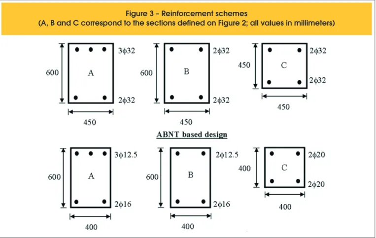
n the bottom reinforcement is assumed continuous in both designs; n the continuity of 2/3 of the top beam reinforcement (Figs. 2 and
3) is considered in both designs;
Figure 2 – Reinforcement continuity
Figure 3 – Reinforcement schemes
n Bond and anchorage were considered during the design pro -cess but are not included in the progressive collapse analysis;
n Perfect bonding between concrete and steel is assumed; n stirrups are considered during design, but not represented in the
PC analysis, i.e. the increase in the concrete strength and ultimate
strain resulting from the coninement are not taken into account. Although the design of the Eurocode-based building is the same as the one presented by Iribarren et al. [16], the present analysis
applies a further developed numerical formulation that includes nonlinear geometrical effects (catenary effects). Another difference resides in the fact that concrete strength under tension is not taken into account here, based on usual reinforced concrete practice. Besides, the inluence of strain rate effects was not taken into ac -count in Iribarren et al. [16] for the case middle column removal.
These different features are described in the next section.
4. Geometrically nonlinear formulation
with a multilayered beam approach
The main contribution of this work from a computational point of view is the incorporation of the multiscale computation of sectional stress-es (Iribarren et al. [16]) into the geometrically nonlinear kinematics
described by a corotational Bernoulli beam formulation. This sec -tion summarizes the main ingredients of the computa-tional model -ing tool. It presents the main aspects of the corotational formulation used for introducing geometrically nonlinear effects in the multiscale numerical formulation, as well as the adopted constitutive laws for the materials and the governing equations in structural dynamics.
4.1 Corotational beam kinematics
Geometrically nonlinear effects, such as catenary actions, are
effects that take place when changes in geometry have signiicant inluence on the structural behavior (Bonet and Wood [22]). In the works by researchers as Battini et al. [23], Souza et al. [24], Lew et al. [19] and Yi et al. [20] the importance of considering these effects
when analyzing steel/reinforced concrete/composite structures was clearly demonstrated. Tan and Pham [10] have also shown that catenary effects may play an important role on mitigating PC. In this work, the applied geometrically nonlinear beam kinematics represented by a corotational formulation allows for an investiga-tion of possible catenary effects.
The corotational formulation, as presented in Crisield [17] and Battini [18], is a reinterpretation of the deformation of a beam el -ement or, in the most general case, a tridimensional body. This reinterpretation consists in using a local reference system attached to the beam element, different from the global, structural reference system (Fig. 4).
In this corotational approach, strains and stresses in a given el -ement are computed in the (individual) local reference system attached to this structural element, which allows decoupling the rigid body rotation from the actual deformation. The relation be-tween the displacements in the global structural reference system, {qe}T = {u
1 w1 θ1 u2 w2 θ2}, and the ones in the local system of a
structural element, {qe}T = {u θ
1 θ2}, is given by:
(1)
{
–
u–
–
θ
1θ
2}
T=
[
θ
l
f1-l
-α
iθ
2-α
]
=
[
θ
1-(β-β
l
f-l
i 0)
θ
2-(β-β
0)
]
where lf, li and α denote the deformed length, the undeformed length and the rigid body rotation of the element, respectively, β represents the current angle between the element and the global reference system, and β0 represents the original value of this angle
in the undeformed coniguration.
In this work, a linear shape function is used for interpolating the axial displacements in the local frame of the beam element, while a cubic interpolation is used for the transverse displacements:
(2)
where u, θ1 and θ2 are the axial elongation and the nodal rotations
in the local corotational frame.
The average axial strain and beam curvature computed at an integration point of the beam inite element are therefore given by:
(3)
ε_
_
=
∂
∂x =
u
u
l
iχ
=
∂
∂x
2w
2=
(
-
4
l
(
i
+
6
l
i2x
)
θ
)
_
_
1
+ -
2
l
i+
6
l
i2x
θ
2Figure 4 – Corotational reference system
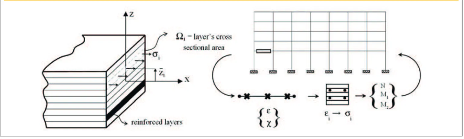
4.2 Multilayer discretization of
an Euler-Bernoulli beam
The formulation uses a layer discretization of the transversal sec -tion for determining stresses in the sec-tion of an Euler-Bernoulli beam inite element. Internal forces are obtained from the integra -tion of sec-tional stresses over three Gauss points along the length of the element.
The discretization of the transversal sections, deined at the Gauss points along the length of the beam, consists of the portioning of the reinforced concrete (composite) section into longitudinal layers (Fig. 5). Note that, this produces a multilevel description that links the dynamic equilibrium on the structural level to the equilibrium of the generalized forces applied at the transversal sections. The average axial strain and beam curvature computed at an in -tegration point (Eq. 3) are used to obtain the total (axial) strain in each layer:
(4)
ε
i
=
ε
_ _
-z
i
χ
where ε is the beam axial strain and, for each layer i, ziis the
posi-tion of layer center of mass with respect to the neutral axis of the section, χ is the beam curvature and εi is the total axial strain in
a given layer. Note that Eq. (4) implies the assumption of perfect strain compatibility between the layers. This – among others – pre-cludes the modeling of delamination between concrete and steel. Using (nonlinear) constitutive relationships for concrete and steel, it is therefore possible to determine the one-dimensional axial stresses acting in each layer, σi,conc. and σi,steel. A mixture rule is then
used for obtaining the total axial stress, as shown below:
(5)
σi=
Ωi-Ωi,steel
Ω
i
σi,conc.+
Ωi,steel
Ω
iσi,steel
where σi is the one-dimensional total stress on layer i, Ωi is the
layer total cross-sectional area and Ωi,steel is the fraction of the layer
cross-sectional area occupied by steel. Equation 5 is based on a perfect bonding assumption between concrete and steel within a given layer.
At each integration point (represented on Figure 5 by cross marks along the element), the section generalized stresses are obtained using:
(6)
Σ
gen=
[
N
M
]
=
[
-Σσ
Σσ
iiy
_
Ω
iΩ
i i]
These generalized stresses are used to obtain an internal force vector, {flocal}T={N M
1 M2} , which is conjugated to the displacement
vector in the local frame given in Eq. (1). The global (structural) internal force vector {fglobal}T={fn
1 f t
1 c 1 f n
2 f t
2 c2 } can then be
de-duced from {flocal}T as shown in Crisield [17] and Battini [18]. De
-tailed technical information on the derivation of these quantities and the stiffness matrix of the inite element can also be found in the latter works.
The main advantage of this approach is that it makes possible the physical representation of the reinforcement within the cross sec-tion and of a gradual secsec-tional degradasec-tion effect, consequence of progressive layer failure.
4.3 Constitutive models for concrete and steel
The multilayered beam formulation presented uses one-dimen-sional constitutive laws for concrete and steel to determine the stresses in each material and, afterwards, in each layer . Accord -ing to Eurocode 2 [3], class C30 concrete and S500 steel were used for the European structural design. As mentioned before, the design process of the Brazilian structure was aimed at producing a frame based on the minimum parameters of NBR 6118 [4], includ -ing the material properties as concrete strength and steel strength. C20 concrete is the lowest concrete class allowed by NBR 6118 [4] (except for reinforced concrete foundations, for which it is ac -ceptable to use C15 concrete). For that reason concrete C20 was adopted for the Brazilian structure in association with CA50 steel bars. The constitutive model for these materials is described through a bilinear approximation of the stress-strain behavior, as presented in the following.
Figure 5 – Multilayer discretization of a beam section and scheme of the multiscale framework
int
The model for the behavior of concrete was based on recommenda-tions established by Eurocode 2 [3] and ib [1-2], as shown on Figure 6. The following assumptions are used to deine this simpliied model:
n although in some scenarios tensile stresses may play a non-negligible role in structural strength, any structural strength associated with tensile loading is not taken into account, i.e. concrete under tension is considered to be fully cracked and the corresponding tensile stresses are neglected;
n strains and stresses are linearly proportional on the ascending part of the curve, as recommended by Eurocode 2 [3], instead of the nonlinear curve proposed by ib [1-2]. Young’s moduli were set as 32 GPa for C30 and 25 GPa for C20 concrete, respectively;
n for quasi-static loading conditions, the plastic regime is repre-sented by a plateau at a stress of 37.9 MPa for C30 concrete and 20 MPa for C20 concrete;
n the ultimate strain under compression in both types of con-crete is deined as 0.35%, after which any increase in the strain level will immediately decrease the stress to zero and keeps it at this level in the subsequent loading steps. In this work, this assumption associated with the multilayer discretization allows the investigation of material degradation due to compressive concrete failure (crushing).
According to Eurocode 2 [3] and NBR 6118 [4], the bilinear curve on Figure 7 represents the relationship between stress and strain for steel under quasi-static loading conditions. The following ad-ditional information can also be related to the constitutive behavior of S500 steel and CA50 steel:
n the steel behavior in tension is similar in both compression and tension;
n buckling of compressed steel bars is not considered;
n the elastic modulus, yield stress and ultimate strain are equal to 200 GPa, 500 MPa and 4%, respectively;
n just as it was assumed for concrete, stresses in the layers van-ish as the strain reaches values larger than 4%, representing steel fracture;
n the ratio between ultimate stress and yield stress is equal to 1.06 (Iribarren et al. [16]).
In order to account for the strength enhancement provided by the strain rate dependence of both steel and concrete material be-havior (Bischoff and Perry [25]; Malvar and Crawford [26]), the constitutive models deined above are extended by a strain rate dependent material behavior. The elastic modulus of concrete is therefore made dependent on the strain rate, see Iribarren et al.
[16]) for more details. Moreover, to include the strain rate effects in the irreversible behavior of concrete and steel, a Perzyna type viscoplastic model is used (Heeres et al. [27]), introducing viscous
terms in the constitutive laws. The viscoplastic strain rate, as used in Iribarren et al. [16]), is a function of the overstress value fand is
given as follows:
(7)
ε
vp=
1
η
f
σ
_
0 Ndf
d
σ
v
v
where 〈 〉 are called MacAulay brackets, εvpis the viscoplastic strain
rate, ηis the initial yield stress; η and N are viscosity parameters. The parameter σ
0 depends on the strain rate and= 1, as assumed
by Iribarren et al. [16] in order to obtain a good agreement with the
experimental results of Malvar and Crawford [26]. The overstress function (f) is given by (σ–σ), where σ is the one-dimensional stress and σ is the current yield stress.
4.4 Governing equations in dynamics
Since progressive collapse is a dynamic phenomenon, the struc -tural equilibrium is described in a dynamic framework in the nu-merical model. Equilibrium in dynamics is represented by the fol-lowing equation:
(8)
{f
int
({q},{ }
q )}+[M]{q}={f
ext
}
Figure 6 – Constitutive model – concrete
in compression for quasi-static loading
Figure 7 – Constitutive model – steel
for quasi-static loading
.
on which an implicit Newmark integration scheme is applied and where
{f
int}
represents the internal force vector, dependent on the displacements {q} and the displacements rates {q} . The mass ma-trix is represented by[M]
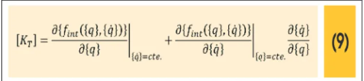
, {q}is the vector of nodal accelerations and {fext}, the external force vector. Note that no numerical/artiicial damping is introduced in the system of equations.Since the internal forces are strain rate dependent, their variation with respect to the displacements, i.e. the structural tangent
opera-tor, is also dependent on those rates and therefore introduces a
viscous damping term:
(9)
In the previous equation, the second term on the right side introduc -es damping at the structural level due to the strain rate dependent
Figure 8 – Deformed configuration
(displacements multiplied by 10, dashed lines relate to Figure 10)
EUCO
BRCO
A
(viscoplastic) stress-strain relationships assumed for the materials. It should be noted that the mass matrix of the beam elements was here calculated considering the undeformed shape of the structure and kept constant along the entire analysis in this work. Updating the mass matrix as a function of the displacements of the structure is part of future work and can be based on Le et al. [28]).
The computational formulation presented in this section was care-fully validated using results from the literature for steel beams and frames (Crisield [17], Battini [18]) and also for reinforced concrete frames (Lew et al. [19]; Yi et al. [20]), which consisted on a correlation
to experimental results.
5. Nonlinear dynamics simulation results
Each plane frame has the same 2D discretization, constituted from approximately 900 beam elements. Forty layers are used for the discretization of the columns cross sections and sixty layers for the
beams. The structure self-weight and service loads are applied in a large period of time, deined as 1000 s, in order to prevent the inlu -ence of dynamic effects in the initial loading phase, which is ideally quasi-static. The column removal is modeled as the decrease of the reaction forces applied at point E, equivalent to the presence of the 5th ground column (Fig. 8). This is done in a short period of time (0.01 s), subsequently to the initial loading process. The response of the structure is analyzed for a period of two seconds after column removal, as in Iribarren et al. [16]. The removal time corresponds to 0.5% of the response time, which classiies the loading as impulsive (Smith and Hetherington [29]).
The removal of a column results in the inversion of the bending moments applied on the beams which must resist these changes. Results show that the reinforcements did not fail. Consequently the structures did not collapse with the middle column removal, i.e. both structures were able to overcome the loss of the column and did not initiate the progressive collapse mechanism, accord-ing to the simulation. The deformed coniguration of the EUCO (Eurocode-based frame) and BRCO (NBR-based frame) is shown in Figure 8. It is clearly noticeable that the displacements in BRCO are larger (Figs. 8 and 9). In fact, BRCO’s vertical displacements on the reference points A-E are approximately 2 times larger than the ones of EUCO (Tab. 2). The displacement values shown on Table 2 also imply that the columns located between points A and E (Fig. 8) undergo rigid body motion.
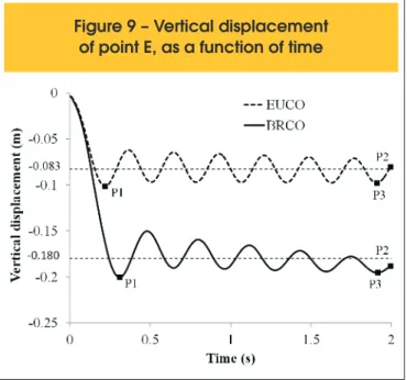
Within the time interval deined by points P1 and P2 in Figure 9, the mean value of the displacement of point E (Fig. 8) is of approxi -mately 8 cm and 18 cm for EUCO and BRCO analysis, respec -tively. Table 2 displays the vertical displacements of the reference point E for both structures. As the structures have different fre -quency of the displacement oscillation, the values shown on Table 2 were taken as the largest immediate displacements before the analysis completion, identiied on Figure 9 by point P3.
The frequency of the displacement oscillation is slightly higher for EUCO frame. There are two explanations for the larger displacements of the Brazilian frame: 1) BRCO’s structural elements have smaller sections and less reinforcement and 2) the material behavior adopted for concrete in the two simulations is different as well (Fig. 6). The state of individual structural members at any time is available from the numerical computing. In Figure 10, the symbol (∎) was used to represent sections in which steel has reached yielding and (∇) represents those in which concrete was crushed in less than 30% of the layers. It can be seen that, for both frames, the effects
Figure 9 – Vertical displacement
of point E, as a function of time
Table 1 – Recommended beam loads
EUROCODE – based design
NBR – based design Loads (kN/m) Loads (kN/m) Dead Dead Live Live Total Total Floor beams Roof beams Floor beams Roof beams 43.2 43.2 18.7 18.7 18.0 6.0 12.0 6.0 52.2 46.2 24.7 21.7
Table 2 – Vertical displacements (cm)
at reference points, at times denoted
by point P3 on Figure 9
Reference
of the middle column removal can barely be identiied on other beams and columns than the ones above the point E. However, BRCO presents a larger number of plastiied sections (158 sec -tions from BRCO against 94 sec-tions from EUCO, Fig. 10). Differ -ently from EUCO, BRCO also displays sections on which concrete was crushed.
According to the Allowable Collapse Region criterion (DoD [5]), only the bays immediately adjacent to the removed element must be af-fected. This indicates that only bays 4 and 5 could be affected in terms of collapse. Figure 10 shows that there was no collapse and that plastiication of the steel rebars only occurs in bays 4 and 5. Therefore, the Allowable Collapse Region criterion was fulilled.
6. Discussion
Both frames were designed in accordance to current building codes and consider the presence of stirrups. In this work however, stirrups are not incorporated during the PC analyses which means that their positive inluence in preventing concrete cracking, if any, is neglected. The presence of stirrups could be included in the nu-merical model by changing the constitutive behavior of concrete,
i.e. modifying the maximum compressive stress and the ultimate
strain in order to account for the coninement of the material. Designing the frames in accordance with two different codes, Eu -rocode 2 [3] and NBR 6118 [4], also resulted in using different con -stitutive behaviors for concrete. As seen in Figure 7, BRCO consid -ers lower compressive strength of concrete. Using concrete with higher compressive strength for the BRCO frame may however not systematically lead to an increase in the overall robustness of the structure. This would also result in different cross sections for the
structural elements and different reinforcement schemes during the structural design step. Therefore a new set of PC simulations should be conducted to assess the inluence of such a variation. Given the multiscale approach of the PC problem discussed here, it was necessary to deine an optimum number of layers for dis -cretizing the members cross sections, i.e. not too many layers that
would make the analysis unaffordable in terms of computational time or too few that would introduce signiicant errors in the results obtained. A preliminary step to establish the minimum number of layers to be used for the element cross sections is suggested for every new design.
The oscillation of the point above the removed column is of high importance, since it implies repeated cyclic variations of the struc-tural stress level. This scenario may accelerate the process of con-crete crushing and introduce material damage.
Both designs were able to resist PC, and the plastic strain distribu -tion was localized in the two bays above the removed column. This type of localized damage is of restricted extent which may decrease the number of losses and result in easier repair of the remaining structure. Nevertheless, it is important to stress that the plasticity distribution and structural damage may be strongly dependable on the position of the removed column (Iribarren et al. [16]), and a more
wide-spread damage may be expected in other scenarios.
Additional analyses using a geometrically linear formulation showed a response similar to the one described earlier. This im-plies that the positive inluence of (geometrically nonlinear) cat -enary effects in mitigating PC could not be triggered in the con -sidered simulations due to the relatively small displacements in the structure. However, this point should be further investigated in future works in 3D simulations and also in the analyses of different
Figure 10 – Plasticity distribution on the undeformed configuration, at the end of the analysis
(2s after middle column removal; for the sake of good visibility, only the affected areas were represented)
EUCO
RC frames.
As buildings are spatial structures, analyzing PC via a bidimen -sional formulation inevitably carries limitations. At a higher compu -tational cost, a tridimensional approach would allow the inclusion of shear and torsional effects and would also permit the modeling of failure along the three axes, allowing a more complete under -standing of the phenomenon.
For this work, the complete multiscale PC analysis of one structure took approximately 8 hours on an Intel i5 3.0 GHz personal com -puter, using a single CPU core for the computation. The computa -tional performance could be signiicantly enhanced using a parallel computation scheme, which is part of future work.
Energy conservation problems associated to the use of the coro-tational formulation in the solution of nonlinear dynamic problems were reported by Crisield and Shi [30] and Salomom et al. [31].
This inconvenience is shown to be related to the adopted time step and tends to be more severe the latter gets larger. In this work, however, time steps were in the order of 0.01s and the occurrence of such problems was not veriied.
7. Concluding remarks
This work presented the computational analysis of two reinforced concrete plane frames designed in accordance with the minimum requirements of two different building codes, from Europe and from Brazil. The problem is approached taking into account dy -namic effects, as well as material and geometrical nonlinearities. A multilayered Bernoulli beam element using corotational kine -matics was developed for this purpose. The details and assump-tions made during the design process were provided, as well as a summary of the applied numerical formulation and the material constitutive behavior.
None of the structures triggered the progressive collapse mecha-nism after the removal of a middle column, which implies that the minimum requirements of both codes are successful in providing structural robustness for the particular scenarios studied here. Larger displacements were observed for the Brazilian frame as a result of weaker design constraints. For both frames, the structural damage happened to be localized only on the loors immediately above the removed middle column.
Future research includes the updating of the structure mass matrix as a function of structural deformation, the association of plasticity and damage (elastic stiffness degradation) in the representation of the constitutive material behavior, and the use of a formulation including shear effects. The ultimate goal is the extension of the formulation to three dimensional structures which will require a par-allel implementation of the code and would allow for the inclusion of the resistance introduced by the concrete slabs and also by the out-of-plane beams.
8. Acknowledgments
The authors would like to thank CAPES, CNPq, FAPEMIG, Funda -ção Gorceix and PROPEC for the inancial support. The third au -thor was sponsored by the Fonds de la Recherche Scientiique F.R.S. - FNRS of Belgium (post-doctoral research grant ‘Chargé de Recherches’ No. 1.2.093.10.F). The authors also acknowledge the
support of F.R.S. - FNRS Belgium (grant No. 1.5.032.09.F) for the
intensive computational facilities used for this work.
9. References
[01] INTERNATIONAL FEDERATION FOR STRUCTURAL CON -CRETE (ib), Constitutive modelling of high strength/high per -formance concrete, State-of-art report, ib Bulletin 42, 2008a. [02] INTERNATIONAL FEDERATION FOR STRUCTURAL CON
-CRETE (ib), Practitioners’ guide to inite element modelling of reinforced concrete structures. State-of-art report, ib Bul -letin 45, 2008b.
[03] EUROCODE 2: Design of concrete structures - Part 1-1: General rules and rules for buildings, December, 2004. [04] NBR 6118: projeto de estruturas de concreto: procedimento,
ABNT - Associação Brasileira de Normas Técnicas, Rio de Janeiro, 2003.
[05] DEPARTMENT OF DEFENSE (DOD), Uniied Facilities Criteria (UFC): Design of buildings to resist progressive col -lapse, UFC 4-023-03, Washington DC, 2009.
[06] LI, Y., LU, X., GUAN, H., YE, L., An improved tie force meth -od for progressive collapse resistance design of reinforced concrete frame structures, Engineering Structures, Vol. 33, 2931–2942, 2011.
[07] KIM, H.-S., KIM, J., AN, D.-W., Development of integrated system for progressive collapse analysis of building struc-tures considering dynamic effects, Advances in Engineering Softwares, Vol. 40, 1–8, 2009.
[08] TSAI, M.-H., LIN, B.-H., Investigation of progressive collapse resistance and inelastic response for an earthquake-resis-tant RC building subjected to column failure, Engineering Structures, Vol. 30, 3619–28, 2008.
[09] KWASNIEWSKI, L., Nonlinear dynamic simulations of pro-gressive collapse for a multistore building, Engineering Structures, Vol. 32, 1223–35, 2010.
[10] TAN, K. H., PHAM, X. D., Membrane actions of RC slabs in mitigating progressive collapse of building structures. Proceedings of the Design and Analysis of Protective Struc -tures, Singapore, 2010.
[11] MARJANISHVILI, S. M., Progressive analysis procedure for progressive collapse, Journal of Performance of Construct -ed Facilities,Vol.18(2), 79–85, 2004.
[12] IzzUDDIN, B. A., Robustness by design – Simpliied pro -gressive collapse assessment of building structures, Stahl -bau, Vol. 79, 556–564, 2010.
[13] KHANDELWAL K., EL-TAWIL S., Pushdown resistance as a measure of robustness in progressive collapse analysis, En-gineering Structures, Vol. 33, 2653-2661, 2011.
[14] BUILDSOFT NV, Diamonds 2010 r.01,
http://www.build-soft.eu
(Last access: 07/02/2014).[15] CYPE, Cypecad 2011,
http://www.cype.pt
(Last access: 07/02/2014).[16] IRIBARREN, B. S., BERKE, P., BOUILLARD, PH., VAN -TOMME, J., MASSART, T. J., Investigation of the inluence of design and material parameters in the progressive col-lapse analysis of RC structures, Engineering Structures, Vol. 33, 2805-2820, 2011.
[17] CRISFIELD, M. A., Non-Linear Finite Element Analysis of Solids and Structures, Vol. I. John Wiley & Sons, 1997. [18] BATTINI, J.-M., Corotational beam elements in instability
-partment of Mechanics, Stockholm, Sweden, 2002.
[19] LEW, H. S., BAO, Y., SADEK, F., MAIN, J. A., PUJOL, S., & SOzEN, M. A., An Experimental and Computational Study of Reinforced Concrete Assemblies under a Column Removal Scenario, NIST Technical Note 1720, U.S. Department of Commerce, 2011.
[20] YI, W.J., HE, Q.F., XIAO, Y., AND KUNNATH, S. K., Experi -mental Study on Progressive Collapse-Resistant Behavior of Reinforced Concrete Frame Structures, ACI Structural Jour -nal, Vol. 105:4, 433-440, 2008.
[21] LEE, Y. H., SCANLON, A., Comparison of One- and Two-Way Slab Minimum Thickness Provisions in Building Codes and Standards, ACI Structural, Journal Vol. 107:2, 157-163, 2010-3.
[22] BONET, J. WOOD, R. D., Nonlinear continuum mechan-ics for inite element analysis, Cambridge University Press, 1997.
[23] BATTINI, J.-M., NGUYEN, Q.-H., HJIAJ, M., Non-linear inite element analysis of composite beams with interlayer slips, Computer and Structures, Vol. 87, 904-912, 2009.
[24] SOUSA JR., J. B. M., OLIVEIRA, C. E. M., SILVA A. R., Displacement-based nonlinear inite element analysis of composite beam columns with partial interaction, Journal of Constructional Steel Research, Vol. 66, 772 -779, 2010. [25] BISCHOFF, P. H, PERRY, S. H., Compressive behavior of
concrete at high strain rates, Materials and Structures, Vol. 24, 425–50, 1991.
[26] MALVAR, L. J, CRAWFORD, J. E., Dynamic increase factors for concrete, 28th DDESB seminar, Orlando, FL, USA, 1998. [27] HEERES O. M., SUIKER A. S. J., DE BORST R., A compari -son between the Perzyna viscoplastic model and the consis -tency viscoplastic model, European Journal of Mechanics A/ Solids, Vol. 21, 1–12, 2002.
[28] LE, T.-N., BATTINI, J.-M., HJIAJ, M., Eficient formulation for dynamics of corotational 2D beams, Computational Mechan -ics, Vol. 48, 153-161, 2011.
[29] SMITH P. D., HETHERINGTON J. G., Blast and ballis -tic loading of structures, Butterworth Heinemann, London, 1994.
[30] CRISFIELD, M. A., SHI, J., An energy conserving co-rota -tional procedure for non-linear dynamics with inite elements, Nonlinear Dynamics, Vol.9, 37-52, 1996.
![Figure 1 – Architectural design (Iribarren et al. [16])](https://thumb-eu.123doks.com/thumbv2/123dok_br/18860494.417840/2.892.460.830.871.1134/figure-architectural-design-iribarren-al.webp)
![Figure 4 – Corotational reference system and kinematic variables (Battini [18])](https://thumb-eu.123doks.com/thumbv2/123dok_br/18860494.417840/4.892.459.827.556.635/figure-corotational-reference-kinematic-variables-battini.webp)