Polytechnic Institute of Coimbra – Coimbra Health School Radboud University Medical Centre – Nijmegen, The Netherlands
Implementation of an Enhanced
Planar Processing Protocol in Clinical
Practice
Monique Inácio Gomes
Masters in Nuclear Sciences Applied to Health
Polytechnic Institute of Coimbra – Coimbra Health School Radboud University Medical Centre – Nijmegen, The Netherlands
Masters in Nuclear Sciences Applied to Health
Maste s’ Dissertation
Implementation of an Enhanced
Planar Processing Protocol in Clinical
Practice
Monique Inácio Gomes
Supervisor: Joana Margarida Rodrigues dos Santos Co-supervisor: António Manuel Rodrigues Carvalho dos Santos
i
ii Completing a thesis is definitely a challenge and I would not have been able to complete this journey without the invaluable support of many people and institutions. Therefore, I would like to thank all the people who contributed in some way to the work described in this dissertation, including those not mentioned here by name.
First, I would like to express my gratitude to my professor and the head of the Master Degree, Francisco Alves, for giving me the opportunity to do an internship, allowing me to open my mind to a new culture and to different ways of working and studying.
I cannot find enough words of thankfulness to Wim van den Broek, a superintendent technologist at Radboud University Medical Centre for his supervision, advice and guidance during my stay in Nijmegen, in The Netherlands.
The others Dutch mentors, Willem Grootjans and Eddy Mijnheere, also deserve a gratefully and sincerely thanks for their guidance, understanding, patience, and most importantly, their encouragement.
I ould also like to tha k all the suppo t p o ided the depa t e t’s staff of Rad oud
University Medical Centre, who gave their help during the data collection and the data analysis throughout the whole internship.
My gratitude also goes to my Portuguese supervisors, Joana Santos and António Carvalho dos Santos, for their help, guidance and assistance.
iii Introduction: Whole-body bone scan represents one of the most frequent diagnostic procedures in Nuclear Medicine. Such procedure requires an appropriated balance between image quality and radiation dose, which means collecting the minimum number of counts that provide an adequate image with diagnostic quality.
Objective: This study intends to apply the Enhanced Planar Processing (EPP) software, an image processing technique, in planar bone scintigraphic examinations of patients with metastatic disease from breast and prostate carcinomas. This aims to assess the performance of an EPP algorithm in clinical practice regarding diagnosis and reader confidence when the acquisition time is reduced in 50%.
Material and Methods: The present investigation was performed at the department of Radiology and Nuclear Medicine of Radboud University Nijmegen Medical Centre. Fifty one patients with suspected bone metastases were administered 500MBq 99m-technetium-labeled hydroxymethylene diphosphonate and scanned on a Siemens Symbia T16 or a Siemens Symbia S system. Each patient was imaged using standard clinical protocol (scan speed=8 cm/min) and with reduced acquisition time (scan speed=16 cm/min). Reduced scan time images were processed using Siemens EPP algorithm. All the images were submitted to an objective and subjective evaluation. Regarding the subjective assessment, three physicians evaluated the images concerning lesion detection, image quality, diagnostic acceptability, lesion location and diagnostic confidence. For the objective assessment, the selected regions for the Regions of Interest (ROIs) drawing were the third medium section of the femur and the soft tissue in the inner thigh in order to calculate the Signal-to-noise ratio (SNR), Contrast-to-noise ratio (CNR) and Coefficient of Variation (COV).
iv diagnostically satisfying image quality. The utilization of this technology not only has the
pote tial to i ease patie t satisfa tio , ut also helps the depa t e t’s o kflo .
Keywords
Bone scintigraphy Half-count scanning
v Introdução: A cintigrafia óssea é um dos exames mais frequentes em Medicina Nuclear. Esta modalidade de imagem médica requere um balanço apropriado entre a qualidade de imagem e a dose de radiação, ou seja, as imagens obtidas devem conter o número mínimo de contagem necessárias, para que apresentem qualidade considerada suficiente para fins diagnósticos.
Objetivo: Este estudo tem como principal objetivo, a aplicação do software Enhanced Planar Processing (EPP), nos exames de cintigrafia óssea em doentes com carcinoma da mama e próstata que apresentam metástases ósseas. Desta forma, pretende-se avaliar a performance do algoritmo EPP na prática clínica em termos de qualidade e confiança diagnóstica quando o tempo de aquisição é reduzido em 50%.
Material e Métodos: Esta investigação teve lugar no departamento de Radiologia e Medicina Nuclear do Radboud University Nijmegen Medical Centre. Cinquenta e um doentes com suspeita de metástases ósseas foram administrados com 500MBq de metilenodifosfonato marcado com tecnécio-99m. Cada doente foi submetido a duas aquisições de imagem, sendo que na primeira foi seguido o protocolo standard do departamento (scan speed=8 cm/min) e na segunda, o tempo de aquisição foi reduzido para metade (scan speed=16 cm/min). As imagens adquiridas com o segundo protocolo foram processadas com o algoritmo EPP. Todas as imagens foram submetidas a uma avaliação objetiva e subjetiva. Relativamente à análise subjetiva, três médicos especialistas em Medicina Nuclear avaliaram as imagens em termos da detetabilidade das lesões, qualidade de imagem, aceitabilidade diagnóstica, localização das lesões e confiança diagnóstica. No que respeita à avaliação objetiva, foram selecionadas duas regiões de interesse, uma localizada no terço médio do fémur e outra localizada nos tecidos moles adjacentes, de modo a obter os valores de relação sinal-ruído, relação contraste-ruído e coeficiente de variação.
vi estatisticamente significativas (p>0.05) em termos de relação sinal-ruído, relação contraste-ruído e coeficiente de variação entre as imagens adquiridas com o protocolo standard e as imagens processadas com o EPP.
Conclusão: Com os resultados obtidos através deste estudo, é possível concluir que o
algoritmo EPP, desenvolvido pela Siemens, oferece a possibilidade de reduzir o tempo de aquisição em 50%, mantendo ao mesmo tempo uma qualidade de imagem considerada suficiente para fins de diagnóstico. A utilização desta tecnologia, para além de aumentar a satisfação por parte dos doentes, é bastante vantajosa no que respeita ao workflow do departamento.
Palavras-chave
Cintigrafia Óssea Half-count scanning
Enhanced planar processing Algoritmo Pixon
vii
List of Abbreviations ... x
Index of Figures ... xi
Index of Tables ... xii
I de of E uatio s ……….. iii
Introduction ... 1
Metastatic Bone Disease and Nuclear Medicine Imaging ... 2
1. Metastatic bone disease ... 3
1.1. Pathophysiology of Bone Metastases ... 3
1.2. Clinical Presentation ... 5
1.2.1. Pain ... 5
1.2.2. Pathological Fracture ... 5
1.2.3. Hypercalcemia ... 6
1.2.4. Spinal instability with cord compression ... 6
1.3. Imaging Diagnosis ... 6
1.3.1. Radiography ... 8
1.3.2. 99m-Technetium Bone Scan ... 8
1.3.3. Computed Tomography and Magnetic Resonance Imaging... 9
1.3.4. PET-CT ... 9
2. Planar Nuclear Imaging ... 11
2.1. Gamma Camera... 11
2.1.1. Physics and Instrumentation ... 12
2.1.1.1. Collimator ... 12
2.1.1.2. Scintillation Crystal ... 14
2.1.1.3. Photomultiplier Tubes ... 16
2.1.1.4. Associated Electronics ... 17
2.2. Measures of Performance ... 18
2.2.1. Resolution... 18
2.2.2. Sensitivity ... 18
2.2.3. Uniformity ... 18
2.2.4. Dead Time ... 19
2.3. Bone Scintigraphy ... 19
viii
2.3.1.2. Patient Preparation ... 21
2.3.1.3. Imaging Metastatic Disease ... 21
2.3.1.4. Imaging Technique ... 22
2.4. Pitfalls and Artefacts ... 23
3. Reducing Scan Time in Bone Scintigraphy ... 24
4. Processing Scintigraphic Images ... 26
4.1. Image Quality in Nuclear Medicine ... 26
4.1.1. Spatial Resolution ... 27
4.1.2. Point Spread Function ... 27
4.1.3. Signal-to-Noise Ratio ... 28
4.1.4. Contrast ... 28
4.1.5. Noise ... 29
4.2. Image Reconstruction ... 30
5. Pixon Method ... 31
Enhanced Planar Processing in Clinical Practice ... 38
6. Purpose of the Study ... 39
7. Materials and Methods ... 40
7.1. Patient Population and Image Acquisition ... 41
7.2. Organizing the Collected Data ... 42
7.3. Image Assessment ... 42
7.3.1. Subjective Analysis ... 43
7.3.2. Objective Analysis... 45
7.4. Statistical Analysis ... 46
8. Results ... 47
8.1. Sample Characterization ... 47
8.2. Subjective Assessment ... 47
8.2.1. Metastatic Lesion Detection ... 47
8.2.2. Image Quality ... 48
8.2.3. Diagnostic Acceptability ... 49
8.2.4. Anatomical Location ... 52
8.2.5. Diagnostic Confidence ... 53
8.3. Objective Assessment ... 55
ix
9.1. Subjective Assessment... 56
9.1.1. Metastatic Lesion Detection ... 57
9.1.2. Image Quality ... 57
9.1.3. Diagnostic Acceptability ... 58
9.1.4. Lesion Location ... 58
9.1.5. Diagnostic Confidence ... 59
9.2. Objective Assessment ... 59
9.2.1. SNR, CNR and COV ... 59
9.3. Limitations ... 60
10. Conclusion ... 61
Bibliographic References ... 62
Appendix I ... 67
Appendix II ... 69
Appendix III ... 70
Appendix IV ... 73
Appendix V ... 74
Appendix VI ... 75
x CNR Contrast-to-noise Ratio
COV Coefficient of Variation CT Computed Tomography
EANM European Association of nuclear Medicine EPP Enhanced Planar Processing
18-FDG Fluorodeoxyglucose FPB Fractal Pixon Basis
FWHM Full Width at Half Maximum LEHR Low Energy High Resolution MRI Magnetic Resonance Imaging NaI(Tl) Thallium Activated Sodium Iodide PET Positron Emission Tomography PMT Photomultiplier Tubes
PSF Point Spread Function ROI Region of Interest ROIs Regions of Interest SNR Signal-to-noise Ratio
SPECT Single-photon Emission Computed Tomography SPSS Statistical Package for the Social Sciences SS Skeletal Scintigraphy
Tc Technetium
xi
Figure 1 - Mechanism of tumour metastasis to bone . ... 4
Figure 2 - Suggested algorithm of imaging studies for the osseous metastases . ... 7
Figure 3 - Schematic bone structure and types of metastasis observed by imaging modalities ... 7
Figure 4 - Diagram representing the components inside a gamma camera ... 11
Figure 5 - Schematic of a gamma camera ... 12
Figure 6 - Diverging and converging gamma camera collimators ... 13
Figure 7 - Main collimator configurations and their effect on the acquired image. ... 14
Figure 8 - Schematic cross-section of a NaI(Tl) crystal for a gamma camera . ... 15
Figure 9 - Basic structure of a photomultiplier tube ... 16
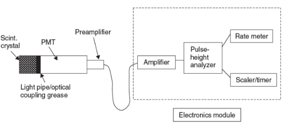
Figure 10 - Diagram of a scintillation detector ... 17
Figure 11 - Gamma ray production ... 20
Figure 12 - Subdivision of the gamma camera detector area for generating a digital image ... 24
Figure 13- Radiation profile and Relative FWHM for parallel-hole collimator ... 27
Figure 14 - Pixon reconstruction of a satellite survey scan ... 31
Figure 15 - Pixon reconstruction of a digital Nuclear Medicine planar image ... 32
Figure 16 -Pe fo a e of the Pi o ethod fo the Le a Matla i age ... 33
Figure 17 - Example of a Pixon image model and its correspondent graph structure ... 33
Figure 18 - Pseudo image and its correspondent Pixon map ... 34
Figure 19 - Pixon image reconstruction for a synthetic data set ... 35
Figure 20 - Block diagram of the steps of image reconstruction with Pixon map calculation . ... 36
Figure 21 - Simulated image reconstruction sequence ... 37
Figure 22 - Scheme of the Methodology used in this study ... 40
Figure 23 - Reconstruction parameters applied in the EPP software ... 42
Figure 24 - First question of the assessment form about metastatic lesion detection ... 43
Figure 25 - Second and third questions of the assessment form... 44
Figure 26 - Human skeleton diagram of the assessment form ... 44
Figure 27 - The two circular ROIs set in the images ... 45
Figure 28 - Combined image quality scores of the three observers by image type ... 49
Figure 29 - Combined diagnostic acceptability scores of the three observers by image type ... 51
xii
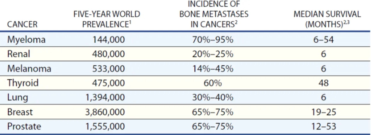
Table 1 – Incidence of bone metastases in different types of cancer...3
Table 2 – Number of scans diagnosed with metastatic bone disease ... 47
Table 3 – Number of cases scored according to the scoring form for the image quality ... 48
Table 4 - Number of cases scored according to the scoring form for the diagnostic acceptability ... 50
Table 5 –Interobserver agreement rates ... 53
Table 6 – Confidence of physicians in deciding whether an image represents metastatic disease. .... 54
xiii
Equation 1 – Signal-to-noise Ratio ... 28
Equation 2 – Acquired Image ... 29
Equation 3 – Image Reconstruction ... 30
Equation 4 - Image as an integral over a pseudo image ... 35
Equation 5 – Signal-to-noise Ratio (Methodology) ... 46
Equation 6 – Contrast-to-noise Ratio (Methodology)... 46
Monique Inácio Gomes 1
Introduction
In advanced oncologic conditions, the development of metastatic bone disease can be a common and severe complication. This condition is of particular interest in high prevalence carcinomas such as those in the breast and prostate, where bone is a common site for metastases.
Metastatic bone lesions put patients at high risk of skeletal complications, being also related to increased morbidity and decreased survival. Bone involvement in its clinical presentation may include pain and pathological fracture, contributing to a decreased in the quality of life.
There are several kinds of imaging available for the study of bone metastases. Each imaging technique depicts different aspects of tissues, influencing the appearance of the different malignant bone lesions. Thus, due to its great overall sensitivity, whole-body planar bone scintigraphy has been considered as the standard technique for bone metastases screening. This imaging technique provides the essential information concerning location, prognosis and evaluation of response to therapy.
Since pain is the most common presented symptom, patient care should never be forgotten. Diagnostic imaging procedures are not an exception. Thus, the professionals must look for the best techniques and methods that are suitable for each patient so the procedures can be successfully performed with minimal discomfort to the patient.
2
Monique Inácio Gomes 3
1.
Metastatic bone disease
In advanced oncologic disease, the development of metastatic bone disease can be a common and severe complication (Table 1). Bone is the most common site for metastasis in cancer and is of particular interest in breast and prostate cancers because of the prevalence of these diseases. Up to 70% of patients with these cancers develop this condition. The sternum is a common site for solitary skeletal metastasis in breast cancer, while the spine is the most common site of metastases in prostate carcinoma. Carcinomas of lung, kidney, thyroid and melanomas are other common tumours that metastasize to bone (1-5).
Bone lesions put these patients at high risk of skeletal complications. It is a condition associated with increased morbidity and reduced survival. The major complications related to bone involvement are severe and debilitating pain, spinal cord compression and pathological fracture, which contribute to the decreased quality of life of the patient (1,2,6).
Table 1 –Incidence of bone metastases in different types of cancer and the median survival (6).
1.1.
Pathophysiology of Bone Metastases
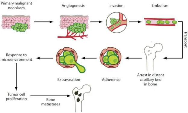
Monique Inácio Gomes 4 The mechanisms of bone formation and bone removal represent two tightly coordinated events of the normal remodelling cycle. They require synchronized activities of multiple cellular participants to ensure their sequentially occurrence at the same anatomical location in order to preserve bone mass. Consequently, this process depends on the orderly development and activation of osteoclasts and osteoblasts, involving series of highly regulated stages that depend on the interactions of these two cell line ages (6). In many advanced cancers, the skeleton, after the lungs and liver, is the third most common site of metastatic disease. The metastasis of tumour cells to the bone matrix involves a complex cascade of events (Figure 1) (6,8).
Figure 1 - Mechanism of tumour metastasis to bone (7).
This multistep mechanism involves a bidirectional interaction of the tumour cells with cellular elements in three different microenvironments: the site of primary malignant neoplasm, the transport and the bone microenvironment (2).
Monique Inácio Gomes 5
1.2.
Clinical Presentation
Metastatic bone disease is the cause of considerable morbidity in advanced cancer situations. The clinical presentation of this condition includes pain, pathological fracture, hypercalcemia and spinal instability with medullar compression (4,5).
1.2.1. Pain
The clinical presentation of metastatic bone disease is variable, but pain is the most common presenting symptom with either osteolytic or osteoblastic lesions. This condition is shown in 75% of patients during this type of clinical evaluation. Painless lesions are usually diagnosed during staging follow-up examinations to patients with a known history of carcinoma. Pain incompletely relieved by rest and night pain are not specific indications of metastasis, however they are typical symptoms. Furthermore, weightbearing bones may become symptomatic early in the course of disease, whereas bones such as the flat bones of ribs or sternum may remain asymptomatic until late in the disease, often until pathologic fracture occurs (8).
Different sites of bone metastases are related with distinct pain syndromes. Common sites of metastatic involvement associated with pain are the base of skull, vertebrae, pelvis and femur (3).
Lytic lesions with bone loss are usually associated with mechanical pain, whilst blastic lesions
a ause fu tio al pai th ough the loss of o e’s st u tu al i teg it . The tumour type,
lo atio , u e o size of etastases a d the patie t’s ha a te isti s a e ot o elated
with the presence of and the severity of pain. In general, this complaint develops gradually becoming progressively more severe. It can be divided into two types of pain according to the presented symptoms (continuous or incident pain) and the mechanism of the disease (primary or secondary). Primary pain involves bone resorption with disruption of skeletal architecture and microfracture. In contrast, secondary pain is characterized by nerve root infiltration or compression and reactive muscle spasm. For this reason, effective treatments are needed in orde to i p o e the patie t’s ualit of life (1).
1.2.2. Pathological Fracture
Monique Inácio Gomes 6 microfractures with consequent total loss of bone integrity. This type of fracture can occur spontaneously or after a minor injury, but it probability increases with the duration of the metastatic involvement (4,7).
1.2.3. Hypercalcemia
Hypercalcemia is defined as an elevation of plasmatic ionized calcium. In most cases, hypercalcemia is a result of bone destruction, and osteolytic metastases are observed in 80% of cases. This clinical feature occurs particularly in patients with breast malignancies, reflecting an association with the presence of liver metastases. The signs and symptoms of hypercalcemia are nonspecific, but normally include pain, fatigue, anorexia and constipation. If untreated, the result will be the deterioration of renal function and mental status (4,5).
1.2.4. Spinal instability with cord compression
Spine is the most common site of bone metastasis, making neurologic symptoms and spinal instability very frequent. Spinal instability will lead to mechanical pain with consequent impact on quality of life. Besides, spinal cord compression is referred as a medical emergency, which requires urgent evaluation and treatment. Local pain usually precedes radicular pain and may predate the appearance of other neurologic signs by weeks or months (4,5).
1.3.
Imaging Diagnosis
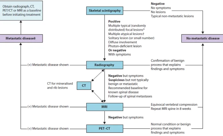
Monique Inácio Gomes 7 Figure 2 - Suggested algorithm of imaging studies for the osseous metastases (9).
Each imaging modality depicts different aspects of tissues. Hence, the appearance of the various types of bone lesions can considerably differ depending on the imaging technique (Figure 3) (10).
Figure 3 - Schematic bone structure and types of metastasis observed by a wide range of imaging modalities: Plain Radiograph (XR), Computed Tomography (CT), Magnetic Resonance Imaging (MRI),
Monique Inácio Gomes 8 1.3.1. Radiography
For some types of tumor, skeletal metastases are readily detected by radiological studies, forming an important aspect of clinical disease management. Thus, the radiological evaluation of focal symptoms is the first step in the assessment of suspected bone metastases, to visualize the painful area and access the structural integrity of the bone. However, it is not generally recommended as a screening method due to its poor sensitivity, which depends partly on lesion location (6,8,10).
Apart from the limited contrast for differentiation of the various soft tissues, the main disadvantage of this method is that anatomical structures are projected in one plan, leading to superimposition of a metastatic nodule with normal anatomic structures. Still, radiography may help to distinguish metastases from another conditions along with accessing the risk of pathological fracture (11).
Bone metastases are classified regarding the radiological classification of the observed changes in bone architecture, being usually described as: osteolytic, when bone destruction arises by the action of osteoclasts, as observed in breast cancer patients; osteoblastic, which are characterized by sclerosis, being predominant in prostate cancer conditions; or mixed, where both processes of resorption and formation occur at the same time. Although, it is important to remember that any cancer can appear in any pattern (3,4,6).
Radiographs are important for the interpretation of abnormal findings in the 99m-technetium bone scan, which should be correlated prior to confirming the diagnosis of metastatic bone disease (8).
1.3.2. 99m-Technetium Bone Scan
Since the introduction of 99m-technetium-based scan agents, the radioisotope bone scan has been the standard method for detection of skeletal metastases. This imaging method is more sensitive than radiography for detection of other skeletal sites of tumour involvement. Despite its low specificity and higher false-positive rates, it can detect these lesions earlier than plain films. False-negative findings can appear when pure osteolytic metastases are growing rapidly, when bone turnover is slow or when the site is avascular (7,9,10).
Skeletal scintigraphy (SS) is generally considered sensitive for detecting osteolytic or osteoblastic bone metastases on whole-body images. Moreover, the advantage of this kind of examination is not for diagnosis but rather for screening, as it is widely available and can produce quick images at reasonable cost (10).
Monique Inácio Gomes 9 1.3.3. Computed Tomography and Magnetic Resonance Imaging
Computed Tomography (CT) and Magnetic Resonance Imaging (MRI) can depict anatomic changes in more detail than SS (9).
CT is the study of choice when looking for bone detail and cortical damage since delineates cortex and can help the description of abnormal calcifications. Due to its technical advantages, CT is the most frequently used imaging diagnostic method for diagnosis, staging and detection of nodal and distant metastases, monitoring and follow-up in oncology (7,8,11).
For accessing bone metastases, MRI is preferable to CT due to its excellent soft-tissue contrast resolution, which allows better depiction of the marrow cavity and adjacent soft-tissues. MRI is often performed at the site of metastatic disease, being useful in cases in which the bone scan is negative but localized symptoms are present. This imaging technique is very sensitive to early marrow replacement and can locate metastases prior to their appearance on radiographs and CT scans, even with low resolution for bony anatomy. Through this study is also possible to distinguish between osteoporotic and malignant fractures (4,7,10).
If MRI and CT are not capable of detecting the disease and clinical suspicion of bone metastasis remains, the use of PET-CT is recommended (9).
1.3.4. PET-CT
Positron Emission Tomography (PET) is a tomographic technique that produces high-resolution images with three-dimensional distribution of radioactivity through the detection of high-energy photon pairs, emitted by the positron emitter labelled radioisotope. The glucose analogue 18-fluorodeoxyglucose (18-FDG) is the most commonly used tracer since the accumulation in tissue is proportional to the amount of glucose utilization. This radiopharmaceutical is wide used in oncology because of the high glucose uptake by many tumours (7,11).
In opposition to PET, CT generates tomographic images using an x-ray source. This imaging technique produces morphological and anatomic views with high resolution. Therefore, the information derived from CT can be used to increase the precision of localization, extent and characterization of lesions detected by 18-FDG PET (12).
Monique Inácio Gomes 10 morphology of the scintigraphic lesions through fusion of functional images with the anatomic dataset (7,12,13).
Monique Inácio Gomes 11
2.
Planar Nuclear Imaging
Nuclear Medicine is a diagnostic imaging modality in which information is obtained from the way the tissues and organs process radiolabeled compounds. The main purpose is the quantitative measurement of physiologic and biochemical characteristics of the body. This involves administrating a radioactive agent, which will be carried throughout the body by circulation and then taken up by organs where radioactive decay within the patient begins. This means that the unstable nuclei will decay to a more stable state by emitting energy in the form of radiation such gamma rays. Radioactive decay has applications in medicine for both diagnostic and therapeutic purposes (14-16).
The emitted radiation has high energy and can be detected and measured by suitable detection devices. The majority of those radiotracers used in diagnostic imaging are gamma emitters. That type of radiation can be detected by using imaging devices such gamma scintillation cameras, Single-Photon Emission Computed Tomography (SPECT) and PET scanners. In the particular case of planar scintigraphy, a simple gamma scintillation camera should be used (14,17).
2.1.
Gamma Camera
There are two types of nuclear imaging methods: single-photon imaging and PET. These two methods are distinguished by the physical properties of the administrated radioisotopes, which can radioactively decay by single or double-photon emission (14).
A gamma camera is a single-photon imaging technique, also referred as scintillation camera or Anger camera, being the primary imaging instrument used in Nuclear Medicine. The basic components of a gamma camera system are the collimator, the scintillation (or semiconductor) detector and readout electronics (Figure 4) (15-17).
Monique Inácio Gomes 12 Gamma cameras are used in both planar imaging and SPECT. Planar imaging produces a two-dimensional image of a three-two-dimensional object. Those images contain no depth information and some structures can be superimposed. To overcome this drawback, at least two views of the patient should be taken, depending on the procedure. For transaxial tomography (SPECT), the camera is rotated around the patient, acquiring multiple views from different angles. These projections are used to calculate the transverse activity distribution, applying suitable reconstruction methods. This procedure is performed with either rotating Anger cameras (with two or three camera heads) or specific ring or partial ring detector systems (18-20).
2.1.1. Physics and Instrumentation
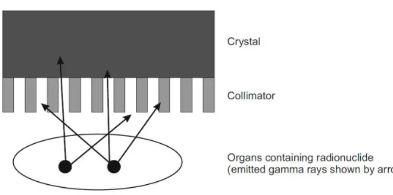
The principle of gamma cameras relays on the conversion of the photons emitted by the radionuclide in the patient into a light pulse and subsequently into a voltage signal (Figure 5). This signal is used to create an image which reflects the distribution of the radionuclide. Thus, scintigraphic instrumentation consists of scintillation crystals to convert gamma ray energy (photons) into visible light, specific light sensors, readout electronics and image processing units (17,18,19,21).
Figure 5 - Schematic of a gamma camera (16).
2.1.1.1. Collimator
Monique Inácio Gomes 13 Lead is usually the material of choice for collimators due to the combination of high density with high atomic number. High density materials are required due to the correlation between the attenuation coefficient, which must be high to ensure gamma photon absorption (17).
There are two basic types of collimators which can be defined as multihole and pinhole: A multihole collimator consists of a gamma radiation absorbing material with great abundance of holes distributed in a network. This configuration makes possible to select certain incident photons and to filter scattered rays that disturb the image formation. The barriers that confine those holes are named collimator septa. The septa must be thick enough to absorb most of the photons incident upon them. Therefore, collimators must have thicker septa for higher energy photons. Modifying a collimator should involve a compromise between spatial resolution and efficiency, since the thickness of the collimator, the diameter of the holes and the septa thickness are directly related to the image quality obtained (21,22).
Multihole collimators differ mainly in their geometry. The holes may be hexagonal, square or triangular, however, most state-of-the-art collimators have hexagonal holes and are usually made of lead foil. Besides, they can also be distinguished by the alignment of the holes in a parallel, converging and diverging manner (Figure 6) (17,21).
Monique Inácio Gomes 14 The parallel-hole (Figure 7) is the most widely used multihole collimator, which consists of
an array of parallel holes essentially perpendicular to the plane of the scintillation crystal, presenting a real-size image to the detector (orthogonal geometry). The type of parallel-hole collimator should be chosen according to the energy of the isotope being imaged: low energy (up to 150keV), medium energy (up to 280keV) and high energy (up to 364keV) (17,20).
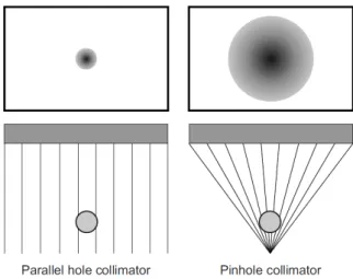
Figure 7- Main collimator configurations and their effect on the acquired image(16).
Thepinhole collimators are thick conical collimators with a single hole in the bottom centre, based on the obscure camera in which light rays pass through the pinhole aperture and are projected to form an inverted image on the scintillation crystal (Figure7). Since the radiation
pass though a small aperture, only a small percentage of the emitted photons can reach the crystal, resulting in reduced sensitivity. Another disadvantage of the pinhole is the distortion that occurs due to the finite size of the hole (20,22).
The pinhole collimators are routinely used for images requiring high resolution such small organs like the thyroid and certain skeletal regions (hips or wrists) as a result of the possibility of magnifying and improving spatial resolution (17,22).
2.1.1.2. Scintillation Crystal
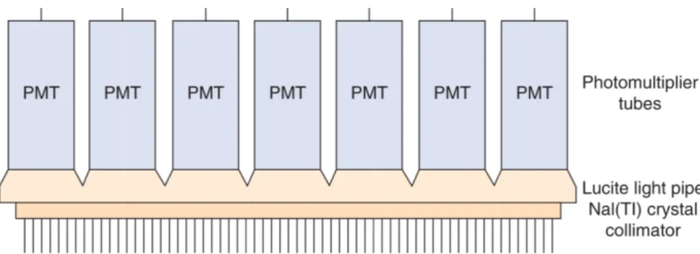
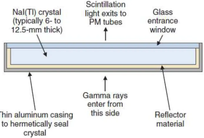
Monique Inácio Gomes 15 choice for single photon detection with energies of 70-360keV. Originally, the crystals had a circular cross section, but currently most cameras use a rectangular crystal 30-50cm wide and 0.9-1.2cm thick (Figure 8) (15,16,19).
Figure 8 - Schematic cross-section of a NaI(Tl) crystal for a gamma camera (21).
The purpose of a scintillator is to convert the gamma ray energy emerged from the patient into visible light after passing through the collimator. When ionizing radiation interacts with a scintillator, electrons are raised to an excited energy level. These electrons will then fall back to a lower energy state, producing a pulse of fluorescent light. The amount of light generated is directly proportional to the intensity of the absorbed energy, depending on the characteristics of the material (17,21).
Thus, scintillation materials must have specific proprieties such (21):
- High fraction of deposited energy that is converted into light - conversion efficiency; - Short decay time, so the light can be emitted promptly after an interaction;
- Transparency to its own emissions to avoid reabsorption of the emitted light;
- Large attenuation coefficient to improve detection efficiency (materials with higher densities and atomic numbers.
Monique Inácio Gomes 16 Although the energy resolution of a gamma camera is determined by the whole system, the light yield of the scintillation crystal is very significant, because it can improve the image contrast. The energy resolution expresses the ability of the detector to differentiate between gamma rays of closely spaced energies. NaI(Tl) has a moderate energy resolution, which is an important propriety that provides the means to discriminate against scattered radiation (15,19,22).
2.1.1.3. Photomultiplier Tubes
Having scintillation photons is not enough for the image formation. Thus, scintillation detectors incorporate a means of signal amplification that converts those photons into an electronic signal. This is accomplished by electronic devices referred as photomultiplier tubes (PMTs) (21,23).
Gamma cameras have an array of these devices located behind the scintillation crystal. They collect the light generated in the crystal, giving rise to electrical signals that contain information to determine the energy and position of interactions taking place in the crystal. Those interactions are processed individually, which requires the use of fast electronics and low dead time in the detector to allow high counting rates (22,23).
The number of PMTs is very important for the accurate localization of scintillation events, because the source can only be accurately tracked when considering the signals from other surrounding PMTs. Thus, the greater the number of PMTs, the greater the resolution. Moreover, the thickness of the crystal must be suited, because if the source is located far from the PMT (thicker crystals) the signal is weak and the location is not certain, degrading the spatial resolution (15,16,22).
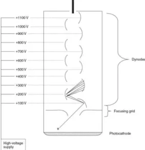
The main components of a PMT are: the photocathode, a focusing grid, several dynodes with a high voltage supply and the anode (Figure 9).
Monique Inácio Gomes 17 The photocathode is near the window of the PMT and converts scintillation photons into electrons. It is made of a photo emissive material, usually metal alloys that have extra electrons that will be released into the vacuum space of the PTM when interacting with scintillation photons.
The focusing grid will then accelerate the electrons toward the first dynode.
A series of dynodes multiply the electrons generated at the photocathode into a measurable electronic signal. They are also made of metal alloys, each one with higher potential than the last, emitting electrons toward each other.
At last, the anode collects the produced electrons from the final dynode and gives off a voltage signal (22,23).
2.1.1.4. Associated Electronics
When a gamma ray interacts in the scintillation crystal, scintillation photons are emitted. Those, in turn, cause the emission of a few electrons at the photocathode of the PMT that will be converted to a measurable electronic signal at the anode of the PMT. Although the signal given off by the PMT anode is measurable, it is considered small. Thus, a preamplifier and an amplifier are used to increase the output signal by a variable amount. Besides, they are also useful to shape and shorten the pulse in order to provide a series of discrete pulses that is easier to analyze (21).
The PMT signals are converted into a numeric magnitude by analog-to-digital converters, so that the energy and positions can be calculated by computer algorithms that can accurately model those signals with the source position (Figure 10) (19).
Monique Inácio Gomes 18 2.2. Measures of Performance
A scintillation camera has two types of measures of performance: extrinsic and intrinsic. Extrinsic measurements are calculated with the collimator attached to the detection system. On the other hand, if the collimator is not present, the measurements are called intrinsic. Extrinsic measurements give the best indication of clinical performance while intrinsic measurements are more useful to compare the performance of different cameras (15).
2.2.1. Resolution
Resolution is one of the common performance parameters for gamma cameras. It can be referred as spatial or energy resolution (17,21,23):
- Spatial resolution is a measure of the ability of an imaging device to separate objects close together in space. It reveals the accuracy of the system to depict spatial variations in activity concentration and to distinguish as separate radioactive objects in close proximity;
- Energy resolution is the ability to discriminate between light pulses induced by gamma photons of differing energies. It evaluates how well a detector distinguishes between gamma rays of closely spaced energies.
Resolution can be increased by using more, smaller holes or by making the collimator longer. This will, however, reduce the fraction of photons detected by the system due to the increased amount of lead in the collimator (20).
2.2.2. Sensitivity
This parameter is defined as the overall ability of the system to detect the radioactive emissions from a source. Thus, it increases with the fraction of the emissions that are detected. Sensitivity can be increased for multihole collimators by increasing the size or shortening the length of each hole. However, this will occur at the expense of resolution. Thus, a balance between these two parameters needs to be done (20).
2.2.3. Uniformity
Monique Inácio Gomes 19 tested intrinsically and extrinsically. The intrinsic measurement is performed using a point radionuclide source in front of the camera without collimators, whilst system uniformity is assessed by placing a uniform planar radionuclide source in front of the collimated camera. The acquired images are then quantitatively analyzed by a computer in order to obtain the results (17,21).
2.2.4. Dead Time
If scintillation events occur too close together in time, the electronic system can be unable to count all the events that reach the crystal. The time after an event during which the system is unable to respond to another event is referred as the dead time, being strongly related to the count rate of the detector (24).
2.3.
Bone Scintigraphy
Bone scintigraphy or SS is one of the most common procedures in routine Nuclear Medicine. It is a diagnostic study that aims the evaluation of the distribution of active bone formation within the body (25,26).
With this technique is possible to obtain whole-body or limited bone scintigraphic images, according to the indications for the examination. In whole-body procedures, planar images of the entire skeleton are acquired, including anterior and posterior views (22).
The radionuclide bone scan is an extremely sensitive method for demonstrating a variety of skeletal disorders, allowing earlier diagnosis or demonstrating more lesions than conventional radiological techniques. The main indications for referral are: detection and follow-up of metastatic disease, trauma difficult to access on radiographs, sport injuries, evaluation of prosthetic joints and rheumatologic disorders (24).
2.3.1. Radiopharmaceutical – 99mTc
Technetium (Tc) is a transition metal that, in the form of one of its isotopes Tc-99m, is the most widely used radioisotope in Nuclear Medicine. It has a half-time period of 6 hours, where 87% of the decays produce 140keV gamma photons (Figure 11). This property makes
99mT suita le fo i agi g ith ga a a e as, ei g also safe ega di g the patie t’s
Monique Inácio Gomes 20 Figure 11 - Gamma ray production. The atom passes from a high-energy state to a low-energy state,
releasing a gamma photon with a peak energy of 14keV (27).
At the present, phosphate analogues labelled with 99mTc are the radiopharmaceuticals of choice for SS. They are widely used on account of the good localization in the skeleton as well as the rapid clearance from soft tissues. Thus, they can provide a better image of bones due to the lower blood and tissue concentrations, giving a higher ratio of bone to tissue (25,28).
2.3.1.1. Mechanism of Accumulation
Two major factors control the accumulation of the radiotracer in the bone, specifically blood flow and extracting efficiency. The average administrated activity for a single injection should be around 500MBq, corresponding to an effective radiation dose of approximately 3mSv. The uptake of any agent in the body depends on the blood supply, the capillary to bone transfer and the degree of osteoblastic and osteoclastic activity. After the radiopharmaceutical injection, about 50% of the activity accumulates in the skeleton according to the following steps (17,25,28,29):
- Generally, the clearance of 99m-technetium-labeled radiopharmaceuticals from the vascular compartment is fast, with half-times of 2-4 minutes;
- The peak uptake in the bones is variable, but is normally reached at 1 hour after injection;
- The bone to background ratio varies with the different clearance and uptake rates of other tissues, having its maximum later at 4-6 hours;
Monique Inácio Gomes 21 2.3.1.2. Patient Preparation
There is no special patient preparation concerning the bone scintigraphy. At the beginning, patients need to have a complete understanding of the procedure, including the reason of the delay between radiopharmaceutical administration and scanning, which is approximately 3 hours to achieve good bone accumulation and a low soft-tissue level of the radiopharmaceutical (23).
Unless contraindicated, patients should be well hydrated, being instructed to drink water between the time of injection and the time of delayed imaging. It will aid the clearance of the radiopharmaceutical from the body. Furthermore, voiding frequently is also important to reduce the radiation dose to the bladder and the activity on the bladder during the exam. Thus, the patient should also be requested to urinate immediately before the scan. During this phase, contamination with urine must be avoided, because it can lead to false-positive findings on the study (24).
It is also essential to remember that before considering submit a patient to a scintigraphic procedure, some precautions need to be taken: in case of pregnancy, a clinical decision is necessary to weigh the benefits against the possible harm; breast-feeding should be discontinued at least for 4h and for 24h post injection when possible (23).
2.3.1.3 Imaging Metastatic Disease
The ability to image the entire skeleton makes planar bone scan unique when compared with other diagnostic techniques, resulting in a fast, cost-effective survey of the skeletal system. For this reason, the standard technique of bone scintigraphy in oncology is considered to be the whole-body scan. The overall sensitivity for detecting bony metastases is 95%, with a false-negative rate of 2% to 5% (28,30).
In the evaluation of oncological patients, SS provides the essential information related to the sites of osseous metastases, their prognosis and evaluation of osseous tumour response to chemotherapy and radiation therapy (25).
Monique Inácio Gomes 22 Most metastases are multiple and relatively obvious but the interpretation may sometimes be difficult because of the single lesions, which have high false-positive rate. In general, bone metastases are observed as an increased uptake. The inherent osteoblastic response induces the deposition of radiotracer, generating a positive finding on the image. The usual pattern of metastatic bone disease is multiple focal lesions all over the skeleton, with the greatest involvement usually in the axial skeleton. Despite the high sensitivity of this technique, tracer uptake in bone scan is not specific for most metastatic bone disease (4,8,10,20,29). Since metastases are usually located in the bone marrow, it is not the metastasis itself that shows up on the bone scan, but the reaction of the bone to the expanding malignant bone marrow. The lesions have cold signal when they are highly aggressive with fast expanding, since there is not enough time for the bone to respond and the regional blood flow may be damaged to such extent that the tracer cannot be delivered (26).
If a diffuse involvement of the skeleton by metastases is noticed, it may initially appear as though there has been remarkably good, relatively uniform uptake in all bones. This occurrence is commonly known as a superscan. If this finding is induced by metastases, a significantly decrease renal activity with diffusely increased activity will be noted throughout the axial skeleton. This condition is commonly a result of prostatic cancer, but other tumours such breast cancer and lymphoma may also be the source of this appearance (24).
Follow-up scans of advanced breast and prostate cancer should be interpreted with caution. When imaging bone tumour response on a planar bone scintigraphy, findings usually emerge as a decreased intensity of radionuclide uptake by the metastatic foci. However, in the first 3 months of chemotherapy, a favourable clinical response by focal bone metastases may result in healing and increased uptake, which is a good prognostic sign. Disease progression is usually suggested by bone lesions that appear 6 months or later after treatment (24).
2.3.1.4. Imaging Technique
According to the procedure guidelines of the European Association of Nuclear Medicine (EANM), image acquisition for bone scintigraphy should be performed using a single or a double-head gamma camera, equipped with a low-energy, high resolution collimator, which is suitable for the 140keV photopeak of 99mTc (23).
Monique Inácio Gomes 23
2.4.
Pitfalls and Artefacts
There are several sources of error in bone scintigraphy. They can be artefacts related to the patient or to the technique itself.
Technical artefacts include equipment, radiopharmaceutical and image processing problems due to (28,32):
- Poor quality control and calibration;
- Inadequate preparation of the radiopharmaceutical that modifies biodistribution and compromises the diagnostic quality of the images;
- Extravasation at the site of injection, the most common artefact on bone scintigraphy;
- Source-to-detector distance greater than necessary; - Imaging at wrong timing.
The main patient-related artefacts can be described as (28,32): - Patient movement;
- Urine contamination;
- Prosthetic implants or other attenuating artefacts that may obscure normal structures, inducing photon-deficient areas;
- Homogeneously increased bony activity;
- Restraint artefacts caused by soft-tissue compression; - Pubic lesions obscured by underlying bladder activity; - Renal failure.
Moreover, there are several pitfalls that can originate misinterpretations of the image findings (28):
- Some aggressive or purely lytic metastases may not produce a visible osteoblastic response. Thus, they will appear as purely cold lesions, making more difficult their identification on a routine whole-body bone scan;
- If the bone scintigraphy is used for the assessment of treatment response but performed very soon after the treatment, it may be difficult to differentiate a flare response from tumour progression;
Monique Inácio Gomes 24
3.
Reducing Scan Time in Bone Scintigraphy
To generate an adequate diagnostic image in Nuclear Medicine, an appropriate balance between image quality and radiation dose is required. According to this, it is desirable to reduce radiation dose as well as the scanning time. For clinical practice it is important to obtain an accurate clinical diagnosis with collection of a minimum number of counts (33). Since Nuclear Medicine images suffer from relatively high levels of noise and low SNR. Noise reductions can be achieved by increasing radiation dose or image acquisition times or even by filtering the image with processing and post-processing techniques. Thus, some practical steps can be considered to improve diagnostic values in Nuclear Medicine diagnostic imaging (27,34,35,36):
- Radiopharmaceutical dose: As mentioned above, an accurate diagnosis suggests using the minimum radiopharmaceutical dose, suitable for each procedure (particularly in the case of repetitive imaging). This means that reducing the administered radiopharmaceutical will generate images with decreased SNR. On the contrary, despite the fact that increasing the administered radioactivity increases the number of counts in the image, it could lead to higher radiation dose to patients; - Pixel size: A digital image is one in which events are lo alized o i ed ithi a
grid comprising a finite number of discrete picture elements referred as pixels. For a gamma camera, the detector area is divided into the desired number of pixels, where each pixel corresponds to a range of possible physical locations within the image (Figure 12). Digital images can be characterized by their matrix size, which is the
number of pixels presented by the image matrix. This parameter affects the degree of spatial detail that can be presented, with larger matrices (smaller pixel size) providing more image detail. On the contrary, increasing pixel size could lead to noise reduction with increased SNR, but it would also induce reduced resolution due to the smaller amount of collected signal;
Monique Inácio Gomes 25 - Acquisition time: Extending the duration of the procedures increases the number of collected counts. However, this is not tolerated by many patients and this could also result in the appearance of motion artefacts since patients have tendency to move when experiencing discomfort, due to pain for example. In this field, there is always a compromise between image quality, workflow economics, patient safety and patient comfort;
- Reconstruction methods: An alternative option is to apply reconstruction techniques that allow increases in spatial resolution, enhancing the signal. However, this process is highly influenced by noise due to random measurement errors, which cannot be predicted. Thus, one needs to assume that they are random realizations of some parental statistical distribution in order to find a solution for the image model. Moreover, noise effects can be reduced by using appropriated techniques for statistical filtering.
Digital image processing makes possible to reconstruct images acquired from non-ideal conditions, obtained from real-world instruments. As a result, information present but hidden in the data can be revealed with less blur and noise. This means that low-count, noisy images can have their quality improved, allowing images with a lower number of counts to be acquired (37,38).
Presently, the pressure to reduce injected activities has reached new levels, making more rapid scanning desirable as well. Besides, due to their debilitating condition, patients submitted to whole-body bone scans can experience pain and anxiety during the examination. Because of the long scanning times in use for standard procedures (about 30 minutes) it is even more difficult to acquire images with sufficient image quality (33).
Thus, the reduction of acquisition time together with suitable image processing methods may be an appropriate method for noise reduction. Hence, the best technique must be found in order to increase confidence in the diagnosis of features observed in the image originally acquired with modified parameters (29).
Monique Inácio Gomes 26
4.
Processing Scintigraphic Images
Digital image processing is a robust means by which the underlying images hidden in blurry and noisy data can be revealed. It has been widely developed, providing high-quality reconstructions of blurry and noisy data collected by an extensive variety of sensors. Thus, it is mathematically possible to reconstruct the underlying image from non-ideal data collected from real-world mechanisms, so that the hidden information can be revealed with less blur and noise (38,39).
The use of digital processing techniques can be used for image improvement, having many applications in space imagery and medical research. It involves operations that improve the quality of an image as perceived by a human or a machine, applying a broad set of algorithms and tools to repair, analyze, develop and visualize images. The need for implementation of image processing techniques will depend on the physical properties of the systems that describe their quality of response (22,39).
4.1.
Image Quality in Nuclear Medicine
Image quality can be defined by the capability of the system to detect relevant information, being related to the accuracy with which an image represents the imaged object. The quality of medical images depends on its information content and how accessible the information is, defined as its usefulness in determining an accurate diagnosis. As mentioned in the previous chapter of this document, there are several concepts used to describe imaging systems in terms of their quality of response, being referred as spatial resolution, contrast and noise. Those parameters are also recognized as the essential elements of image quality in Nuclear Medicine, being related to the diagnostic utility of the image (21,22).
Despite the fact that the mentioned characteristics used for Nuclear Medicine image quality describe three different aspects, they cannot be treated as completely independent parameters, because improving one of them may induce deterioration of one or more of the others (21).
Monique Inácio Gomes 27 4.1.1. Spatial Resolution
Spatial resolution is a property that describes the ability of an image system to accurately depict objects in the two or three spatial dimensions of an image. Technically, the spatial resolution of a digital image is regulated by two factors: the resolution of the imaging device itself and the size of the pixels used to represent the image in its digital format. Consequently, despite the higher amounts of noise, a smaller pixel size can exhibit more image detail. However, beyond a certain point there are resolution limitations related to the imaging device, allowing no further improvements on the acquired image (21,28).
Nuclear Medicine images have somewhat limited spatial resolution, at least when compared with radiological images. As mentioned in the previous chapter of this document, a number of factors contribute to the lack of sharpness in these images (21).
The evaluation of spatial resolution can be performed by subjective or objective means. A subjective evaluation involves visual inspection of the images. However, different observers may provide different interpretations, making the estimation of image quality difficult and subjected to inter-observer variability. One conceptual way of understanding and measuring the spatial resolution of a detector system in the spatial domain is to stimulate the detector with a single point source and then observe the way it responds (21,27).
4.1.2. Point Spread Function
The image produced by a detector system from a single point input is referred as the point spread function (PSF). It expresses the blurring properties of the imaging system, describing the imaging system response to a point input (Figure 13).
Monique Inácio Gomes 28 The full width at half maximum (FWHM) of the generated profile is used to characterize the
olli ato esolutio . Be ause P“F’s of diffe e t shapes a ha e the sa e FWHM, it o l
provides a partial specification of the spatial resolution characterization. However, the FWHM is considered as an useful parameter for general comparisons of imaging devices and techniques (21,27).
On other words, the PSF expresses the performance of medical imaging devices in terms of sensitivity and spatial resolution by means of a function that describes the image when the object is a point. It describes how a photon originating at position in the image plane ends up at position in the focal plane. In general, the PSF varies independently with respect to both and , because the blur of a point source can depend on its location in the image (22,28).
4.1.3. Signal-to-Noise Ratio
The signal-to-noise ratio is an expression used to describe the power ratio between the signal (significant information) and the background noise. In one imaging application view, these quantities would be a fixed known activity concentration and the standard deviation of its inherently fluctuating measured values attributable to the imaging protocol (31).
Thus, measuring the amount of noise by its standard deviation, , one can define the SNR as (30):
(1)
4.1.4. Contrast
Monique Inácio Gomes 29 4.1.5. Noise
A common form of noise consists of significant undesirable random fluctuations in pixel values that are superimposed on the ideal true values associated with objects being viewed. This phenomenon is commonly due to the random nature of the detection process and is visually perceived as graininess (31).
On a first approximation, one can write the acquired image in the following form (30):
(2)
Where is the observed value, ould e the t ue alue at pi el , namely the one which would be observed by averaging the photon counting, and is the noise perturbation. The last parameter corresponds to small random pixel variations in the value superimposed on a true mean value from uptake signal (40,41).
Images may be subjected to noise and interference from several sources. It can be caused by the randomness in the radioactive process as well as by some features of image reconstruction. Consequently, it creates problems for the subsequent process of reading and interpreting such images. Noise effects can be reduced by statistical filtering techniques or by a different approach, the application of noise cleaning techniques. However, image noise reduction (denoising) has remained a main problem in the image processing field (39,42,43). The main challenge is sensitivity to noise measurement in the input data, which can be strongly magnified, resulting in large artefacts in the reconstructed image. The answer to this difficulty is to restrict the permitted images. Progressively most sophisticated restrictions have been developed, imposing a variable degree of restriction across the image. However, the most consistent reconstruction method is considered the most conservative one, which restricts the permissible image modules (32).
Monique Inácio Gomes 30
4.2.
Image Reconstruction
The massive production of digital images has widely increased the need for efficient image reconstruction methods. Since images are often generated in poor conditions, an image improvement is always desirable (30).
Image reconstruction for data acquired with linear detectors often becomes a matter of inverting an integral relation of the form:
(3)
Where:
– Array of data points;
– PSF;
– Required underlying image model;
– Noise.
In general, the imaging problem may be defined in a space with an arbitrary number of dimensions ( , ). If is the PSF for a 2D imaging system and is symmetric about a central axis, the response of the system can be totally described by the curve in an axial plane that intersects . The system sensitivity will be proportional to the volume under the surface . A perfect imaging system presents a point for each object point, meaning that the response is ideal (17).
Monique Inácio Gomes 31
5.
Pixon Method
The Pixon method represents an innovative way of modelling an image in terms of its information content, allowing new competences in the fields of image reconstruction and data compression. As it offers versatile commercial software for a wide range of applications together with strong benefits to all kinds of imaging systems, the areas of medical imaging are not an exception (34).
Since image reconstruction is an important application in a number of fields, the Pixon method promotes medical images enhancement by (37):
5. Improving sensitivity, reducing false negatives; 6. Eliminating image artefacts, reducing false positives; 7. The reduction of patients risks from ionizing radiation;
8. Reducing effects due to patient motion by reduction of image acquisition time; 9. Reducing total cost of medical care.
The Pixon method is a high-performance image reconstruction technique that searches for the smoothest image statistically consistent with the raw counts. This concept was developed by Pina and Puetter in 1993 to restore astronomy images, with the purpose of eliminate problems with existing image reconstruction techniques, particularly signal-correlated residuals (Figure 14). The goal of this technique is to construct the simplest model
for the image that is consistent with the data. As it is the simplest model, the derived image would be artefact free with no spurious sources. Consequently, Pixon method seeks for minimum complexity for the plausible model of the image, which enables an efficient representation of the image as well as the best way to separate signal from noise. It has been applied to many fields, including medical image reconstruction (44-48).
Figure 14 - Pixon reconstruction of a satellite survey scan. The resolution of the reconstructed image (on the left) is 20 times finer than the raw scan (on the right) and the sensitivity is improved by a
Monique Inácio Gomes 32 The Pixon concept is based on a nonlinear image reconstruction algorithm that increases linear spatial resolution by a factor of a few and sensitivity by an order of magnitude or more. Linear processing techniques are applied on images with continuous noise, however, they tend to provide too much smoothing. Despite the fact that they are more compact and less computationally demanding, they have poor noise propagation properties. In contrast, nonlinear techniques have been considered as the most successful modern methods of image reconstruction. This method is more complex, however, it often provides a better trade-off between noise smoothing and retention of fine image detail due to better control over the propagation of noise (39,44,49).
Pixon noise-reduction method provides statistically unbiased photometry, since it performs a robust rejection of spurious sources by using the local information content, preserving statistically justifiable image features without generating artefacts. It can be applied on planar Nuclear Medicine images with known Poisson noise characteristics with the following goals: increase sensitivity for detection of lesions of decreased activity-to-background ratio; reduce acquisition time; and reduce patient dose (Figure 15) (29).
Figure 15 - Pixon reconstruction of a digital Nuclear Medicine planar image. The raw image is significantly blurred with noise artefacts from photon counting statistics. On the contrary, the
reconstructed image has improved resolution and reduced noise, enhancing the diagnostic capabilities (34).
Monique Inácio Gomes 33 Figure 16 - Pe fo a e of the Pi o ethod fo the Le a Matlab image (34).
Instead of representing the images with pixels of a constant size, Pina and Puetter introduced an image model where the size of the pixels varies locally according to the information density in the image, generally referred as pixons or degrees-of-freedom. Each Pixon represents a degree of freedom that is determined using a larger fraction of the data and so is determined more accurately. A map of the Pixon sizes is called an image model (Figure 17). With this, the Pixon method aims to find the best match between the image and
its image model that is consistent with the data and can represent the structure in the image by the smallest number of pixons. This generally results in superior photometric and positional accuracy and, since the minimum number of parameters are used, the data cannot be over-fitted (48,50).
Figure 17 - (a) - Example of a Pixon image model; (b) - Its correspondent graph structure (35).