U
NIVERSIDADE DE
L
ISBOA
Faculdade de Ciˆencias
Departamento de Inform´atica
SECURE GPS CLOCK SYNCHRONIZATION IN
SMART GRIDS
Radu Petrut¸ Onica
Dissertac¸˜ao orientada pelo Prof. Doutor Nuno Fuentecilla Maia Ferreira Neves
e co-orientado pelo Prof. Doutor Ant´onio Casimiro Ferreira da Costa
DISSERTATION
MESTRADO EM SEGURANC
¸ A INFORM ´
ATICA
Acknowledgements
Firstly, I would like to express my sincere gratitude to my advisor Prof. Nuno Neves as well as my co-advisor Prof. Ant´onio Casimiro for the continuous support of my Mas-ters thesis, for their patience and motivation.
I am sincerely grateful to Rodrigo, Soraia and Ricardo for all their support during the writing of this dissertation as well as the motivation they gave me, to help me over-come the hardest obstacles I faced. A huge thanks to all my colleagues, Bernardo, Pedro, Miguel, Tiago, Maneca and Andr´e for the all the memorable moments and all the fun we had this past year.
Lastly I would like to thank my family and especially my sister for always encoura-ging me and giving me motivation to move forward both throughout this thesis and my life in general.
Resumo
As smart grids resultaram da integrac¸˜ao da rede el´etrica atual no mundo digital. Isso traz v´arias vantagens `as redes el´etricas, como uma instalac¸˜ao, configurac¸˜ao e manutenc¸˜ao mais simples e eficiente, mas tamb´em a f´acil integrac¸˜ao na rede de novas tecnologias. En-quanto as redes el´etricas continuam a crescer em dimens˜ao e complexidade, elas tornam-se mais importantes para a sociedade e subtornam-sequentemente mais sujeitas a ataques distin-tos. Alguns dos objetivos mais importantes da smart grid s˜ao: acomodar uma grande variedade de tecnologias de produc¸˜ao de eletricidade como a e´olica, solar e geot´ermica; ser resiliente a ataques f´ısicos e ciber-ataques; ter mecanismos de detec¸˜ao, an´alise e res-posta autom´atica a incidentes; dar mais poder ao consumidor final sobre como e quando a energia pode ser comprada ou consumida.
Para implementar actividades relacionadas com a monitorizac¸˜ao do estado da smart grid, v´arios componentes especializados s˜ao geograficamente distribu´ıdos pela rede. Um dos dispositivos cr´ıticos ´e o Phase Measurement Unit (Unidade de Medic¸˜ao de Fase) (PMU). Este dispositivo ´e usado para estimar o estado da smart grid num determinado momento, recolhendo v´arias m´etricas sobre a qualidade do sinal el´etrico. Para se con-seguir criar uma imagem geral da rede inteira, todos estes dispositivos necessitam de ser sincronizados no tempo, assegurando assim que as medic¸˜oes s˜ao efetuadas aproximada-mente no mesmo instante.
A sincronizac¸˜ao do tempo desempenha um papel crucial na estabilidade e no fun-cionamento correto de todos os componentes da smart grid. Dada a importˆancia da sincronizac¸˜ao de tempo, e a falta de qualquer tipo de protec¸˜ao nas soluc¸˜oes atuais, este sistema torna-se num alvo potencial para atacantes.
Em conformidade com os standards, a precis˜ao dos rel´ogios dos PMU’s devem ter um erro m´aximo na ordem dos 30 µs. Isso garante que a informac¸˜ao recolhida sobre o estado da smart grid ´e v´alida. Hoje em dia este requisito ´e satisfeito usando equipamentos GPS em cada s´ıtio onde se encontra um PMU. Quando o GPS foi concebido, n˜ao se pensou que podia vir a ter o sucesso e o impacto atual e, portanto, assegurar a sua seguranc¸a n˜ao foi um ponto importante. Ao longo do tempo passou a ser usado em infraestruturas cr´ıticas, o que introduz eventuais problemas graves de seguranc¸a. As smart grids s˜ao uma destas estruturas cr´ıticas onde o GPS est´a a ser usado sem qualquer tipo de protec¸˜ao. Atualmente existe tamb´em uma vers˜ao segura do GPS que ´e empregue pelas forc¸as militares. Os
dispositivos que conseguem decifrar este sinal s´o est˜ao dispon´ıveis ao ex´ercito. Por al´em disso, todos os detalhes sobre o funcionamento do algoritmo de cifra s˜ao mantidos em segredo.
Ao longo dos anos foram desenvolvidos v´arios tipos de ataques ao GPS. O mais b´asico ´e o Blocking que consiste simplesmente em impedir a comunicac¸˜ao entre a antena do recetor e o sinal GPS. Isso pode ser conseguido de uma maneira t˜ao simples como tapar a antena com um bocado de metal. Um ataque que tenta tamb´em quebrar a ligac¸˜ao com o sat´elite ´e o Jamming. A ideia deste ataque ´e introduzir ru´ıdo suficiente para que o recetor n˜ao consiga distinguir o sinal original. Estes dois tipos de ataques s´o conseguem perturbar o funcionamento do recetor GPS. Um tipo de ataque mais potente ´e o Spoofing. Este ataque consegue modificar o sinal original vindo do sat´elite de forma a enganar o recetor. Assim ´e poss´ıvel fazer com que o recetor GPS mostre uma posic¸˜ao ou tempo incorretos. Nesta dissertac¸˜ao tamb´em foi analisada uma evoluc¸˜ao deste ataque que tem como alvo a alterac¸˜ao ileg´ıtima dos dados contidos no sinal. Isso pode fazer como que o recetor falhe ou deixe de poder ser usado.
Os algoritmos de sincronizac¸˜ao de rel´ogios existentes hoje em dia, nomeadamente o Network Time Protocol (NTP)e o Precision Time Protocol (PTP), n˜ao s˜ao suficientemente robustos, em termos de seguranc¸a ou precis˜ao, para serem utilizados na smart grid. O NTP foi concebido para a sincronizac¸˜ao de rel´ogios em redes de grande escala mas n˜ao consegue fornecer a precis˜ao necess´aria para os requisitos da smart grid. Por outro lado temos o PTP que consegue atingir uma precis˜ao na ordem dos nanosegundos em certas condic¸˜oes, mas ´e muito sens´ıvel a atrasos e oscilac¸˜oes na rede. Isso faz com que o PTP s´o consiga garantir uma precis˜ao de tempo na ordem dos nanosegundos em redes de pequena escala. A smart grid usa uma rede de alta velocidade com relativamente pouco tr´afego, o que torna o PTP uma poss´ıvel soluc¸˜ao para algumas partes dessa rede. Em termos de seguranc¸a, o PTP n˜ao est´a preparado para ser utilizado num ambiente t˜ao cr´ıtico como a smart grid, sendo suscet´ıvel a ataques.
O foco desta investigac¸˜ao ´e encontrar um algoritmo resiliente a faltas, capaz de satis-fazer os requisitos de sincronizac¸˜ao de tempo necess´arios para o correto funcionamento da smart grid. Foi desenvolvida uma soluc¸˜ao baseada no PTP, que consegue cumprir os requisitos de precis˜ao temporal na smart grid e tamb´em consegue mitigar todos os tipos de ataques ao GPS que foram identificados. Para al´em disso, a soluc¸˜ao tamb´em permite reduzir o n´umero de recetores de GPS necess´arios para o funcionamento correto da smart grid.
Palavras-chave: Smart Grid, GPS, Sincronizac¸˜ao de relogios, Seguranc¸a
Abstract
Smart grids resulted from the integration of computer technologies into the current power grid. This brings several advantages, allowing for a faster and more efficient deployment, configuration and maintenance, as well as easy integration of new energy sources (e.g., wind and solar). As smart grids continue to grow in size and complexity, they become subject to failures and attacks from different sources. Time synchroniza-tion plays a crucial role in the stability and correct funcsynchroniza-tioning of many grid components. Considering how sensitive time synchronization is, the tight restrictions imposed for cor-rect operation and the lack of any kind of protection, makes this service a potential prime target for attackers. Today most of the time synchronization requirements are met using relatively expensive GPS hardware placed in some locations of the smart grid. When GPS was first devised, nobody could have predicted the success and the impact that it would have and therefore, security was never an important concern. Through the years, it slowly gained entrance into more critical systems, where it was never intended to be used, which can lead to serious security problems. The smart grid is just one of these critical systems where GPS is being employed without any kind of protection. The focus of this research is trying to solve this problem, by proposing a more secure and robust clock synchroniza-tion algorithm. A solusynchroniza-tion based on the Precision Time Protocol (PTP) was developed that manages to fulfill the time synchronization requirements of the smart grid and is also capable of mitigating all types of identified GPS attacks. As an added benefit, the solution may also reduce the number of GPS receivers necessary for the correct operation of the smart grid, contributing to decrease costs.
Keywords: Smart Grid, GPS, Time synchronization, Security
Contents
List of Figures xvii
List of Tables xix
1 Introduction 1 1.1 Requirements . . . 4 1.2 Contributions . . . 4 1.3 Timeline . . . 5 1.4 Thesis outline . . . 8 2 Context 9 2.1 The Smart Grid . . . 9
2.2 Global Positioning System . . . 11
2.2.1 GPS Attacks . . . 13
2.3 Precision Time Protocol . . . 15
2.3.1 PTP Devices . . . 16
2.3.2 Message Exchange . . . 16
2.3.3 Network Delay and Clock Offset . . . 18
2.3.4 Best Master Clock Algorithm . . . 20
2.3.5 PTP security . . . 21
3 Fault Tolerant PTP 23 3.1 Overview . . . 23
3.2 Attack Model . . . 24
3.3 System Architecture . . . 26
3.4 Solution . . . 27
3.4.1 Crash failure detection . . . 29
3.4.2 Byzantine failure detection . . . 29
3.4.3 Modified Best Master Clock Algorithm . . . 31
4 Implementation and Experimental Evaluation 33 4.1 Implementation . . . 33 4.2 Testing Platform . . . 39 4.3 Results . . . 39 5 Conclusion 43 Bibliography 48 xiv
List of Figures
1.1 SDR based GPS receiver. . . 2
1.2 Simple NTP Network. . . 3
1.3 Gantt chart representing the initial thesis work plan. . . 5
1.4 Gantt chart representing the final thesis work plan. . . 7
2.1 Smart grid topography [1]. . . 10
2.2 Trilateration process used to calculate current position using GPS. . . 13
2.3 Simple PTP Network (M/S means that the communication port acts as master/slave). . . 15
2.4 PTP Message Exchange. . . 17
3.1 Boundary Clock as originally defined by PTP. . . 23
3.2 Boundary Clock with the proposed modification. . . 24
3.3 System Architecture. . . 26
3.4 Boundary Clock state during normal operation. . . 27
3.5 Boundary Clock state after an attack was detected. . . 28
4.1 Ptpd2 class diagram. . . 34
4.2 Ptpd2 clock servo diagram. . . 36
4.3 Modified ptpd2 class diagram. . . 37
4.4 Crash fault detection. . . 39
4.5 Gradual Clock Skew. . . 40
4.6 Clock offset during Delay Attack. . . 41
4.7 Packet Delay Attack. . . 41
List of Tables
2.1 PTP Message types. . . 18
Chapter 1
Introduction
The smart grid represents the evolution and integration into the digital world of the current electrical grid. Information technologies are used to improve the way the electric genera-tion and distribugenera-tion is currently done, making it more efficient, reliable and sustainable. The smart grid will support better automation, management and coordination between the end-user and the producer. Advantages include advanced monitoring that can accurately identify and take measures to mitigate failures and attacks. Self-healing technologies can be implemented that will allow the grid to solve problems without the need for on-site verifications or any kind of human intervention.
This increase in interaction between production and consumption, as well as the sheer complexity demanded by such a network, leads to a set of new challenges and security problems. User privacy becomes a real concern because of the increase in the data collection and processing. Reliable communication among the various parts of the electrical infrastructure turns into a critical necessity.
Smart grids are composed of different types of components each with its own re-quirements. One such component is the Phase Measurement Unit (PMU), which is an advanced measurement device used to obtain status information about the electrical lines. It is one of the building blocks of a monitoring system that can analyze the state of the grid in real-time. In particular, a PMU keeps track of various parameters (e.g., electrical current amplitude and phase) of the part of the smart grid where it is installed. This can be thought of as a ”snapshot” of the state in which that portion of the smart grid is in. The deployment of multiple PMU’s at different locations across the network allows for a complete state estimation. This information can then be used to support decisions on the need to modify the power generation or the distribution of loads, which in turn gives
Chapter 1. Introduction 2
the ability to predict and avoid failures like blackouts. Time synchronization among all PMU’s is critical to create a coherent picture of the smart grid. If PMU’s take ”snapshots” at different times, the complete state cannot be correctly estimated.
The Global Positioning System (GPS) is used to synchronize the clocks of the PMU’s around the network [2]. GPS is a type of satellite based clock synchronization solution. It is able to provide time reference with sufficient accuracy and availability to be used in infrastructures and systems where time synchronization is critical. When it was first designed, security was not a concern. However, as it grew in popularity, this lack of security became a more troubling concern.
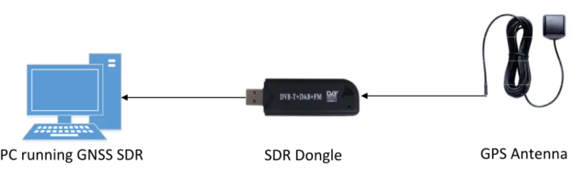
One way to try to address the lack of security of GPS is to use a Software Defined Radio (SDR) [3] capable receiver and modify it in such a way to make it more resilient to attacks. SDR as a concept has been around for some years now, but recently has experi-enced a rapid evolution, taking advantage of the newer capabilities of digital electronics. SDR allows for a software implementation of several components that traditionally were only possible in hardware, like radio filters, modulators/demodulators and detectors. This not only reduces costs and increases ease of use, but can also create better open source alternatives to current offerings. Even a full GPS receiver can be implemented in soft-ware [4] [Figure 1.1]. This would allow for the addition of features to the standard GPS protocol to make it more secure and suitable for use in smart grids.
PC running GNSS SDR SDR Dongle GPS Antenna
Figure 1.1: SDR based GPS receiver.
Another approach to improve security takes advantage of alternative network time synchronization mechanisms. These solutions are advancing at a fast pace and they are currently being studied as a means to synchronize clocks in critical infrastructures, like the electrical grid [5]. Several synchronization systems exist, differing from each other in terms of features, complexity and performance. Today, the most common time syn-chronization algorithms are the Network Time Protocol (NTP) [6] and the Precision Time
Chapter 1. Introduction 3
Protocol (PTP) [7].
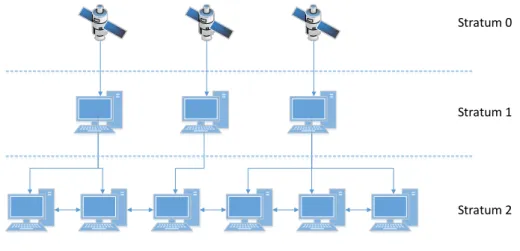
NTP is a network protocol employed to synchronize system clocks among a set of distributed time servers and clients. Since its first appearance in 1985, four versions were released, with the last one being NTPv4 in 2010 [8]. NTPv4 addresses many of NTPv3’s shortcomings, and it can achieve an accuracy of a few milliseconds over the internet, while coping relatively well with variable message delays and dropped packets. It uses a client-server model [see Figure 1.2] with participants organized into different levels called Stratum. Each stratum has a number (starting from 0 at the highest level) representing its distance from the reference clock. The largest stratum level is 15. After this level all nodes are considered desynchronized. Note that even though it seems logical that higher-level clocks have better accuracy, this is not always true because the stratum higher-level can be user-defined and as such it does not always reflect the clock quality.
Stratum 2 Stratum 1 Stratum 0
Figure 1.2: Simple NTP Network.
PTP is currently the most accurate network time synchronization protocol available, with an accuracy that can reach nanosecond precision. It makes use of a hierarchical master-slave architecture to synchronize clocks in a network. Different roles are defined for every clock/node but also to each communication link between them. Special mes-sages that carry very accurate timestamps are exchanged between nodes. In order to reach such high levels of synchronization special care needs to be taken with these timestamps. Even the delays introduced by the packet traversing the Operating System (OS) proto-col stack can have a big impact on the outcome. To address these difficulties, PTP de-fines three modes of operation: software-only, hardware-assisted and hardware only. The software-only is the least precise approach because all timestamps are taken at the applica-tion level of the protocol stack. On the other hand, hardware-assisted and hardware-only
Chapter 1. Introduction 4
modes use special hardware to timestamp the messages as close to the physical layer as possible. The difference between these two modes is related to the place where the PTP implementation actually runs - in software for the hardware-assisted mode and in hard-ware for the hardhard-ware-only mode.
1.1
Requirements
The requirements of a time synchronization protocol suitable for use in smart grids are explained in detail in the standard C37.118-2011 [9]. The standard is split into two parts: the first one presents the measurement (called phasor in this context) estimation require-ments while the second one explains the network communication protocol. The time synchronization requirements are described as the maximum allowed error for PMU’s. Called the Total Vector Error (TVE), it represents the vectorial difference between the estimated and the theoretical phasors in percentages. The requirement imposed by the standard is a maximum of 1% TVE, which equates to approximately 30µs. Even though the standard does not talk about security requirements, the protocol needs to be relatively secure and maintain timing errors below the thresholds. Ideally, this should occur even in extreme situations, such as in the case of an attack or when fault tolerance mechanisms need to do recovery. The fact that each PMU is equipped with a GPS receiver means that it also inherits all the insecurity and problems related to GPS, which in turn makes the implementation of a secure time synchronization algorithm even more challenging.
1.2
Contributions
In this thesis we propose an alternative way of keeping the PMU’s synchronized by resort-ing to a modified version of the PTP protocol. In failure/attack free intervals, the PMU’s continue to employ GPS based clock synchronization. When a problem is detected they switch to our protocol.
The changes to PTP were designed with the following two goals:
• the first aim was to create a protocol that manages to satisfy the time synchroniza-tion requirements of the smart grid, while also being able to cope with the attacks and failures that might happen around the network;
Chapter 1. Introduction 5
• as a second objective, we wanted to minimize the changes to the PTP standard, as this facilitates the updates to the existing implementations and the security evalua-tion.
Most security problems related to PTP are analyzed in some detail in the thesis. There is however a focus on a critical attack vector, namely the GPS receiver, because it functions as the time source for the network devices. As a result of this work, a publication was accepted in the security track of the INFORUM conference.
R. Onica, N. Neves, and A. Casimiro, “Fault-Tolerant Precision Time Protocol for Smart Grids,” in Proceedings of 7oSimp´osio Nacional de Inform´atica INFORUM,
Septem-ber 2015
1.3
Timeline
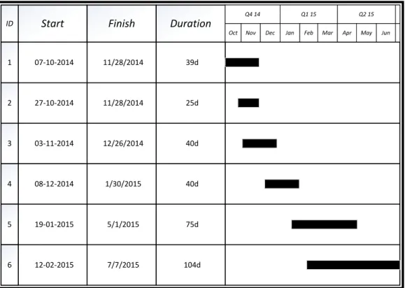
The initial work plan for the thesis is presented as a Gantt chart in [Figure 1.3]. All work tasks are described by their respective ID’s (first column of the chart).
ID Start Finish Duration
Q4 14 Q1 15 Q2 15
Dec Mar Jun
Oct Nov Jan Feb Apr May
1 07‐10‐2014 11/28/2014 39d 2 27‐10‐2014 11/28/2014 25d 3 03‐11‐2014 12/26/2014 40d 4 08‐12‐2014 1/30/2015 40d 5 19‐01‐2015 5/1/2015 75d 6 12‐02‐2015 7/7/2015 104d
Chapter 1. Introduction 6
• Task 1 consists of the study of current GPS and network time synchronization algo-rithms, with a focus being put on their security, or lack thereof. The NTP and PTP protocol were studied and possible solutions to their respective security problems were researched. The environment in which these protocols would need to work, namely the smart grids, was analyzed to better understand the exact requirements;
• Task 2 is the design of an approach that could eliminate (or at least diminish) the impact of possible attacks on the time synchronization. The first approach we came up with was based on using SDR to add security features to the current GPS proto-col;
• Task 3 is the analysis of all available hardware and software solutions to select the ones that would allow for the creation of a framework and workbench to be used for implementing, testing and assessing our proposed approach;
• Task 4 consists of building the framework and workbench with the selected hard-ware and softhard-ware;
• Task 5 is the implementation of the approach and the assessment of its effective-ness. The implementation should be tested against attacks that could happen in the context of a smart grid. The results should be analyzed and compared with the initial requirements;
• Task 6 is to further analyze how the solution performs and to document the results.
The initial approach was based on using SDR along with specific hardware to try to add protection mechanisms to the standard GPS protocol. SDR is responsible for creating the navigation and time solutions from the RAW GPS data that the hardware provides. However, once we reached Task 4, we encountered several compatibility issues with the hardware that lead to unexpected delays in the work plan. When all compatibility issues were resolved, we already had a working prototype of the software that could be tested. At that time, we ran into a second difficulty - the hardware was unable to capture any kind of GPS data.
The problem appeared to be with the SDR dongle or with the antenna - either our SDR dongle was faulty and could not read any kind of GPS data or the antenna was not sufficiently powerful to capture the satellite signal. The dongle managed to collect radio waves in the normal frequency spectrum (like radio stations), which we could decode, but could not receive any kind of signal in the 1575 MHz range that the GPS uses. This
Chapter 1. Introduction 7
led us to think that the problem was with the antenna. To try to find a solution, we experimented with another antenna of a higher quality and additional hardware, namely a bias-T network to power the new antenna. Even so, we had no success at receiving any kind of GPS signal.
This led us to try a different approach. This was the solution that we ended up implementing and testing. It is based on the PTP, and due to time constraints, we decided to employ a software-only version based on the open-source project ptpd2 [10]. Setting up this solution only required a few Linux PC’s and an additional Ethernet card. The first stage was to design the solution to the smallest detail. The next step was to set up the workbench and install the ptpd2 software. After this, the modifications to the standard protocol were implemented and tested.
ID Start Finish Duration
Q4 14 Q1 15 Q2 15
Dec Mar Jun
Oct Nov Jan Feb Apr May
1 10/7/2014 11/28/2014 39d 2 10/27/2014 11/28/2014 25d 3 11/3/2014 12/26/2014 40d 4 12/8/2014 1/30/2015 40d 5 1/19/2015 2/27/2015 30d 24d 4/2/2015 3/2/2015 6 68d 7/7/2015 4/3/2015 7 68d 7/7/2015 4/3/2015 8
Figure 1.4: Gantt chart representing the final thesis work plan.
The new Gantt chart representing the final work plan for the thesis is shown in [Fig-ure 1.4]. Up to Task 4 the plan stayed the same but, the final stages of the work had to be revised:
• Task 5 represents a new research stage in which a different approach was studied to try to adapt the PTP standard in such a way to be used in smart grids;
Chapter 1. Introduction 8
• Task 6 corresponds to the design of a new solution that is suited for use in smart grids and can satisfy all the requirements. This task also includes building the workbench for implementing and testing the protocol;
• Task 7 represents the implementation of the newly designed solution. The imple-mentation is an extension to the PTP standard programmed in the ptpd2 software;
• Task 8 is the testing phase and also contains the documentation of all the work up until this point.
1.4
Thesis outline
In chapter 2, the concept of smart grid is introduced alongside the best time synchro-nization protocols, GPS and PTP. In particular, it explains why the PMU’s deployed in smart grids need to be time synchronized. After explaining the basics about how GPS and PTP work, the chapter discusses several issues that these protocols have, mainly con-cerning their security. For PTP, the major problems in terms of time synchronization are described, namely clock offset and delay asymmetry.
Chapter 3 of the thesis is dedicated to give an in depth explanation of the proposed solution the implementation. After presenting the reasoning behind some of the security related decisions, the attack model explains the capabilities of the adversary. All the changes made to the PTP standard are explained next. The last part of this chapter is dedicated to explaining the details of implementing the attack detection mechanisms using the software of ptpd2.
Chapter 4 presents the tests and experimental results of the work. A detailed explana-tion is given about the testing platform. The implicaexplana-tions and effects of using the existing hardware as the test bed are analyzed and various types of attacks are conducted. The result shows the effectiveness of the proposed solution, making it a suitable candidate for the smart grid time synchronization.
Chapter 2
Context
A thorough study of all the current time synchronization algorithms is essential to lay the foundation for our proposed solution. Understanding the challenges imposed by the smart grid provide motivation and give a clear explanation of what the solution is supposed to do. In this chapter the foundation for this thesis is explained. Some related work on the security of currently available solutions is also discussed.
2.1
The Smart Grid
The smart grid [Figure 2.1] is the next generation of the electrical power system. The smart grid has two primary features: it allows flexible and real-time decision making based on real time data collection and analysis; and it is capable of monitoring its own health and alert operators immediately when problems arise. In some cases, the smart grid may also act automatically, taking corrective actions that will minimize the impact of a failure.
Some of the most important objectives of the smart grid are:
• Accommodate a large variety of energy production technologies including wind, solar and geothermal heat;
• Engage the consumer not only in the consumption cycle but also in the energy production cycle;
• Resilience to attacks, as it needs to mitigate both physical and cyber-attacks;
• Self-healing, since it needs to rapidly detect, analyze and respond to incidents;
Chapter 2. Context 10
Figure 2.1: Smart grid topography [1].
• Empowering the consumer to a certain extent by allowing him to choose when/how energy is bought;
• Accommodate for both the household consumer and industry needs.
In order to implement activities related to the smart grid monitoring, specific devices are being placed at different geographical locations. The PMU is one such device. It is used as a type of advanced measurement device. A PMU can collect electric metrics, such as the voltage and current phasors at precise instants, through a timing reference given by the Global Positioning System (GPS) [see Chapter 2.2]. This can be tough of as a ”snapshot” of the state in which that portion of the smart grid is in. Using multiple PMUs at different points across the smart grid allows for a complete state estimation. This information can then be used to support decisions on the distribution of current load across the network, which in turn gives us the ability to predict and avoid failures like blackouts. Time synchronization among all PMUs is critical because it allows for the creation of a coherent picture of the smart grid. If ”snapshots” are taken at different times, the complete state cannot be correctly estimated.
Current PMUs use GPS receivers for time synchronization. This is a very costly solution because it requires dedicated hardware to be present in each and every PMU. From a security standpoint, it also leaves the PMUs, and in turn the whole smart grid,
Chapter 2. Context 11
vulnerable to even the most basic GPS attacks like blocking or jamming.
2.2
Global Positioning System
GPS was developed in 1973 by the U.S. Department of Defense, as a result of combining previous navigation systems, some of which were classified. It provides specially coded satellite signals that can be processed in a GPS receiver, enabling it to computer its own position, velocity and the time. Four GPS satellite signals are used to compute positions in three dimensions and the time offset between the receiver clock and the satellite clock. The satellites carry very stable atomic clocks that are synchronized with each other and to ground clocks. Any drift from the true time maintained on the ground is corrected on a daily basis.
The current GPS is composed of three major parts or segments:
• Space Segment is composed of all the GPS satellites (also called Space Vehicles). Originally 24 satellites were used, which orbit the earth every 12 hours. They were arranged in such a way that at least six satellites pass over the same location every day. As of December 2012, there are a total of 32 satellites in the GPS constellation. These additional satellites provide redundant information for the receivers, which in turn improve the precision of the GPS receiver calculations;
• Control Segment consists of a system of tracking stations located around the world. This system is composed of:
– a master control station (MCS); – an alternate master control station; – four dedicated ground antennas; – six dedicated monitor stations.
The MCS is located in Colorado at the Schriever Air Force Base. It measures signals from the satellites and then computer precise orbital data (called ephemeris) and the satellite clock correction for each one. It then uploads the ephemeris and clock data to the satellites;
• User Segment consists of all the GPS receivers both civil and military. The naviga-tion in three dimensions is the primary funcnaviga-tion of GPS. It also allows for extremely accurate time dissemination.
Chapter 2. Context 12
Every GPS satellite continually broadcasts a signal that has two important compo-nents:
• A sequence of ones and zeroes called the pseudorandom code that is known by all GPS receivers. The receiver also has the ability of generating the exact same pseudorandom code locally. By comparing the two codes on the time scale (local and received codes) it can calculate the time of arrival of the original code.
• A message that includes the time of transmission of the code epoch (a defined part of the pseudorandom code) and the satellite position at that time.
The GPS satellites transmit data on three different carrier frequencies L1, L2 and L5, the latter only being supported on the newer satellites (at least 5 satellites where launched from 2011, which support the L5 carrier). The data encoding is done using unique code division multiple access (CDMA) [11], so receivers can distinguish between each satellite. This system uses two distinct CDMA encoding types:
• a method based on a code called the course/acquisition (C/A), which is accessible to the general public;
• a method based on a precise (P(Y)) code that is only known and used by the U.S. military and other NATO nations. This code basically encrypts the transmitted data. Devices capable of decrypting this signal are only available to the military and the specifics of the security protocol are kept secret.
The GPS receiver needs to lock on to at least four satellites in order to calculate its position (X, Y, Z) and the time (T). Each message that it receives from the satellite is time stamped (time of transmission). It also gets the time of arrival as previously explained, so it can calculate an estimate of the interval taken for the message to travel from the satellite to itself. Multiplying this value by the speed of light, the GPS receiver, can determine the distance from itself to the satellite.
Distance = ∆T ∗ speedOf Light
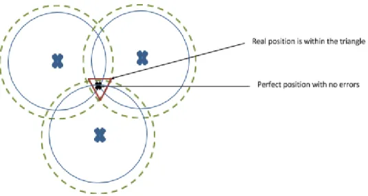
The time interval calculation (∆ T) is not completely precise due to the clocks of the receiver and satellite not being perfectly synchronized (which is actually impossible considering the atomic clocks that the satellites use). This introduces errors in the process of calculating the exact position (trilateration). This process is shown in [Figure 2.2]. The protocol and all messages that are used are explained in more detail in [12] and [13].
Chapter 2. Context 13
The time calculation (ΔT) is not absolute due to the clocks of the receiver and satellite not being perfectly synchronized (which is actually impossible considering the atomic clocks that the satellites use). This introduces errors in the process of calculating the exact position (process called trilateration). This process is shown in Fig. 2.0. The protocol and all message types are explained in more detail in [2] and [3].
Another factor that can contribute to the error is the atmospheric conditions, which can delay the messages. This leads to errors in the position calculation. Fig. 2.0 shows the errors introduced by these factors.
Fig. 2.0 Trilateration process used to calculate current position using GPS
The lack of any kind of protection for the civil band means that many types of attacks exist to try to fool or block the GPS signal. The problem is made even worse by the fact the all the hardware needed for the more advanced types of attacks is readily available to everybody and is relatively cheap considering the circumstances. Some of the known attacks are described next:
- Blocking consists in physically blocking the signal by shielding or removing the antenna of the GPS receiver;
- Jamming overrides the original signal with a more powerful one. This is not that hard to do considering the fact that the parts needed for the construction of a DIY GPS jammer can be readily found. Another important role here is the very weak
Figure 2.2: Trilateration process used to calculate current position using GPS.
2.2.1
GPS Attacks
The lack of any kind of protection for the civil band (the C/A code) means that many types of attacks exist to try to fool or block the GPS signal. The problem is made even worse by the fact that all the hardware needed for the more advanced types of attacks is readily available to everybody and is relatively cheap considering the circumstances.
The way that the GPS signal source is transmitted also turns it into an easy target for attacks. Because of the huge distance that the signal has to travel, its strength is very low when it reaches the earth’s surface. It has often been compared to viewing a normal 20-Watt light bulb from about 19 000 Km away.
The next subsections discuss the most common types of GPS attacks.
GPS Blocking
GPS blocking is the most basic form of attack. This type of attack tries to isolate the receiver from the satellite signal, which in turn leads to a signal loss. It can be performed just by simply covering the GPS antenna of the receiver. It does however require physical access to the GPS receiver in order to be executed which, depending on the adversary, can create some difficulties.
Chapter 2. Context 14
GPS Jamming
GPS jamming attacks [14] [15] are similar to blocking in the sense that they try to make the receiver lose the signal lock. While blocking achieves this by means of isolation, the idea behind a jamming attack is to introduce so much extra radio-frequency noise that the receiver can no longer find the satellite signal out of it. This causes the receiver to be unable to get a lock on the signal.
Considering how weak the satellite signal is, it is not too hard to introduce sufficient radio-frequency noise from a few meters away from the receiver that can completely suppress the original GPS signal. Adding to this, jamming devices are very easy to find on the web and are relatively cheap. Some countries have gone as far as to ban the sale of such devices. It is speculated that the GPS system for an entire city could be prevented from working properly in a flash if the jamming device was sufficiently powerful. To put this into perspective, a device the size of a suitcase could be used from as much as 1000 meters away [16].
GPS Spoofing
GPS spoofing it a more complex type of attack compared to blocking and jamming. It does not block the normal satellite signal but modifies it in such a way to fool the receiver into computing a different erroneous navigation/time solution. The receiver will not be aware of the problem, and therefore it will operate thinking the genuine signal is still being used. This attack can be much harder to detect than jamming.
Some work has already been done in designing spoofing attacks in general [17] [18]. GPS spoofers are also more and more accessible both in terms of cost and of the know-how needed to build them. The manner in which this attack works gives the adversary an extended list of possibilities when it comes to the damage that can be caused. Due to the ”ease of use” and the disastrous results that GPS spoofing can have, some effort is being put into researching, developing and deploying GPS receivers and countermeasures in general, which can cope with these attacks [19] [20].
GPS Software
GPS Software attacks have been recently described [21]. They give the possibility of altering any part of the satellite signal. This can lead to not only the receiver to give an incorrect navigation/time solution, but can even make the receiver crash or downright
Chapter 2. Context 15
become unusable (by exploiting a vulnerability in the executing programs). The fact that manufacturers continue to add features like more connectivity options or even the ability to manage the receiver through the internet, just adds to the problem. GPS as a protocol has limitations from a security standpoint and adding more attack vectors waiting to be exploited does not help to solve the problem.
The attacks demonstrated in [21] show that even high-end GPS receivers can be damaged beyond repair just by modifying a simple parameter in the GPS signal. Again these kinds of attacks are borderline impossible to detect considering the capabilities of the adversary.
2.3
Precision Time Protocol
The precision time protocol appeared as a result of the growing need for high precision time keeping. It was first described in the IEEE 1588-2002 standard, officially entitled “IEEE Standard for a Precision Clock Synchronization Protocol for Network Measure-ment and Control Systems”. A revised version appeared in 2008 as the IEEE 1588-2008 standard [22]. It was designed to fill in the gap left open by the Network Time Protocol (NTP) and GPS. It offers far better accuracy than NTP, but without the need for a dedi-cated GPS receiver at each network node. GPS receivers can be used in combination with a PTP network by acting as a Grandmaster Clock, i.e., the time source for that network.
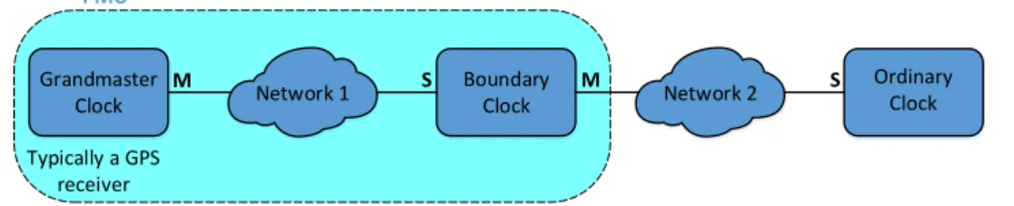
A simple PTP network can be seen in [Figure 2.3]. It is composed of a Grandmaster Clock that is the time source for the network; a Boundary Clock that synchronizes itself to this Grandmaster Clock and then further synchronizes other parts of the network; and lastly an Ordinary Clock. Since a PMU uses a GPS receiver to synchronize its local clock, it can be thought of as being made up of a Grandmaster Clock (GPS receiver) directly connected to a Boundary Clock.
Grandmaster Clock Network 1 Boundary Clock Network 2 Ordinary Clock Typically a GPS receiver M S M S PMU
Figure 2.3: Simple PTP Network (M/S means that the communication port acts as master/slave).
Chapter 2. Context 16
2.3.1
PTP Devices
PTP uses the master-slave architecture for time distribution in which one or more com-munication media are used and one or more clocks. It defines different roles for every clock in the network and various states for every communication port in use:
• Grandmaster Clock : is a clock that synchronizes directly to a GPS receiver. It always runs in PTP master mode, meaning it will distribute its time throughout the network;
• Ordinary Clock : is a normal clock that synchronizes itself to another source. It always runs in the PTP slave mode;
• Boundary Clock : is a clock that both synchronizes itself to a PTP master (acting as a PTP slave) and further distributes the time to another part of the network (acting as a PTP master). Only the PTP slave port of the Boundary Clock has the ability to change the internal clock. The other ports can only read the local clock;
• Transparent Clock : is a special type of clock that modifies all PTP messages that pass through this device, correcting the message timestamps for time spent travers-ing the network equipment. This scheme improves the time distribution accuracy by compensating for the time messages spend in each communication device (e.g., a switch).
2.3.2
Message Exchange
The synchronization is achieved by exchanging PTP messages between the master port of a clock and the slave port of another clock. The messages are divided into event mes-sages and general mesmes-sages. Event mesmes-sages are timestamped with both transmission and reception times. A message is accurately timestamped in two ways: either on-the-fly as it is about to leave the device (called one-step mechanism), or by transmitting another message afterwards containing the timestamp for the first one (called two-step mecha-nism). Only the Sync message and the Pdelay Resp message are affected by the used of the two-step mechanism. For the Sync message, a Follow Up message is transmitted con-taining it’s egress time. For the Pdelay Resp message, a Pdelay Resp Follow Up message is transmitted containing it’s egress time. General messages do not require accurate times-tamps and are used for both synchronization and configuration purposes. All messages are shown in [Table 2.1].
Chapter 2. Context 17
Based on timestamps, the slave calculates the time offset from the master clock and eventually adjusts its local time to be similar to the master. The basic synchronization message exchange is showed in [Figure 2.4] and the logic behind it is explained below:
[email protected]| www.tekroninternational.com
PTP Overview
PTP Operation
IEEE 1588 standardises the Precision Time Protocol (PTP). It defines the descriptors that characterise a clock, the states of a clock and the allowed state transitions. It defines network messages, fields and
semantics, the datasets maintained by each clock and the actions and timing for all IEEE 1588 network and internal events. It also describes a suite of messages used for monitoring the system, specifications for an Ethernet-based implementation and conformance requirements and gives some implementation
suggestions.
Message-Based Synchronisation
PTP is based upon the transfer of network datagrams to determine system properties and to convey time information. A delay measurement principle is used to determine path delay, which is then accounted for in the adjustment of local clocks. At start up, a master/slave hierarchy is created using what is called the Best Master Clock (BMC) algorithm to determine which clock has the best source of time. The BMC algorithm is then run continuously to quickly adjust for changes in network configuration. Synchronisation is achieved using a series of message transactions between master and slaves. There are five message types - Sync, Delay Request, Follow Up, Delay Response and Management - which are used for all aspects of the protocol. A sequence of message transactions takes place to synchronise a pair of clocks as shown in Figure 2.1.
Figure 2.1: Master-Slave offset measurement MS
SM
Figure 2.4: PTP Message Exchange.
1. The master sends a Sync Message to the slave and saves the time t1 at which it was transmitted;
2. The slave receives the Sync Message and notes the time of reception t2;
3. The master conveys to the slave the timestamp t1 by embedding it in a Follow Up Message. Alternatively this timestamp can be embedded into the Sync Message using some kind of hardware processing (this is called the one-step mechanism);
4. The slave sends a Delay Req Message to the master and saves the time t3 at which it was transmitted;
5. The master receives the Delay Req Message and notes the time of reception t4;
6. The master conveys to the slave the timestamp t4 by embedding it in a Delay Resp Message.
Chapter 2. Context 18
Type Message Description
Event
Sync Sent by the master. Contains the egress time of the master node
Delay Req Sent by the slave as a response to the Sync message. Contains the egress time of the slave node
Pdelay Req Used to measure the link delay between two clock ports implementing the peer delay mechanism
Pdelay Resp Used to measure the link delay between two clock ports implementing the peer delay mechanism
General
Announce Contains the clock characteristics like clock quality
Follow Up Delivers the master egress time of the Sync message. Only used in the two-step mechanism
Delay Resp Sent by the master node. It contains ingress time of the Delay Req message
Pdelay Resp Follow Up Used to measure the link delay between two clock ports implementing the peer delay mechanism Management Used for configuration purposes
Signaling Used for configuration purposes
Table 2.1: PTP Message types.
2.3.3
Network Delay and Clock Offset
Considering that the clock offset of the slave relative to the master is ∆ and that the network delay between the master and slave is d(MS) and between the slave and master is d(SM)we have:
t2 = t1 + ∆ + d(M S) (2.1)
t4 = t3 − ∆ + d(SM ) (2.2)
Notice that we have two equations and three unknowns, which prevents us from solving this system of equations. Packets transmitted throughout the network generally suffer different delays in the two directions, and typically there is no way of accurately
Chapter 2. Context 19
measuring the one way delay, i.e., d(MS) or d(SM). However, in order to solve these equations an important assumption needs to be made: the network packet delay is the same in both directions i.e., d(MS)=d(SM)=d. This is an approximation that introduces an error in the calculations, as it is unlikely to hold in a real network. PTP tries to minimize its effect in different ways, such as by taking very accurate timestamps, and by correcting the timestamps when messages go through Transparent Clocks (see Section 2.3.1). Now we can simplify (2.1) and (2.2):
d = t2 − t1 + t4 − t3 2
∆ = t2 − t1 − d
It is now possible to calculate both the one way delay as well as the clock offset ∆. However, because of the aforementioned assumption, the calculated clock offset will have an error that is equal to the difference between the mean delay and the master to slave delay.
There are three main reasons that can lead to asymmetric path delays:
• Operating system latency. This is represented by time the PTP packet spends in the protocol stack. Between the generation of the packet and its transmission on the wire, the packet is manipulated and buffered by the protocol stack. When it reaches the other side, it is delayed by another interrupt. To avoid this problem, PTP packets should be timestamped as close to the physical layer as possible, e.g., at the MAC layer. This approach can reduce the latency introduced by the operating system from milliseconds to nanoseconds.
• Asymmetric link speed. More often than not different links are used for bidirec-tional communication. Two different links almost never have the same exact speed. This can cause some packets to be received sooner than others, which in turn leads to an error in the final calculation of the clock offset. In order to avoid this, the same link has to be used for both directions.
• Network devices. All network devices (e.g., switches and routers) need to do some kind of processing on the packets they receive. No matter what technique is used, buffering and queuing packets takes time, which increases the delay. To try to
Chapter 2. Context 20
minimize the impact that network devices have on network delay, various methods were devised. The simplest method is to give more priority to the PTP packets. The majority of switches and routers nowadays support packet prioritization. This will alleviate the delay introduced by packet processing. In order to completely eliminate this processing delay, a Transparent Clock can be used. The Transparent Clock compensates for the processing time of the packet by changing the included timestamp.
Another method to try to reduce the impact of asymmetric path delays is PTP delay equalization [23] [24]. It appoints a fixed delay to all PTP packets. All network devices would process the PTP packet as to make sure that all of them experience the same known delay.
2.3.4
Best Master Clock Algorithm
In a distributed environment, an algorithm called Best Master Clock algorithm is used to select the best candidate node to serve as the time source. This node will provide the reference time for the network. Selecting the best master takes into account various parameters of each node:
• Clock quality - is the expected deviation from real time. In version 2 of PTP, the clock quality is defined with two data fields, the clockAccuracy and clockClass. The clockClassis used for transitioning a port from one state into another in our imple-mentation. By default the values 13, 255 and 248 are used to designate a master only port, a slave only port or a master/slave port respectively. The master/slave port can run in either of these states. In a network of such clocks only one will be master and the rest will be slaves. The BMC algorithm is used to decide which one should be the master. If all clocks are run in master only mode, after the best one is selected, all others will go into a passive state;
• Priority - is represented by two 8-bit fields known as Priority1 and Priority2;
• Variance - is an estimation of the stability of the clock based on performance ob-servations;
• Identifier - is a universally unique numeric identifier of the clock and is used as a tie breaker if all the other parameters are the same.
Chapter 2. Context 21
Each clock uses an internal data set to save its own parameters and Announce mes-sagesare used to send this information from the current best clock (current master) to all other connected clocks. Whenever a Announce message arrives at a node, a comparison is made between the internal parameters of the receiving clock and the data set included in the Announce message. After this, a decision is made best on the data set comparison. As such the Best Master Clock algorithm can be divided into two phases:
• Data set comparison phase. In this phase the proprieties of two different clocks are compared, as indicated by their respective data sets. The input is represented by data set contained in the received Announce message and the internal data set of the clock that received that Announce message. The output is which one of the two clocks is the most suited to take the role of master.
• State decision phase. After the data set comparison ends, a decision needs to be made as to what is the most recommended state of the internal clock. If the other clock from the comparison is better, the internal clock becomes a slave (or goes into a passive state). Otherwise it becomes the master.
2.3.5
PTP security
Annex K of the Precision Time Protocol standard IEEE 1588-2008 [22] presents several security guidelines that can help the protocol withstand different types of attacks. The guidelines are however completely optional and in an experimental state. They focus on adding two main security mechanisms:
• An integrity protection mechanism, which uses a Message Authentication Code (MAC) to verify that messages have not suffered any unauthorized modification in transit. A message counter is also implemented to help prevent replay attacks;
• An authentication method based on a challenge-response mechanism.
A flag in the PTP message is used to indicate that it is carrying security related infor-mation. Each message following this one is required to also present the same flag or else it is silently discarded without wasting any more resources. In order to ease this process for hardware implementations, the flag field should be the last field in the message. By doing this, an indirect protection against Denial of Service attacks on system resources is created. In [25] a comprehensive threat analysis of the PTP protocol is done and solutions using IPsec and MACsec are explored.
Chapter 3
Fault Tolerant PTP
At the time of this writing, PTP has already been researched as a solution for time syn-chronization in the smart grid environment. However, the main concern of these studies is the clock synchronization accuracy that can be achieved. The security problems of this protocol have yet to be addressed. In this chapter we present a new approach to employ PTP in a smart grid environment. We also discuss the changes to the PTP standard that address the lack of security, when the primary attack vectors are the GPS receivers.
3.1
Overview
Some of the challenges of deploying PTP in a smart grid network are similar to those presented in [26]. Our solution is based on a PTP Boundary Clock [Figure 3.1]. It syn-chronizes directly to a Grandmaster Clock and then distributes this time information to a part of the network.
PTP Slave PTP Master Internal Clock Grandmaster Clock Slave Clock
Figure 3.1: Boundary Clock as originally defined by PTP.
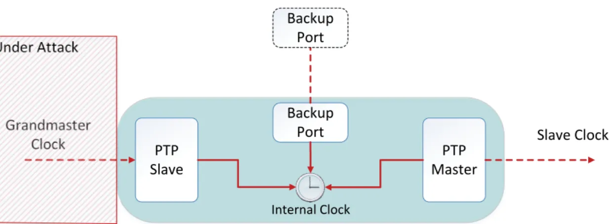
Our modified Boundary Clock [Figure 3.2] acts like a normal Boundary Clock but has an additional port that functions as a backup in the case the Grandmaster Clock fails.
Chapter 3. Fault Tolerant PTP 24 PTP Slave PTP Master Backup Port Internal Clock Backup Port Grandmaster Clock Slave Clock Under Attack
Figure 3.2: Boundary Clock with the proposed modification.
The backup port takes the role of the PTP master once the node identifies misbehavior of the Grandmaster Clock, ensuring that the internal clock remains synchronized with real time. This backup port will be connected with other such ports from various Boundary Clocks around the network. To ensure full time synchronization among all nodes, we need to have several GPS based Grandmaster Clocks and Boundary Clocks spread throughout the network to ensure some geographical distribution. However, if the network delays and jitter allow it, we can use the same GPS receiver for more than one node. Not only does our solution potentially manage to reduce the number of GPS receivers needed but it also supports the detection and mitigation of GPS attacks. This enables the node to always synchronize itself to a time source even if it is not as good (or precise) as the original.
3.2
Attack Model
Our focus is on detecting and mitigating attacks on the GPS receiver (i.e., Grandmaster Clock) that offers time information to the boundary clock as well as on the communi-cation link between them. There is an initial prerequisite that all boundary clocks are synchronized to a correct time source before any attacks occur.
Fault tolerance represents one of the most important concepts in distributed systems design. It enables a computer system to continue operating normally even when one or more of its components fails. This does not imply that the failures do not have any consequence on the system. The computational cost of maintaining the system running
Chapter 3. Fault Tolerant PTP 25
correctly in this case is directly proportional to the number of failures the system is suf-fering. However, in systems with a high degree of fault-tolerance the impact of failures on performance can be eliminated entirely.
We are interested in two main types of failures: crash and arbitrary. Crash failures are self-explanatory. When a system crashes it is unable to continue providing the ser-vice it was initially intended to offer. Arbitrary failures encompass all sort of erroneous behaviors that the component might experience, including delays in producing responses or the transmission of invalid results. Arbitrary failures are also called Byzantine failures referencing the Byzantine Generals Problem [27].
We abstracted the ways in which the Grandmaster Clock can fail into two classes, as perceived by the Boundary Clock:
• Crash failures are observed when the Grandmaster Clock is incapable of sending any type of information to the Boundary Clock. This can happen when the GPS receiver of the Grandmaster Clock is:
– under a Blocking or Jamming attack and loses its satellite signal lock;
– under a Software Attack that crashes the GPS receiver;
• Byzantine failures are assumed when the information received from the Grand-master Clock is incorrect in any way, or when it reaches the Boundary Clock late or in an arbitrary order. This can happen when the GPS receiver of the Grandmaster Clock is:
– under a Spoofing Attack that causes the Grandmaster Clock to give usable but incorrect data;
– under a Software Attack that renders the Grandmaster Clock unable to provide any kind of usable information.
A Byzantine fault is also assumed when the Communication Link interconnecting the Grandmaster Clock to the Boundary Clock is under attack, which in turn causes the time information to be delayed or to reach the Boundary Clock in an incorrect order.
Chapter 3. Fault Tolerant PTP 26
3.3
System Architecture
We define three new port states based on the existing three states of PTP Master, PTP Passive and a PTP Slave. The new port states are called Fault-Tolerant (FT) PTP Master, FT PTP Passive and FT PTP Slave respectively [see Figure 3.3]. As previously mentioned, our modified Boundary Clock distinguishes itself from a normal one by the presence of one extra port that will interconnect various such Boundary Clocks.
• FT PTP Slave has the purpose to detect abnormal activity coming from the Master port it is connected to (in our case this will be the Grandmaster Clock port) and to alert the backup port. It does this by analyzing the time information coming from the Grandmaster Clock, as well as the network delay between them;
• FT PTP Master and FT PTP Passive are port states in which the newly added backup port of the Boundary Clock will run. Their primary purpose is to distribute time information (if the Grandmaster Clock where it synchronizes itself is still con-sidered correct) to other Boundary Clocks.
Grandmaster Clock FT PTP Slave PTP Master FT PTP Master Internal Clock PTP Slave PTP Slave PTP Slave PTP Slave PTP Slave Grandmaster Clock FT PTP Slave PTP Master FT PTP Passive Internal Clock PTP Slave PTP Slave PTP Slave PTP Slave PTP Slave Modified BMC Algorithm FT PTP Passive FT PTP Passive FT PTP Passive FT PTP Passive FT PTP Passive FT PTP Passive GPS Receiver GPS Receiver
Chapter 3. Fault Tolerant PTP 27
The normal PTP Slave port of the Boundary Clock is replaced with a FT PTP Slave. As mentioned before, the backup port of the Boundary Clock will either run in FT PTP Master or FT PTP Passive modes. A modified version of the Best Master Clock algorithm runs between the backup ports with the responsibility of deciding which one is the FT PTP Master. After the best FT PTP Master is selected, all the other ports will go into FT PTP Passive mode. The modified version of the BMC algorithm takes into account another parameter used for disqualifying one such port from the algorithm (see below).
3.4
Solution
In this section we describe how the detection and recovery mechanism works. The state of the Boundary Clock during normal operation and when under attack are displayed in [Figure 3.4] and [Figure 3.5].
FT PTP Slave PTP Master FT PTP Master Internal Clock FT PTP Passive Grandmaster Clock Slave Clock Under Attack
Figure 3.4: Boundary Clock state during normal operation.
When an attack is detected by the FT PTP Slave, it first does a clock jump1 of 2 *
DEFAULT SYNC INTERVAL (1 second in our implementation) ahead, then proceeds to disable itself. The backup port (running in either FT PTP Master or FT PTP Passive) observes the clock jump by reading the clock at each full run of the protocol. Next, it goes into a normal PTP Slave mode. Any out of the ordinary modifications to the internal clock of the Boundary Clock are detected and handled in this way.
The backup port can be in two different states when an attack is discovered: FT PTP Master or FT PTP Passive. As mentioned, in both cases the backup port will go into PTP
Chapter 3. Fault Tolerant PTP 28 Disabled PTP Master PTP Slave Internal Clock FT PTP Master Grandmaster Clock Slave Clock Clock Jump Detect Clock Jump Under Attack
Figure 3.5: Boundary Clock state after an attack was detected.
Slave mode. The difference consists in the fact that if the current state is FT PTP Master, another backup port will need to be elected to go into FT PTP Master state. A modified BMC algorithm is used to perform this change, by comparing data from all the backup ports of the Boundary Clocks.
Notice that we use the local clock of the Boundary Clock as a means to communicate failure detection between the two ports. This is done in order to minimize changes to the standard. In alternative, a low level, high speed communication scheme as presented in [28] could help with the recovery time.
The clock jump performed by the FT PTP Slave will always have to be greater than the DEFAULT SYNC INTERVAL. This is done to make sure that the backup port (now in PTP Slave state) will receive at least one Sync Message from the new time source (in this case the backup port who was elected as the new FT PTP Master from another boundary clock) to compare the origin timestamp from this Sync Message to the current local clock time.
The state change from FT PTP Master to PTP Slave is carried out by modifying the clock class value of this port from 13 (associated with a Master only port) to 255 (Slave only port). Once into PTP Slave mode this port will start synchronizing to the FT PTP Master and the previously set local clock jump will be immediately detected and corrected. In the worst case scenario the recovery time is DEFAULT SYNC INTERVAL + PTP Slave Initialization Time.
Next we describe in more detail how the detection mechanism implemented in the FT PTP Slave works for crash and Byzantine faults.
Chapter 3. Fault Tolerant PTP 29
3.4.1
Crash failure detection
The crash failure detection mechanism is based on the periodic transmission of Announce Messages. The normal behavior of the Grandmaster Clock is to send an Announce Mes-sageevery DEFAULT ANNOUNCE INTERVAL (1 second in our implementation). The FT PTP Slave keeps track of the received announce messages and waits a maximum of announceTimeoutGracePeriod (with a value of 3 seconds) before declaring a packet as lost. We consider the Grandmaster clock failed if two Announce Messages are lost. This translates to a maximum wait time of 6 seconds, which is a lot but serves as a means of testing and verifying the algorithm. Of course, the bounds could be made tighter but with the cost of an increased performance overhead.
3.4.2
Byzantine failure detection
As a first detection layer, all information reaching the Boundary Clock from the Grand-master Clock is filtered to eliminate any bogus data. This will prevent most arbitrary behaviors that cause the transmission of unexpected data. From the previously mentioned attacks, the only one that can do this is the GPS Software attack. This scenario encom-passes most of the attack vectors but two cases need to be treated separately because of their volatile nature:
• Attacks on time. In this type of attack the goal is to try to provide inaccurate time information to the Boundary Clock to desynchronize it. The primary informa-tion used to detect these attacks comes from Sync Messages. An attack can occur in two different ways: either the provided time value jumps forward by a signif-icant amount in one step (clock jump), or the clock is skewed2 gradually step by
step. In order to detect both types, we save the values of the clock offset between the Grandmaster Clock and the Boundary Clock after the clocks are synchronized (Original offset), and the offset calculated in the last execution cycle of the al-gorithm, which is based on the latest received Sync Message. We know that the values will vary very little considering that clocks are already synchronized (pre-requisite). So, if an attacker tries to jump the clock this will be discovered by comparing the original offset with every new calculated offset. The values used to define the maximum allowed offsets are: MAX SECONDS ALLOWED OFFSET, and MAX ALLOWED DRIFT (in ns). The first one is used to detect offset jumps
Chapter 3. Fault Tolerant PTP 30
in the order of seconds. The second one is employed to either find clock jumps by comparing the last known offset with the newly calculated one, or to discover skews by comparing the original offset with the newly calculated one. Special care needs to be given to the MAX ALLOWED DRIFT parameter because it rep-resents the maximum value that the Boundary Clock time is allowed to change at each execution cycle. If an attack increases the clock offset at a rate slower than the MAX ALLOWED DRIFT parameter, time data from other backup ports can be used to detect it. Two maximum offset values were used because time is represented by two fields (seconds and subseconds field) in our implementation. The MAX SECONDS ALLOWED OFFSET and MAX ALLOWED DRIFT param-eters need to be adjusted by measuring and averaging the clock offset and network delays between the Grandmaster Clock and Boundary Clock.
In order to detect clock skews smaller than the MAX ALLOWED DRIFT value we could make use of the communication link between the different backup ports to exchange time information. In this scenario the backup port would need to be in either FT PTP Master or a newly defined state. The objective of this new state would be to measure the clock offset of the internal clock compared to other Boundary Clocks. It could even make use of a secondary internal clock of the Boundary Clock that would be inaccessible by any other means. Only this new state of the backup port would have the ability to modify this secondary clock. This is a Master-Slave scheme similar to the normal PTP where the new state would be responsible for disciplining (modifying the clock in such a way as to synchronize it’s time with another clock) the second clock. This new clock would give us the ability to detect even the smallest of skews (even the drift values) to the first internal clock. The problem is that there is no way of detecting if the Master (in this case, the backup port running in FT PTP Master from another Boundary Clock) is under attack. This means that time attacks consisting of skewing the clock slower than the defined MAX ALLOWED DRIFT would only work on the Boundary Clock whose backup port runs in FT PTP Master. This is still a huge improvement over having no protection at all. Further work can be done to test and evaluate the validity of this approach because it depends highly on the network conditions of communication link between the Boundary Clocks.
• Attacks on the communication link. As previously mentioned the attacker has total control over the communication link between the Grandmaster Clock and the Boundary Clock. This allows him to delay or drop PTP packets. Dropped packets
Chapter 3. Fault Tolerant PTP 31
will make the Boundary Clock think the Grandmaster Clock has crashed, causing the usual recovery actions to be performed.
Delay detection is done in a similar way to the detection of attacks on time but using the network delay as primary information. The delay is calculated by means of the standard delay request-response mechanism [Section 2.3]. Once again we save the first calculated delay value after the clocks are synchronized and the one computed in the last cycle of the algorithm. The main difference consists in the fact that net-work delays can vary more than the clock offset. Therefore, instead of immediately considering the Grandmaster Clock failed, we consider deviations from the normal delay to be outliers. For a delay value to be considered an outlier it has to be greater than MAX OUTLIER DEVIATION (in ns). When a sufficient number of outliers (MAX DELAY OUTLIERS) are detected over a period of time, the Boundary Clock will consider the Grandmaster Clock failed and act accordingly.
3.4.3
Modified Best Master Clock Algorithm
As previously mentioned the Best Master Clock algorithm is used to select the clock that is most suited to distribute time information throughout the network. Announce messages carry information that describes a clock state and quality. As such all clocks use an internal data set to save their own attributes and compare it to the received data set from the Announce message.
Our modification consists in the addition another parameter called isCandidate that is verified at each run of the algorithm. This parameters is used to indicate that a clock is no longer suitable for being a master. This happens when a backup port of a Boundary Clock has detected an attack and goes into slave mode. In addition to the internal data set of the clock, the isCandidate parameters of all the participating clocks also need to be saved internally.
Announce messagesonly matter when they carry information about the current best clock. The isCandidate parameter however has to be verified independently of the state in which a clock is. This happens because even a clock in FT PTP Passive state can fail and needs to be disqualified. Under normal circumstances this would not happen.

![Figure 2.1: Smart grid topography [1].](https://thumb-eu.123doks.com/thumbv2/123dok_br/15493021.1042439/30.892.139.762.112.480/figure-smart-grid-topography.webp)