Dissertação para obtenção do Grau de Mestre em Engenharia Eletrotécnica e de Computadores
J orge Filipe Henriques Correia
Licenciado em Ciências da Engenharia Eletrotécnica e de Computadores
Març o, 2016
Orientador: Pedro Amaral, Prof. Dr, FCT-UNL
J úri:
Presidente: Prof. Doutor Tiago Cardoso Arguente: Prof. Doutor Paulo Pinto Vogal: Prof. Doutor Pedro Amaral
Applic ation development for
S oftware-Defined networks
iii
Application development for Software-Defined networks in state of the art
controllers
Copyright © Jorge Filipe Henriques Correia, Faculdade de Ciências e Tecnologia, Universidade Nova de Lisboa.
v
Aos meus avós
Aos meus pais e irmão
vii
Agradecimentos
Em primeiro lugar gostaria de agradecer esta dissertação ao meu orientador, o professor doutor Pedro Amaral, por sempre me ter apoiado durante a sua realização, mesmo depois de algum desleixo da minha parte. Demonstrou-se Demonstrou-sempre disponível para ajudar, respondendo a todas as minhas questões, por vezes fora de horas, para me permitir terminar esta etapa da minha vida.
Um grande obrigado à Faculdade de Ciências e Tecnologia da Universidade Nova de Lisboa por ter assegurado todos os meios e condições ao longo do meu percurso académico.
Agradeço também à minha família que sempre me apoiou em todas as minhas opções e que fez com que nunca me faltasse nada na vida, fazendo-me feliz, acima de tudo. Aos meus avós, pela ajuda necessária para completar este curso, sendo na calma e confiança transmitida pela minha avó, ou uma palavra sábia transmitida no momento certo pelo meu avô. À minha tia pelas toneladas de conselhos e relatos de experiências vividas que me serviram de lição para os estudos e para a vida. Ao meu irmão, pelas conversas infindáveis até altas horas da madrugada, com tantos desabafos sérios como gargalhadas. E ainda um agradecimento especial aos meus Pais, por todo o seu esforço e dedicação, por quererem sempre o melhor para mim, por estarem sempre presentes quando mais preciso. É graças a eles que consigo concluir mais uma etapa na minha vida e é a eles que dedico todo o meu trabalho. Nunca uma página será grande o suficiente para transmitir o quão agradecido estou, mas fica um profundo Obrigado por tudo o que têm feito por mim.
Finalmente, mas não menos importante, à minha namorada. Minha fiel companheira que nos últimos mais de quatro anos me surpreendeu todos os dias dando-me a conhecer uma das melhores pessoas que já conheci. O seu apoio incondicional e o seu altruísmo, que tiveram o ponto alto na ajuda prestada na elaboração desta dissertação, nunca serão devidamente pagos, mas todos os dias o tentarei fazer de qualquer maneira que me seja possível.
ix
Abstract
In the last few years, the importance of the internet in our lives increased considerably.
Networks have become a big part of our lives and there will be a setup almost everywhere we go: in our homes, in the workplace, in stores, in universities, in the subway. Each and every one of these places has a network, a router, Wi-Fi, etc. Due to its high importance, service providers must guarantee a fully operational network, 24 hours a day, leaving no room for mistakes.
However, that creates a problem: how can developers test new protocols? In no way is a service provider willing to risk ruining its network because a developer tested a non-working protocol.
x
functions that work in a distributed manner and considering they are made by a limited number of manufacturers, these networks present several limitations. Besides its complexity and configuration, it must be taken into account that every network should be prepared to deal with potential failures that might occur, as well as any security-related problems. A network - regardless of its level of use - must allow its users to use it as safely as possible.
Networks today have poor flexibility and their development, growth and innovation are far from simple. Thus, the provision of more diversified services to satisfy the users presents a challenge to service providers, since the system and the administration functions are separated.
The answer to these problems lies within the Software-Defined Networks (SDN), given that they seem to be very promising as far as innovation is concerned, allowing the development of new strategies and management control networks.
These networks use programmable switches and routers that can process packets of data for several isolated experimental networks simultaneously, through virtualization. These networks run in the Control Plane, in servers operating separately from the network devices. This gives the network administrator a greater control over the network, as it allows to manage different resources by directing them to different traffic flows.
A SDN using OpenFlow is capable of supporting a high-response network to each and every controller failures that might occur, without slowing the network's response, as it offers great flexibility and helps with fighting the limitations of any existing network.
xi
pinpoint the advantages and disadvantages of SDN with an OpenFlow architecture.
xiii
Resumo
Nos últimos anos, a importância da internet nas nossas vidas aumentou consideravelmente.
As redes tornaram-se uma grande parte das nossas vidas, e nos sítios que frequentamos no nosso quotidiano: nas nossas casas, no trabalho, nas lojas, nas universidades, no metro. Aqui, é quase sempre possível encontrar uma rede, um router, uma rede Wi-Fi, etc. Devido à sua elevada importância, os prestadores de serviços devem garantir uma rede totalmente operacional, 24 horas por dia, sem haver margem para erros.
No entanto, isso cria um problema: Como é que se podem testar novos protocolos? Os prestadores de serviços não estão dispostos a arriscar arruinar a sua rede porque um programador testou um protocolo que pode comprometer a rede.
xiv
grandes quantidades tráfego e com diferentes caraterísticas. O prestador de serviço necessita de processar uma grande quantidade de dados simultaneamente, enquanto encaminha tráfego. Como estas redes contêm funções internas de controlo que funcionam de forma distribuída e considerando que são desenvolvidas por um número limitado de fabricantes, estas redes apresentam várias limitações. Além da sua complexidade e configuração, estas redes também têm de estar preparadas para lidar com potenciais falhas que possam ocorrer, assim como com problemas de segurança. Uma rede – independentemente do nível de uso- deve ser o mais segura possível.
As redes atuais têm pouca flexibilidade e o seu desenvolvimento, crescimento e inovação são tarefas complexas. Portanto, a prestação de serviços mais diversificada para satisfazer os utilizadores representa um desafio para os prestadores de serviços.
A resposta para estes problemas está no paradigma das redes definidas por software (SDN), dado que as SDNs são muito promissoras, quanto à inovação e à possibilidade de automação e mais independência do hardware.
Estas redes utilizam switches programáveis que podem processar pacotes de dados de acordo com as regras instaladas por um plano de controlo separado, gerido em software. Isto dá ao administrador de rede um maior controlo sobre a rede, já que permite gerir os recursos, direcionando-os para diferentes fluxos de tráfego.
Uma rede definida por software, que use o protocolo OpenFlow, oferece uma resposta rápida para cada falha que possa ocorrer no controlador, sem atrasar o funcionamento da rede, Oferece uma grande flexibilidade e ajuda na luta contra as limitações das redes tradicionais.
xv
saber mais sobre este tópico. Um dos focos é mostrar as vantagens e desvantagens das SDN com o protocolo OpenFlow.
xvii
Contents
1. Introduction ... 1
Motivation ... 1
Objectives and contributions ... 5
Thesis Layout ... 5
2. State of the Art ... 7
Typical Network Architecture ... 7
The Road to Software-Defined Networks ... 8
Network Virtualization ... 10
Common problems of Traditional Networks ... 12
Software-Defined Networks ... 13
SDN Architecture ... 15
Security issues of SDN ... 18
OpenFlow ... 21
2.8.1. OpenFlow Protocol ... 21
2.8.2. OpenFlow characteristics ... 22
2.8.3. OpenFlow Switch ... 23
Building SDNs for simulations using virtual software switches 26 2.9.1. Mininet ... 26
2.9.2. Floodlight Controller ... 27
OpenFlow Concepts in Floodlight Controller ... 31
xviii
2.10.2. Matches ... 33
2.10.3. Actions ... 33
2.10.4. Instructions ... 33
2.10.5. FlowMods ... 34
2.10.6. Groups ... 34
2.10.7. Packet-Ins ... 35
2.10.8. Packet-Outs ... 35
2.10.9. Meters ... 36
2.10.10. Collect switch statistics ... 36
Conclusion ... 37
3. Developing Applications for Software-Defined Networks ... 39
Example 1 ... 40
3.1.1. Developing the floodlight module ... 42
3.1.2. Emulating the network on Mininet ... 43
3.1.3. Implementing the behaviour step by step ... 44
3.1.4. Connect Mininet topology to Floodlight controller ... 49
Example 2 ... 54
3.2.1. Application Development ... 56
3.2.2. Connect Mininet topology to Floodlight controller ... 60
4. Conclusion ... 63
Conclusions ... 63
Future work ... 64
xix
Figures
Figure 1.1: View of traditional networking ... 2
Figure 1.2: Architecture and structure of a SDN ... 4
Figure 2.1: Virtual Network integration in physical infrastructure ... 11
Figure 2.2: SDN architecture... 15
Figure 2.3: Set of flow entries ... 254
Figure 2.4: Architecture OpenFlow ... 245
Figure 2.5: Set modules in Floodlight controller ... 29
Figure 3.1: Network Topology ... 40
Figure 3.2: Topology used in Example 1 ... 43
Figure 3.3: Flow configuration of switch S1 ... 49
Figure 3.13: Topology used in Example 1 ... 56
Figure 3.14: Flows in Switch S1 ... 61
xxi
Tables
1
1.
Introduction
Motivation
Today’s computer networks and infrastructures constitute an important service to society, by serving as infrastructure for several other services. However, the inflexibility of the traditional networks’ architecture is becoming a problem.
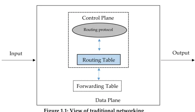
Network operations can be divided into two levels designated by data plane and control plane [1], as shown in Figure 1.1. In traditional networks these two levels run within each switch.
The data plane is responsible for forwarding packets from one device to another. The control plane consists in the protocols used to produce the decisions on how to forward the packets. These decisions are usually enforced by the forwarding tables of the switches, routers and all data plane devices.
There are also software services which are used to remotely monitor and configure the control functionality.
2 Router
Data Plane
Figure 1.1: View of traditional networking
Traditional networks are composed by several kinds of equipment, from routers and switches to middleboxes, such as network address translators, firewalls, server load balancers, and intrusion-detection systems [1].
In traditional networks the architecture itself and its configuration are responsible for a large percentage of errors. The device’s software differs from manufacturer to manufacturer, and sometimes even from product to product, within the same manufacturer. In addition, network administrators need to configure every device individually and are prone to committing various errors. In fact, configuration errors still account for a large percentage of data center failures and are the number one security threat. However paramount, reconfiguration and response mechanisms are still virtually non-existent in current IP networks [1].
Moreover, with the addition of thousands of network devices that must be individually configured and managed, networks became vastly more complex.
Control Plane
Routing protocol
Routing Table
Forwarding Table
3
When a network device is added, the control plane on every existing network’s elements needs to be updated, which leads to an ossification of the network. The deployment of new services requires individual configuration of every network equipment, which is very time consuming and sometimes entails the installation of new devices. This is blocking innovation and has been hindering networks’ management. So, the network designers have to implement sophisticated policies and tasks, by using a limited and restrictive set of low-level device configuration commands, in order to meet systems requirements and guarantee their good performance.
Software-Defined Networks offer a new paradigm that tries to overcome the mentioned obstacles. SDNs have four basic design characteristics: [1]
1. The control and data plane are decoupled; 2. Forwarding decisions are flow-based;
3. Control logic is moved to an external entity, the SDN controller or Network Operating System (NOS);
4
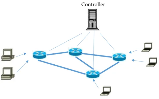
The following image presents the structure of a Software-defined Network:
Figure 1.2: Architecture and structure of a SDN
These aspects are key factors to simplifying network management and enabling network evolution and innovation [1]. In spite of the benefits of this new paradigm, the security and dependability of the SDN itself are still an open issue [2]. However, SDNs are already a reality with several application examples. In data center networks they are already replacing traditional networks, and several examples of their use in service provider networks and campus networks are also already in production. Standards like OpenFlow (a southbound API between the control plane and the data plane) are already implemented in modern equipment, and several equipment vendors and network operators are committed to the development of controllers and Network Operating Systems ecosystems.
5
Objectives and contributions
The main objective of this thesis is to study the state of the art in the development of software applications for software defined networks. In this process we will:
Present the Software-Defined Networks paradigm and identify its characteristics;
Present the OpenFlow protocol and its characteristics;
Explain and document how to program SDN applications that use OpenFlow.
The main contribution will be the presentation of a systematized view of how to implement applications for SDNs in a current state of the art controller.
Thesis Layout
7
2.
State of the Art
Typical Network Architecture
Network devices are responsible for receiving the packets, checking the packets headers, and deciding where to route them. There are network devices operating in Layers 1, 2 and 3. In Layer 1 we have a HUB, which only retransmits what it receives, without checking anything, thus working as a signal repeater. In Layer 2 there are Switches, which interconnect computers from the same network. Finally, in Layer 3, we have a Router which interconnects computers and other devices from different networks.
On these networks, the Switch has two levels: the Control Plane, that checks the packets’ headers and decides where to route them; and Data Plane, that forwards traffic to the next hop, according to the Control Plane’s decision. So, when a packet arrives at a Switch, the Control Plane examines it, decides where to send it and communicates the decision to the Data Plane, which then proceeds to sending the packet to where it is supposed to go.
This communication between the Control and Data Planes happens inside the switch, which has vendors’ closed software and hardware. This limits the ability to engineer and manage traffic across equipment from several vendors. On top of that, the algorithms of the Control Plane have to be configured
8
before the switch is installed, and if the network administrator wants to add another rule he has to access the switch and change it manually.
The architecture of current networks is based essentially on the use of layered networks which divides the information in different units of varying sizes called packages. These packages are generally lower than the size of the original message and are sent by alternative routes [3]. This characteristic makes for greater effectiveness in the communication network, because if there is a network failure the data flow is not interrupted [4].
The current architecture of networks meets the following specifications [4]:
Connectivity; Generality; Heterogeneity; Robustness; Accessibility
The Road to Software-Defined Networks
One of the first examples of control centralization in a network came in the 1990s, when AT&T introduced Network Control Point (NCP) [5], with the separation of the voice and the signaling channels in the telephone network.
9
Database), and shorter holding time due to the fact that the NPC could know the status of a line, so it would route the call through the quickest line available. This type of control was called Central Control and is still used today by AT&T.
Computer Networks nowadays involve many kinds of components like Switches, Routers, Firewalls, Network Address Translators, Server Load Balancers, among others. That conjunction of equipment makes the networks complex and difficult to manage.
The architecture of a network Switch has two levels: data plane, which deals with packet switching; and control plane, which does the routing decisions for the packets. The decision process of switching or routing and the actual data plane are, typically, on the same device. This creates a tight relation between the control and data planes, which makes tasks like debugging configuration problems very difficult.
There are several kinds of Switches in different layers of the OSI model. In layer 1 the Switch is used as signal repeater and regenerator, in layer 2 it interconnects devices that belong to the same network, and in layer 3 it interconnects devices from different networks.
The networks’ configuration process consists on having the network’s administrator configure each device individually, using different interfaces that diverge from vendor to vendor, and sometimes even from device to device, both from the same vendor.
10
Therefore, this mode of operation has blocked innovation, caused poor performance due to redundant operations at different protocol layers, increased complexity, created major scaling problems, and raised the costs of running a network.
The first attempt to solve some of these issues was Active Networks, of which there were two kinds: Integrated and Discrete. In the integrated approach, each message contains a code which will be evaluated by every programmable middle box (or active node) and then ran in an execution environment of those middle boxes. On the discrete kind, the code is installed in the active nodes, and the packets are dispatched to the appropriate code block based on the values on the packet headers.
These networks were a great step towards Software-Defined Networks, but came too soon. At the time, there was no application for these Networks since data centers and cloud computing did not exist. Other major issues that prevented the Active Networks’ success was the idea of having code passing through the network, which raised many security concerns and the need of hardware and firmware upgrades due to lack of operability with the existing networks.
Network Virtualization
11
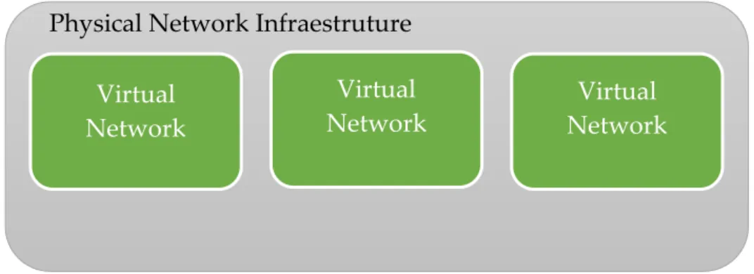
Figure 2.1: Virtual Network integration in physical infrastructure
For the user, there is no difference in using a logical partition or a physical network, but for network managers it is a big improvement in terms of managing networks. There are several resources available to a network such as switches, routers and virtual machines. These resources can be used by several logical partitions at the same time, without interfering with each other, and can be reallocated in real time in order to obtain better efficiency. If one instance of the network has a lot of resources allocated, but is not using all of them, they can be reallocated to a struggling partition with a lot of traffic at that moment. So with virtualization, the use of a physical network infrastructure is maximized, because instead of one network, it is possible to have multiple other network instances, so the costs are decreased as well, because the network resources are shared by several networks as needed at any given time.
Virtual Network
Physical Network Infraestruture
Virtual Network Virtual
12
Common problems of Traditional Networks
The growth of networks, as well as their importance, is undeniable. With this growth the amount of hardware needed is larger, therefore some scalability problems occur. Networks are configured using commands or network management systems [27], so it is a very time consuming work to set up a new network, or to change a certain parameter in every hardware of the network.
The rise of the cloud, mobile computing, data centers and other trends like Internet of Things demands good performance from the networks, and because they require timely adjustments to change their configurations, they can be considered essentially static and inefficient at deploying dynamic services such as ensuring resources to applications when they need it the most. This means the adaptation of these networks to new services may take years, since they need feature upgrades, architecture adjustments or introduction of new devices to meet new service requirements. For example, the traditional Layer 2 VLAN mechanism of a cloud data center with virtual machines and virtual networks is required to run new protocols on switches to meet scalability requirements; however, the physical devices involved cannot adapt to these requirements quickly enough.
Software-defined networks are a viable possibility to solve the problems presented above and will be described ahead. These networks are able to provide better visibility into the network, making troubleshooting the network easier. Anomalies from the network can also trigger actions to identify where the problem is and possibly solve the issue.
13
Software-Defined Networks
Traditionally, networking relied and evolved over a non-transparent distributed model for the deployment of protocols and configuration of devices that resulted in complex protocols and intrinsically difficult configuration of network devices [5].
Software-Defined Networks present a new way of thinking in networking, shifting the complexity of protocols and management functions from the network devices to a general purpose logically centralized service. The motivation behind this decoupling is to simplify the operation of the network for users.
Software-Defined Networks (SDN) are based on virtualization and allow software to run separately from the hardware. The routing decisions (Control Plane) are separated from packet switching (Data Plane), leaving the decisions regarding where traffic is sent to be handled by a centralized Control Plane, which knows the state of the entire Network at any given time. This separation of Control and Data Planes gives the Switch more process capability and can virtualize the network environment, offering at the same time a much more programmable network due to the fact that only one element has to be configured: the centralized controller. This also allows network developers to develop new protocols that can control the Data Plane, and to test it without configuring every switch of a given network.
Understanding the biggest contributions in the SDN research field allows for a better picture of its composition, benefits, and drawbacks, thus historical changes in networks that have molded the current SDN architecture [5].
14
As previously seen, the history of SDN takes us back to when the incredible success of the Internet exacerbated the challenges of management and evolution of the network infrastructure, in which the focus was on innovation in the networking community. However, these innovations were in some cases catalyzed by progress in other areas, including distributed systems, operating systems, and programming languages. Efforts to create a programmable network infrastructure also clearly refer to the long list of discussion about the programmable packet processing at high speeds. Based on the above, the history of SDN can be divided into three main stages: (1) The first stage concerns the ideas of active networks (mid-2000) in which functions that were programmable were introduced, and originated more creativity and evolution; (2) The second step concerns the separation of data and control plane (mid 2001). Finally, (3) the third step relates to the emergence of OpenFlow, considered an open interface to make the separation of control plane and data plane [6].
In addition to that, an important aspect, as seen previously, is that the Software-Defined networks constitute a much larger universe than the one defined by the OpenFlow.
OpenFlow provides a simple solution for creating multiple virtual networks on a physical infrastructure, where each network consists of switches and routers. But the paradigm of Software-Defined Networks makes it possible to develop new network applications, something that was thought in the past, in traditional networks [13].
15
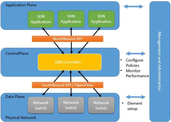
SDN Architecture
Like in a traditional network, a SDN is composed of network devices. The main difference between them, is that in SDN the network devices are simple processing elements without embedded control or software to take autonomous decisions. This means the network intelligence is removed from the data plane devices to a centralized logic [1].
To ensure compatibility of configuration and interoperability between different control and data plane devices, these new networks are built on open and standard interfaces such as OpenFlow [1]. In the following figure is displayed a view of an SDN architecture.
Figure 2.2: SDN architecture
16
network virtualization, network monitoring, intrusion detection (IDS) and flow balancing that communicate with the SDN Controller. This layer is completely isolated from the physical network.
Following, comes the Control Plane to support data management applications and the set-up containing the “brain”, the SDN controller, making the routing decisions. It provides abstractions, essential services and common application programming interfaces for developers [2]. Between Application Plane and Control Plane, are the northbound application program interfaces (API), which provide a channel that allows the SDN Controller to send instructions to the applications running over the network, and help network administrators to shape traffic and deploy services.
The last layer is Data Plane, the physical network containing the switches and other network elements, used to forward packets [8], respecting the SDN controller rules and policies. Between the SDN controller and the physical network are the southbound application program interfaces (API) that provide a channel by which instructions are sent to the devices to program them. These APIs use a routing protocol and enable the SDN Controller to make instant changes to face with real-time demands.
In this architecture there are two main elements, routing/forwarding devices such as switches and the controller. An OpenFlow forwarding enabled device is based on a set of flow tables. Each entry of a flow table has three parts, one matching rule, actions to be performed in matching packets and counters to keep the corresponding packet statistics. When a packet arrives, the lookup process begins in the first table and ends with a match in one of the frames (or a rule is not found) [1].
17
a much more programmable network due to the fact that it is only necessary to configure one element: the centralized controller. This also allows network developers to test new protocols without configuring every switch of a network. With this information and based on an appropriate communication protocol, in this case OpenFlow, the controller sets the specific flow in each element involved, enabling the routing package. However, it is important to emphasize that the packets in the same flow are pre-configured and therefore will not need to perform a new query to the controller.
The SDN and its architecture objectives are facilitating network management and ease the burden of solving network problems through a logically centralized control offered by a network operating system (NOS).
At an architecture level, one of the most important aspects is having the controller as a central controller for the whole network, so there is only a single entity that ultimately manages all network devices. However, if this entity fails or if a malicious person takes control, there can be serious problems because the one who controls the SDN controller, can control the entire network [2].
Another important aspect that needs to be mentioned relates to the controller. In this architecture, as there is a centralized element, all information is concentrated in one place. Each reading operation, after a writing operation, returns an updated value [1].
With distributed elements, it is important to define strategies to ensure the consistency of data updates.
18
In spite of its impact on the performance of the system, strong consistency offers a simpler interface for application users when compared with low consistency [9].
Another important aspect to be mentioned is the fault tolerance. When a node fails, the other node must assure the operation of the failed node. Until now, despite some controllers having trouble of collision, there are no arbitrary failures, i.e. any node with an abnormal behavior will not be replaced by a more appropriate behavior [1].
However, it is important to take into account, to assure the safety of SDN, the following architecture aspects: availability, performance, integrity and confidentiality [10].
OpenFlow is considered the first standard in SDN, it was the original southbound API and remains as one of the most common protocols.
Security issues of SDN
The countless promises of a simplified control and a real-time programming offered by SDN constitute incentives for operators to keep the evolution at an accelerated pace. However, these questions raise barriers to safety, and the aim is that this will serve as a complement to secure architecture so that networks are protected against attacks by malicious users [10].
Looking at SDN characteristics, it is possible to verify that the main security problems lie on SDN’s greatest benefit, i.e. the programmability and logical network centralization.
19
First the non-SDN-specific threats. Compared with traditional networks, the separation of the control and data planes enables multi-tenancy and programmability, and introduces centralized management into the network architecture. From a security perspective, the ability to share and dynamically operate the same physical network is one of the key security-related differences between SDN and traditional architectures. As such, SDN security issues relate to the new control plane model, and more specifically to securing inter-component communication, and controlling the scope of applications and tenants through specific APIs and access policies [10].
While it may sound like there are a number of obstacles to overcome, the programmability and centralized management brought by SDN enables a much greater level of autonomy to mitigate any security breaches [10].
Another problem is the falsification of a flow. The traffic flows can be forged or faked by a faulty (non-malicious) device or by a malicious user that can be used to attack switches and controllers.
20
For this threat, the solution is to use software attestation mechanisms or mechanisms to monitor and detect abnormal behavior of network devices using switches. Recovery mechanisms are very important in a network, i.e., when there is a network problem it is important, of course, to understand their cause and to recover by resetting. For that purpose, reliable information is needed from all components and domains of the network [2, 10]. Finally, related to non-specific threats it is important to refer that the created logs should be stored in a remote and secure environment [2].
Concerning SDN specific threats, it is important to refer to the form of communication between the three planes, namely the existing communication between both controller and applications. Attacks performed here can be used for data theft [2].
21
OpenFlow
2.8.1.
OpenFlow Protocol
The OpenFlow is a standard protocol which is managed by the Open Network Foundation (ONF), a user-driven organization who wants to promote SDN, leading to a worldwide adoption of this kind of Networking. ONF is responsible for managing and publishing OpenFlow specifications.
In a conventional network model, the decisions regarding where an incoming packet should be sent and fast packet forwarding occur in the Switch. An OpenFlow Switch allows the intelligence to be made on a centralized separate controller. The OpenFlow Switch and Controller communicate via the OpenFlow protocol, which defines messages, such as packet-received, send-packet-out, modify-forwarding-table, and get-stats. This means the policies and rules can be changed as network and application requirements change, and can be done immediately, being automatically propagated throughout the network. This makes network management much easier.
22 Other benefits of OpenFlow are:
More flexibility and control of software and simulation. More speed and scalability of vendor hardware.
Vendors do not need to expose their closed implementation.
OpenFlow had several versions. A presentation of the evolution of the protocol will be presented.
2.8.2.
OpenFlow characteristics
To better understand how OpenFlow [26] protocol works, several concepts should be described before:
Packet - an Ethernet frame, including header and payload;
Flow Entry - An element in the flow table used to match and process
packets. It has match fields and a list of instructions with one or more actions;
Flow Tables - Contains at least one flow entry. Since OpenFlow version
1.1 a switch can have more than one flow table enabling the pipeline search, which will try to match to the first flow table, then the second, and so on. A flow table can have a flow entry with an action instructing for the packet to be immediately sent. In this case, the switch will not try to match the packet with the remaining flow tables;
Match or Match Field - A field to which a packet is compared including
packet headers, the ingress port, and the metadata value. It is possible to match every packets by wildcarding this field. Usually when a packet is matched, an action is assigned to that packet.
Action - The element that can forward the packet to an outport of the
23
field, when the packet leaves this field will have the value from the last action. A list of actions can be found at [26];
Action Set - a set of actions associated with the packet that are
accumulated while the packet is processed by each table and that are executed when the instruction set instructs the packet to exit the processing pipeline;
Instruction - instructions describe the OpenFlow processing necessary
when a packet matches the flow entry. An instruction either directs the packet to another flow table, or contains a set of actions to add to the action set, or contains a list of actions to apply immediately to the packet;
Action Bucket – used in groups. It is a set of actions and associated
parameters that will be applied when a packet is sent to a group;
Group - a list of action buckets that will be applied to the packets. It has
the means to choose which buckets will be applied to each packet
2.8.3.
OpenFlow Switch
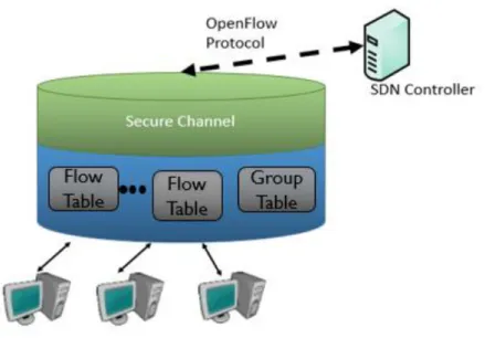
At first, in OpenFlow 1.0, an OpenFlow Switch contained two main components:
A Secure Channel necessary to connect to the SDN controller through the OpenFlow protocol. With this protocol, the controller can add, update, and delete flow entries.
A Flow Table that contains several flow entries, and does packet lookups and forwarding.
24
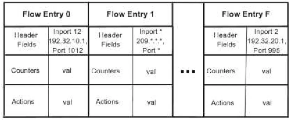
A flow table consists of flow entries, and each flow entry has the components shown in Figure 2.3.
There is a search made to all packets arriving at a switch, to see if there is a match at the flow table. The flow table contains a set of flow entries, and each of them has three components: Header Fields (to match packet headers), counters
which are updated when a packet is matched with this flow entry, and a set of
actions to apply to matching packets (ex.: forward the packet to a specified port, or forward the same packet to more than one port).
Figure 2.3: Set of flow entries
The SDN Controller determines how to handle packets that did not find any matching flow entry. These packets are sent by the switch through the secure channel, and then the controller adds a flow entry on the switch for that kind of packets, deletes or updates a flow entry or drop the packet.
25
Figure 2.4: Architecture OpenFlow
The process of matching a packet to a flow entry starts at the first flow table, proceeding to the next tables. When a match is made, an action on the packet may be performed. If a packet does not match with any flow entries, depending on the configuration, the packet could be sent to the controller over OpenFlow channel, or dropped.
The group table contains group entries, and each group entry has a list of Action Buckets (which are a list of actions), therefore, a group entry has a list of list of actions.
26
Message Type Sent by Description
Request
features
Controller Asks a switch for its configuration (i.e. port information)
Request stats Controller Asks a switch port or flow statistics (i.e. byte
and packet counters)
Packet Out Controller Send a specific packet through a specific out
port
Flow
modification
Controller Insert, update or delete a flow entry in the switch’s flow table
Features reply Switch Switch description of its features (i.e. ports) Stats reply Switch Report of port or flow statistics from the
switch
Packet_IN Switch Sent when a packet arrives and has no
matching rule, or has a rule whose action directs the packet to the controller
Flow removed Switch Notification that a flow entry was removed
due to a request from the controller or due to timer expiration
Table 2.1: Summary of the key OpenFlow messages
Building SDNs for simulations using virtual software
switches
2.9.1.
Mininet
Mininet [17] can create a network of virtual switches, controllers, links and hosts. Hosts run Linux and switches support OpenFlow.
27
development. It is possible to implement simple or complex topologies and find the best performance possible for a network, with a given hardware. It has a Command- line Interface that is topology-aware and OpenFlow-aware which is perfect for debugging.
Mininet’s networks run code used on real networks that is why it can be moved to a physical network with minimal changes in order to evaluate the real performance of the implementation, which may be similar to networks’ performance on Mininet.
Instead of virtualizing computing resources Mininet uses process-based virtualization to run many hosts and switches on a single OS kernel. So it is faster, offers the possibility of having more hosts and switches, provides more bandwidth and is easily installed than others emulators that use full system virtualization. Compared to hardware testbeds, Mininet does not need any money to test a network and it is quickly reconfigurable and restorable.
Mininet has some limitations. It has resource limits, the server resources have to be shared and balanced between the virtual hosts and switches. Using only Linux kernel for all hosts means it is impossible to run software that depends on other system kernels.
2.9.2.
Floodlight Controller
As explained before, every Software-Defined Network needs a controller. A controller is responsible for managing flows on the switches’ flow tables, and can do it remotely and on real time. SDN controllers are the “brains” of the networks because they can tell any switch / router where to send packets.
28
Floodlight is an open-source Controller. It is easy to set up, having minimal dependencies and is user friendly and developer friendly because it uses a module system (written in Java) that makes it easy to extend, adapt software and develop applications. It has Representational State Transfer Application Program Interfaces (REST APIs), that can be written in any language and exchange information with an external entity at runtime. This controller can work with OpenFlow and non-OpenFlow networks.
The Controller performs the typical network operations, monitoring the network and updating flow tables in the switches while having applications, built as Java modules or over the Floodlight REST API that can be written in any language, realizing other features according the user needs over the network.
29
Figure 2.5: Set modules in Floodlight controller
The Module Applications implemented in floodlight are represented in Figure 2.5.
Virtual Network Filter (VNF). A MAC-based network isolation
application which is not enabled by default. Exposes a variety of REST API that allow add, remove and inquire virtual networks.
Firewall. Application that can apply Access Control List (ACL) rules to
allow or deny traffic based on a specified match. Exposes a variety of REST API that allow to enable or disable the firewall and add, remove or list rules.
Forwarding. A default reactive packet forwarding application which will
30
switches Forwarding has to take this into account. The algorithm will find all OpenFlow islands that have device attachment points for both the source and destination devices. FlowMods will then be installed along the shortest path for the flow. If a PacketIn is received on an island and there is no attachment point for the device on that island the packet will be flooded.
Hub. An application that flood any incoming packet to all active ports,
except the port from which the packet arrived.
Static Flow Entry Pusher. An application that can install a specific flow
entry in a specific switch. Exposes a variety of REST API that allow to add, remove and inquire flow entries.
Learning Switch. A L2 learning switch. Exposes a REST API that allow to
list the current switch table.
Port Down reconciliation. An application to reconcile flows in case a
port or link goes down.
Some examples of REST applications that use floodlight REST APIs are:
Circuit Pusher, that can create a permanent flow entry on all switches in
route between two devices based on IP addresses with a given priority.
OpenStack, that allows Floodlight to run as the network backend for
31
OpenFlow Concepts in Floodlight Controller
The controller will be able to interact with network switches writing messages to the switch and processing the messages from the switch.
The OpenFlowJ-Loxigen is a single, common, version-agnostic API that support OpenFlow versions from 1.0 to 1.4. It provides builders for several OpenFlow Concepts. Before explaining how to develop a network, it makes sense to explain these concepts, and to show a simple example about them.
2.10.1.
Factories
32
administrator knows there is only one version used in the network (i.e. OpenFlow 1.3), it is possible to refer that particular factory by doing the following:
OFFactory my13Factory =
OFFactories.getOFFactory(OFVersion.OF_13); /* Get an OpenFlow 1.3
factory. */
We can get the correct factory from a switch by creating a new IOFSwitch object with the switch’s MAC address, and then use the method getOFFactory().
IOFSwitch mySwitch =
switchService.getSwitch(DatapathId.of("00:00:00:00:00:00:00:01")
);
OFFactory myFactory = mySwitch.getOFFactory(); /* Use the
factory version appropriate for the switch in question. */
It is also possible to get the proper factory from an existing object generated by an OFFactory itself. OFVersion and OFFactory classes provide functions to do this as shown below.
OFVersion flowModVersion = myFlowMod.getVersion(); /* We
assume myFlowMod has been already constructed */
OFFactory myFactory =
OFFactories.getFactory(flowModVersion); /* Get the OFFactory
version we need based on the existing object's version. */
33
2.10.2.
Matches
Matches are related with the characteristics of packet header fields. One use of Matches happens when the controller wants to insert / update a flow in a switch. This modifications requests are sent via a specific type of message: FlowMod. Using OpenFlowJ-Loxigen’s builder, to construct Matches is a simple and direct process.
Match myMatch = myFactory.buildMatch()
.setExact(MatchField.IN_PORT, OFPort.of(1))
.setExact(MatchField.ETH_TYPE, EthType.IPv4)
.setMasked(MatchField.IPV4_SRC,
IPv4AddressWithMask.of("192.168.0.1/24"))
.setExact(MatchField.IP_PROTO, IpProtocol.TCP)
.setExact(MatchField.TCP_DST, TransportPort.of(80))
.build();
2.10.3.
Actions
Actions differ from one OpenFlow version to another, therefore is mandatory first to get the correct version, which can be provided by the OFFactory. An action set is intended to apply to a packet. It can discard, modify, queue or forward an incoming packet.
2.10.4.
Instructions
34
of actions to apply to the packet when no further table processing can be accomplished. There are several Instructions:
Write and clear instructions, which provide ways of manipulating the action set.
Apply instruction that performs actions immediately.
Goto instruction provides a mechanism to choose the next flow table for processing.
Meter instruction allows the application of a rate limiter to the flow. Experimenter instructions provides a structure for custom extensions to
instructions.
2.10.5.
FlowMods
Like the concepts before, FlowMod also refers to one OpenFlow version only, therefore it is necessary first to know it. FlowMod will insert, update or remove a rule for a specific type of packets in the switch’s flow table.
2.10.6.
Groups
OFGroups allows to make more complex operations in an OpenFlow switch such as duplicating packets or applying different sets of OFActions to a single packet. To allow this, the structure of an OFGroup is a list of lists of OFActions. Those lists are called buckets, therefore an OFBucket contains a set of OFActions. There are four types of OFBucket:
35
OFGroupType.SELECT: Use a switch-determined (typically round-robin) approach to load-balance the packet between all OFBuckets. Weights can be assigned for a weighted round-robin distribution of packets.
OFGroupType.INDIRECT: Only a single OFBucket is allowed, and all OFAction's are applied. This allows for more efficient forwarding when many flows contain the same action set. Identical to ALL with a single OFBucket.
OFGroupType.FF: Fast-Failover. Use a single OFBucket and change automatically to the next OFBucket in the OFGroup if a specific link or a link in the specified OFGroup fails for the active OFBucket.
The user has to configure the switch with the amount, and type, of OFGroups wanted. OFGroups can be added, modified or deleted through the OFMessages: OFGroupAdd, OFGroupModify and OFGroupDelete which can be composed and then written to a switch.
2.10.7.
Packet-Ins
OFPacketIn is an OpenFlow object which also can be done by getting an OFFactory. When a switch receives a packet which does not have its destination on the switch’s flow table, it sends a message to the controller as a packet-in. The controller then can process the OFPacketIn and can get useful information such as the Match corresponding to the packet within.
2.10.8.
Packet-Outs
36
out through whichever port(s) the OFPacketOut specifies. This kind of packets should also contain some data validating the packet itself.
2.10.9.
Meters
Meters allow to monitor the ingress rate of traffic from one flow, before they leave the switch. Using the instruction goto-meter, the packets are sent to a meter which can perform some operations based on the rate it receives packets. Meters can be compared to flows since they can be managed (installed, modified, and removed) at runtime using OpenFlow. Also, OpenFlow defines an abstraction called a meter table, which simply contains rows of meters. These meters receive packets as input and (optionally) send packets as output.
2.10.10.
Collect switch statistics
There are several statistics messages available in OpenFlow that allow the controller to query the switch for information about its flow stats, meter stats, queue stats, aggregate stats, table stats, and port stats. It is very useful to know about this information, however these statistics cannot be shown in real-time since the query from the controller has to go to the switch and then the switch will answer the query. When the response arrives at the controller, the statistics are probably already outdated because they were verified when the stats reply message was being written. For many applications, this inaccuracy is tolerable but the use of reactive algorithms that rely on these statistics need to be careful with this delay.
37
between the "snapshot" point of each counter value tells us the bandwidth. But this is not as easy as it seems because there is no timestamp of when the statistics were taken. To compute the time elapsed between two reads, the controller can only rely on when the stats message was sent or when the reply was received. This could lead to an inaccurate time interval because there are delays in the network and they can vary. There are two ways to work around this problem:
Issue lots of stats requests and compute the bandwidth frequently to attempt to keep up with almost real time bandwidth consumption. The problem is the delay, which can vary and alter the bandwidth values;
Issue less frequent stats requests and compute and update the bandwidth less frequently. This solution will delete the delay problem, but will not allow to monitor the bandwidth consumption in real-time.
It is a network administrator’s decision whether to take the first or the second approach.
Conclusion
39
3.
Developing Applications for
Software-Defined Networks
The goal of this thesis is to present a practical guide to develop an application capable of managing a Software-Defined Network (SDN). As said before, the Floodlight controller will be used, using OpenFlow to communicate with the switches, and Mininet to set a virtual network.
In this Chapter we will document the steps necessary for the development of an application that runs in the floodlight controller which could control a software-defined network. The communication between the application in the controller and switches is performed using the Openflow API. The controller needs to be able to process information received from networks’ switches, and also need to send messages so that they can operate as the user wants. It will be described how to configure the controller using Floodlight’s libraries.
To show some of the capabilities of a SDN, two examples of applications will be used. For each example it will be described how to develop, how to simulate and how the results can be verified.
40
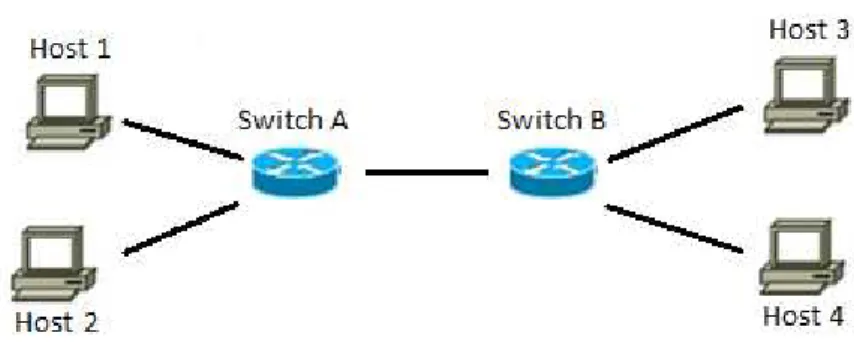
Example 1
The application in the first example implements the behaviour of a learning switch. A learning switch learns paths such that they do not flood (broadcast) excessively. They do this by learning the paths to the foreign MACs, and, upon receiving a packet destined to the foreign switch, they will only send out through the correct path.
To better explain, let us use the topology presented in Figure 3.1. Before any connection between the hosts, the two switches do not know any paths to any hosts. When Host 1 wants to send a packet to Host 4, it sends it to Switch A. Switch A will record which port Host 1 came in from. Since Switch A does not know where the MAC address for Host 4 is, it will flood and send a copy of the packet to both remaining ports. It will reach Host 2, but it will also reach Switch B. Switch B will save off how to get to Host 1 (via Switch A), and flood to hosts 3 and 4.
If, afterwards, Host 3 tries to send a packet to Host 1, Switch B will learn how to get to Host 3, will not flood and will send it directly to Switch A. Switch A will also learn how to get to Host 3 (via Switch B), and forward the packet directly to Host 3.
41
We will implement the behavior of a learning switch, and we will use three steps to complete it. The switches in our network will have only one rule: to send a Packet_IN message to the controller when a packet with an unknown destination is received. The three steps are three possible answers that the controller will send to the switches through a Packet_OUT message. We will start with the simplest, and least efficient until the most efficient. The steps represent the response of the controller after the reception of the Packet_IN message.
Step A: The controller sends a Packet_OUT message to the switch with the
action set to flood the original packet. Upon the reception of the Packet_OUT the switch floods the packet through all ports except the in port of the original packet. No flow entries are installed in the switch in this step. This is the behavior of an HUB.
Step B: First the controller will check its tables to see if it knows the
mapping for the desired destination. If the mapping was already learned by the controller app, the action is a forward action with the output port where the switch should send the packet. If the mapping is still not known the action is to flood the packet, as explained in Step A.
Step C: The controller makes the same verification as in Step B. If the
mapping is available, the controller app sends a Flow Modification message instructing the switch to add a Flow Entry rule that matches incoming packets with the learned incoming port / source MAC pair and an action to forward them to the learned output port. If the path was not learned yet, the controller will instruct the switch to flood the packet, as in the previous examples.
42
3.1.1.
Developing the floodlight module
The first step is to create a new class in floodlight. The class should be created in the “src/main/java” directory and it should be on its own Java package, the module can implement a number of different floodlight interfaces. In this example the module implements the IOFMessageListener and the
IFloodlightModule interfaces. IOFMessageListener is a message listener that gets notifications when the controller receives a packet. IFloodlightModule defines an interface for loadable floodlight modules, it is responsible to provide a template file when a new class is added, with the needed methods (which are empty) for a module to work. This interface is mandatory to develop a module for floodlight. After defining the implemented interfaces a new class is generated with the skeleton of a floodlight module. An example of the template file generated when a new class is created can be found in [21].
This automatic file generation happens if we use Eclipse, with a floodlight project compiled with ant. The virtual machine provided in floodlight’s site already has the floodlight project compiled. If the user does not want to use this virtual machine, the project can also be imported to Eclipse using the following commands on a terminal:
sudo apt-get install build-essential default-jdk ant
python-dev eclipse
git clone git://github.com/floodlight/floodlight.git
cd floodlight
ant eclipse
43
Finally, the module must be registered in floodlight for it to be loaded. This is done by adding the module name in two distinct files and it will be explained later.
3.1.2.
Emulating the network on Mininet
Mininet offers the possibility to initialize the topology via a Python script where the network elements such as switches, controllers and hosts are created and links between the elements are also defined. Some commands, such as ping,
pingAll, iperf, etc, can be launched automatically after the network starts, in the python script. Another option is to start Mininet in the CLI (Command-Line Interface) and write the commands as wanted.
For the first example we used the topology represented in Figure 3.2.
Figure 3.2: Topology used in Example 1
44
the links, how to start the network and two examples of how to run automatically a ping from Host 1 to Host 4 and a pingAll instruction. The command examples are only present to illustrate how to do it.
3.1.3.
Implementing the behavior step by step
We will start with Step A, where the controller sends a Packet_OUT message to the switch with the action set to flood the original packet. Upon the reception of the Packet_OUT the switch floods the packet through all ports except the in port of the original packet. No flow entries are installed in the switch in this step.
To implement the module we start with the class module skeleton code. The first step is to include the needed dependencies for the code to work. Next, the IFloodlightProvider object needs to be declared for registering with the Floodlight main module and a logger object is declared to output the events. This is achieved by adding the following lines in the module:
protected IFloodlightProviderService floodlightProvider;
protected static Logger log;
Next we need to tell the module loading system that we depend on it, which is done in the getModuleDependencies method:
public Collection<Class<? extends IFloodlightService>> getModuleDependencies() {
Collection<Class<? extends IFloodlightService>> l =
new ArrayList<Class<? extends IFloodlightService>>();
l.add(IFloodlightProviderService.class);
return l;
45
The init method loads the dependencies and initialize datastructures. It is called early in the controller startup process and it must be modified in order to get the controller instance and to create the logger, adding the following lines:
floodlightProvider = context.getServiceImpl(IFloodlightProviderService.class);
//get controller instance
log = LoggerFactory.getLogger(Example1a.class); //create logger class
When the controller receives a Packet-In it should be notified, therefore the listener must be implemented. The method startUp is where the message listener is registered by invoking the method addOFMessageListener and telling it we want to listen for events of type Packet_IN. The startUp method should be edited adding the following line:
floodlightProvider.addOFMessageListener(OFType.PACKET_IN, this);
It is also necessary to put an ID for the OFMessage listener. This is done in the getName call.
public String getName() {
return Example1a.class.getSimpleName();
}
46
get the information from the Packet_IN and sends a Packet_OUT message to the switch with the Actions set for flooding the packet.
An example of the module is available at [22].
Finally, the module should be registered in floodlight. This is done by adding the following line to the file in the following subdirectory of the floodlight project parent directory src/main/resources/META-INF/services/ net.floodlightcontroller.core.module.IFloodlightModule:
net.floodlightcontroller.exe1.Example1a
being net.floodlightcontroller.exe1 the Java package and Example1a the module’s name. It is also necessary to add the referred line into the properties file which can be accessed in src/main/resources/floodlightdefault.properties.
In Step B, the controller has a hash table where it collects the in port / source MAC address pair. After the reception of the Packet_IN message, the controller searches in the hash table for the destination MAC address. If the destination port for a MAC address is not in the table, it has to be stored and the controller sends a Packet_OUT message to the switch with the action set to flood. Upon the reception of the Packet_OUT the switch floods the packet through all ports except the in port of the original packet. In other hand, if the destination port for a MAC address is found, the controller sends a Packet_OUT message to the switch with the action set to send the packet through a specific port. No flow entries are installed in the switch in this step.
47
working with a hash table, two methods need to be created in order to save new information and to search information from the table. These methods are
addToPortMap and getFromPortMap. Comparing to step A’s code, the
processPacketInMessage method needs to be modified. It needs to get the information from the Packet_IN and search the hash table for the in port and MAC address in order to see if it already has this information or if it needs to save it. Then it will build the Packet_OUT message. If the destination port for the MAC address asked in the Packet_IN is not in the hash table, the Actions set in the Packet_OUT message sent to the switch will have a flooding action. If the destination port is found, the Actions set will have an action with the output port where to send the packet.
An example of this module can be found at [23].
The Step C is similar to Step B with the difference that a flow will be added in case the destination MAC is known by the controller.
48
idle timeout. When this timeout expires a message is sent to the controller, which has to analyze the outdated flow entry and send a FlowMod message instructing the switch to delete that flow entry.
To implement this behavior, the modifications will happen in
processPacketInMessage method which now needs to have the same functionalities as before, but now it also needs to write a FlowMod message. To achieve this, a new method must be developed, called writeFlowMod. This method will be called in the processPacketInMessage method. As it happens in step B if the destination port for the MAC address asked in the Packet_IN is not in the hash table, the Actions set in the Packet_OUT message sent to the switch will have a flooding action. If the destination port is found, the Packet_OUT message will contain a FlowMod adding a flow entry to that switch. When the flow entry expires the switch will send a message with that information, therefore in the startup method, we need to add a listener to this type of messages adding the following line:
floodlightProvider.addOFMessageListener
(OFType.FLOW_REMOVED, this)
In the receive method we need to contemplate this message type and call the processFlowRemovedMessage method. This method will send a FlowMod message instructing the switch to delete the expired flow entry:
case FLOW_REMOVED:
return this.processFlowRemovedMessage(sw,
(OFFlowRemoved) msg);
49
3.1.4.
Connect Mininet topology to Floodlight controller
After implementing the module on floodlight and creating the python file containing the topology, the controller should be started. Next, opening a terminal and navigating to the folder containing the topology file, the network can be started with the command:
sudo python *filename.py*
And, immediately, it is possible to see in the controller’s log the switches being added. To try the step A, a ping from Host 1 to Host 4 is made in order to force the switch to ask the path to the controller. Opening the python file it is possible to see the following lines:
h1= net.get('h1')
result = h1.cmd('ping -c4 10.0.0.4')
print result
This will make the desired ping automatically, just by running the script mentioned above. If preferred, these lines can be removed and the ping can be done manually in the CLI. The pingAll Example next should be removed in order to be clearer to see what is happening.
Opening an Xterm window for any switch (“xterm s1” on the terminal for
Switch 1) is possible to see the flow entries in the switch. On the Xterm window we can write:
sudo ovs-ofctl dump-flows s1 -O OpenFlow13
Resulting in the following output: