Environmental equalizer for underwater
communications
Ant´onio Silva and S´ergio M. Jesus
Institute for Systems and Robotics, Universidade do Algarve
Campus de Gambelas, PT-8005-139 Faro, Portugal
Email:
{asilva,sjesus}@ualg.pt
Jo˜ao Gomes
Institute for Systems and Robotics, Instituto Superior T´ecnico
Av. Rovisco Pais, PT-1049-001 Lisboa, Portugal
Email: [email protected]
Abstract
This paper presents an environmental-based equalization algorithm for underwater communications. This algorithm is based on the passive time-reversal (pTR) and waveguide invariant properties of ocean channels. Passive time-reversal allows for the implementation of a simple communications system, but it loses performance in the presence of geometric mismatch between the probe-signal and the actual data symbols transmission. The waveguide invariant properties state that geometric mismatches, both in depth and range, can be partially compensated by applying an appropriate frequency shift in the passive time-reversal operator. Results with binary PSK data at a carrier frequency of 3.6 kHz, collected during the MREA’04 sea trial, show that the Mean Square Error (MSE) between the transmitted and the received data symbols remains stable at least to a range mismatch of about 37.5 m in the presence of source depth and an array depth oscillations of approximately 0.7 m. In such conditions, when comparing the proposed pTR equalizer with plain pTR, an overall gain of approximately 4.11 dB in output MSE is achieved.
I. INTRODUCTION
In recent years Time Reversal (TR) has received particular attention from the scientific community. After practical demon-stration of its spatial-temporal focusing capabilities in the ocean [1] several applications of active TR (aTR), from tomography to communications, were suggested [1], [2]. Passive TR uses a receive-only array, and a probe-signal is transmitted ahead of the data for channel Impulse Response (IR) estimation. The IR estimate is then used as a synthetic channel for temporal focusing of the data signal, which is equivalent to the deconvolution of the multipath generated by the real channel.
When applied to underwater coherent communications the achieved TR focus is not perfect due to errors on the IR estimate and the time variability of the channel, resulting in uncompensated intersymbol interference (ISI) [3]. That problem is even more relevant in communications with a moving source and/or receiver. In that case it is intuitive that a rapid degradation of passive TR temporal focusing will occur due to the increasing mismatch between the assumed and actual channels. In order to guarantee a longer stability of the focal spot, three solutions are usually proposed: one is to transmit probe-signals more frequently; another is to use an adaptive algorithm to track the IR from the initial probe signal IR estimation; and finally a third alternative is to use a low-complexity equalizer with only one coefficient per channel. A performance comparison between those adaptive pTR variants is presented in [4]. The major inconvenient of the first method is that frequent transmission of probe-signals reduces the overall transmission rate. In the second the channel estimates are represented by a large number of coefficients that have to be adapted. The third case seems to be the best compromise between complexity and efficiency. In this paper a different approach is proposed by considering that the environment mismatch between the probe-signal and data transmission is mainly due to the geometric properties (source-array range, source depth and array depth), and that the knowledge of such mismatch can be used to compensate for the overall pTR IR mismatch between the probe-signal and actual data transmissions.
A physics-based algorithm for pTR equalization based on the waveguide invariant properties of the shallow water channel is proposed. The waveguide invariant property β [5] has been applied to change the aTR range focus in [6], and to interpret
a model for performance prediction of a time-reversal communication system [7]. In [8] a new waveguide invariant ζ was
identified, which, in conjunction with β, allows for the compensation of pTR geometric mismatch. Though this waveguide
invariants, changes on geometric features of the acoustic channel, such as source-receiver range, source depth and array depth, can be compensated by a frequency shift in the estimate IRs during the probe-signal transmission. The resulting Frequency Shift pTR (FSpTR) equalizer will increase the pTR output power, resulting in lower MSE. A physics-based equalizer for underwater communications that is able to detect the transmitted data sequence and to simultaneously estimate the source-array range, source depth and array depth is thus obtained.
The reliability of the physics-based waveguide invariant pTR equalizer is demonstrated using experimental data obtained during the MREA’04 sea trial, where binary PSK signals at a data rate of 400 bits per second were transmitted with a carrier
frequency of 3.6 kHz. Results obtained with FSpTR, after Doppler compensation of the received signals, show a long-term compensation of channel mismatch, with the MSE remaining stable up to a source-array range mismatch of about 37.5 m in the presence of source depth variations between 71.6 m and 72.3 m and an array depth oscillation of approximately 0.63 m. In such conditions, when comparing FSpTR with plain pTR, an overall gain of approximately 4.11 dB in output MSE is achieved.
The paper is organized as follows: Section II recalls the use of pTR in underwater communications; in Section III the pTR geometric mismatch compensation using frequency shifts is presented; Section IV develops the FSpTR equalizer, which is applied to real data in section V; Section VI summarizes the main results, draws some conclusions, and suggests future research.
II. PASSIVETIMEREVERSAL APPLIED TO COMMUNICATIONS
The basic setup for applying pTR to communications consists in a point source that sends information to a Vertical Line Array (VLA). The procedure starts by sending a short probe-signal, waiting for the channel to clear of multipath arrivals, and then sending the data stream. Considering the noise less case, the received probe and the data are processed in a TR fashion and it results that the pTR output, in its baseband version [9], is given by
y(t) = [a(t) ∗ p4(t)] ∗ pT R(t, ∆), (1)
where the lower∗ represents the convolution , [a(t) ∗ p4(t)] is the transmitted signal with raised-cosine pulse shape symbols;
pT R(t, ∆) is the resulting pTR IR acoustic field given by
pT R(t, ∆) = I
X
i=1
hi(t, ∆) ∗ h′∗i (−t), (2)
where and the upper∗ represents phase conjugation, i is the hydrophones index, h′
i(t) represents the channel IRs during probe
transmission, hi(t, ∆) is the channel IRs during data transmission, and ∆ represents a possible mismatch between h′i andhi.
In a shallow water waveguide and at a range greater than a few water depths the acoustic field generated by a monochromatic point source at the ith hydrophone of a VLA is given by the so-called Green’s function
Gω(r, z0, zi) = −j ρ√8πRe −jπ 4 M X n=1 Zm(zi)Zm(z0) √ km ejkmR, (3)
where m is the mode number, M is the total number of propagating modes, ρ is the (constant) water density, R is the
source-array range, Zm is the mth mode shape, z0 is the source depth, zi is the i-hydrophone depth, and km is the mth
mode horizontal wavenumber. In a range independent environment and under the adiabatic condition km andM are the only
quantities in (3) that depend on frequency ω. In the frequency domain the synthetic pTR IR acoustic field (2) in a stationary
environment (considering ∆ to be negligible) is given by [10]
Ppc(R, z0, zi, ω) = I X i=1 Gω(R, z0, zi)G∗ω(R, z0, zi) = 1 ρ28πR M X m=1 M X n=1 Zm(z0)Zn(z0) √ kmkn I X i=1 Zm(zi)Zn(zi)ej(kmR−knR) = 1 ρ28πR M X m=1 |Zm(z0)|2 |km| , (4)
where, for simplicity, it was considered thatZm(·) and kmare real quantities, which amounts to ignoring the leaky modes and
considering the loss mechanisms to be negligible [11]. Additionally, in (4) it was considered that the array spans the entire water column and that hydrophones depth sampling is sufficiently dense to fulfil the modal orthogonality property.
Sincekmin the denominator of (4) is a weak function of frequency,Ppc(·) is approximately constant. Thus in time domain
the pT R(·) given by (2) can be approximated by a pulse under convolution with the bandlimited transmitted sequence.
III. PASSIVETIMEREVERSAL GEOMETRIC MISMATCH COMPENSATION
When there is a geometric mismatch ∆ (∆r for source-array range, ∆z0 for source depth, ∆zi for array depth, or any
compensated by applying a frequency shift ∆ω to the other, and (4) becomes Ppc(·, ∆ω; ∆r, ∆z0, ∆zi) = I X i Gω(R + ∆r, z0+ ∆z0, zi+ ∆zi)G∗ω+∆ω(R, z0, zi) = 1 ρ28πR M X m=1 M X n=1 Zm(z0)Zn(z0+ ∆z0) √ kmkn X Zm(zi)Zn(zi+ ∆zi) ej(k† mR−kn(R+∆r)), (5) wherek†
m= km(ω + ∆ω), the influence of the frequency shift on the horizontal wavenumber km placed in the denominator
of (5) is neglected and the range shift is considered to be small enough so that R ≈pR(R + ∆r) in the denominator. In (5) it is relevant that the source-array range shift ∆r perturbs the exponential term, the array depth shift ∆zi perturbs the modes
orthogonality and the source depth shift ∆z0 perturbs the gain that is related with the focal spot depth in aTR (see [8] for
details). A full discussion of this perturbation mechanism is presented in [8] and [12]. From this discussion it turns out that the frequency shift∆ω used in (5) can be computed as
∆ω = ω
R(−∆rβ + ∆ziζi+ ∆z0ζ0), (6)
and is applied in (5) by considering the first order Taylor expansion
km(ω + ∆ω) ≈ km(ω) +
dkm(ω)
dω ∆ω, (7)
where the derivative of kmwith respect to ω represents the horizontal group slowness. In (6) β, ζi andζ0 are the waveguide
invariants related to∆r, ∆zi and∆z0, respectively. Sinceζi andζ0 have a similar nature, in the followingζ will be used to
represent both.
The invariantβ is a well-known invariant in the frequency/range plane [5] and is selected from a set of values
βmn= 1 vh,n − 1 vh,m 1 uh,n − 1 uh,m , (8)
where vh,m = ω/km is the horizontal phase velocity and uh,m is the horizontal group velocity of mode m. The selection
of β from the βmn set must take in consideration the best linear approximation in the least-squares sense of the horizontal
wavenumberkm using the horizontal group slowness for a limited number of of modesMe< M , that is,
km≈ −
dkm
dω ωβ+ω ρ β, (9)
whereβ represents the slope of the approximation and ρβ its offset. The invariantρβ is closely related withβ and is selected
in a set of values ρβ,mn= 1 vh,m + βmn 1 uh,m . (10)
With the approximation of km (9) the compensation of the range mismatch is straightforward since the range mismatch
∆r and the frequency shift compensation ∆ωgiven by (6) both affect (5) in the exponential term. Such compensation can be
applied to narrowband signals since β and ρβ are invariant with frequency, in a similar manner to the focal intensity range
shift for aTR proposed in [6].
The ζ waveguide invariants used for source depth ∆z0 and array depth∆zi compensation have been developed in [8] in a
similar manner to β, but for the approximation of the vertical wavenumber γmusing the horizontal group slowness
γm≈ −
dkm
dω ω ζ+ω ρ ζ, (11)
ζ is selected from a set of values
ζmn= 1 vv,n − 1 vv,m 1 uh,n − 1 uh,m , (12)
wherevv,m= ω/γmis the vertical phase velocity, and ρζ is selected in the set
ρζ,mn= 1 vv,m + ζmn 1 uh,m . (13)
The application of (11) in (5) for the source depth mismatch∆z0 and array depth mismatch∆zi compensation was made
possible after establishing that they can be partially compensated usingexp(jγm∆z0) and exp(jγm∆zi) respectively (see [8]
for details). That is, for source depth mismatch∆z0 compensation M X m=1 Zm(z0)Zm(z0+ ∆z0)ejγm∆z0 ≈ M X m=1 Zm(z0)Zm(z0) V (∆z0) 2 , (14)
where|V (∆z0)| ≈ 2 for small values of ∆z0 and|V (∆z0)| ≈ 1 for higher values of ∆z0. For the array depth mismatch∆zi
compensation I X i=1 Zm(zi)Zn(zi+ ∆zi)ejγm∆zi ≈ I X i=1 Zm(zi)Zn(zi) W (m, ∆zi) 2 , (15)
where|W (m, ∆zi)| ≈ 2 for small values of ∆zi and|W (m, ∆zi)| oscillates around 1 for higher values of ∆zi.
With the approximation of γm (11) and the compensation mechanisms (14) and (15) the compensation of the source and
array depth mismatches is straightforward since the mismatch can be compensated by a complex exponential of γm and the
frequency shift compensation ∆ω, given by (6), affects (5) in an exponential factor. Such compensation can be applied to
narrowband signals sinceζ and ρζ are invariant with frequency.
As previously suggested for the invariant β, the ζ compensation mechanism has a better performance when considering
an effective number of modes Me< M . The selection of β in (8) and ζ in (12) for optimal compensation depends on Me.
Such dependence suggests that the compensation mechanism can be further optimized by considering its application to smaller groups of modes instead of a single group of modes from m = 1, .., Me, resulting in different values of β and ζ for each
group. That was previously proposed in [6] and [13] for the waveguide invariantβ.
In a waveguide with a depth-dependent sound-speed profile the vertical wavenumber as well as phase velocity become depth dependent. In the present paper it is assumed that such dependence is small enough so thatζi can be calculated from the mean
phase velocity, vv,m(zi), over the array. Since ζ0 is computed for the nominal source depth z0 in a real situation it will be
expected thatζi6= ζ0.
IV. THE PASSIVE TIME-REVERSAL FREQUENCY SHIFT EQUALIZER
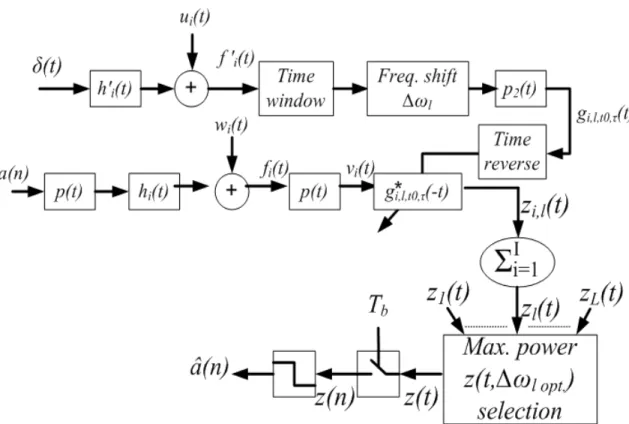
Figure 1 shows the pTR system adapted to incorporate a frequency shift that compensates for the geometric mismatch ∆
between the IR for probe-signal transmission h′(t) and the IR during data transmission h(t). It behaves as a matched filter
(to the IR) demodulator with a set of L frequency shifts being applied to the channel IR h′(t) estimate after time windowing,
where the optimal frequency shift is selected based on the “Maximum power selection” block with the zl(t) power being
computed in time slots. In figure 1 the pTR output signal can be written as
zl(t) = yl(t) + x1l(t) + x2l(t) + x3l(t), (16)
where index l designates frequency shift ∆ωl,yl(t) contains the desired data-signal contaminated with ISI and the other three
terms are noise disturbances (see [9] for definitions and details).
The overall Signal to Noise Ratio (SNR) ia a ratio between the variance of the signal termyl(t) and a sum of the variances
of the noise disturbances x1l(t), x2l(t) and x3l(t). It can be shown that the effect of the frequency shift compensation on
the channel IRh′(t) estimate is higher on the signal variance term than on the noise variances, therefore contributing to SNR
enhancement. Therefore, tracking the maximum power of the pTR output zl(t) gives a clear indicator of the best frequency
shift taking into account the actual environmental/geometric conditions of the signals being received. That results in the FSpTR system that equalize the real pTR IR PI
i=1hi(t) ∗ h′∗i,t0,τ(−t) (where the
′ indicates that there is a geometric mismatch ∆
between hi and h′∗i,t0,τ) with the non geometric mismatch pTR IR
PI
i=1hi(t) ∗ h∗i,t0,τ(−t), where t0 andτ are the starting
time and duration of the time window respectively.
V. REALDATAAPPLICATION
The experimental data were acquired during the MREA’04 sea trial that took place off the town of Set´ubal, approximately 50km south of Lisbon (Portugal), in April 2004. The pTR experiment started at a close range of 0.6km to the south of the receiving array (in a gently up sloping region) and the source progressively opened range to the southeast up to 2km (with a progressive slope reduction up to range independence). The environment was characterized by a water column depth ranging between 90 to 110 m over a 1.5 m silt bottom and gravel layer. The receiving array was free drifting in a surface suspended Acoustic Oceanographic Buoy (AOB) [14], which was found to oscillate vertically due to the surface waves with amplitude of approximately 0.63m and frequency between 0.43 and 0.4Hz, as measured by a wave rider buoy placed in the area of the experiment. The acoustic source was suspended from the NRV Alliance, its depth was measured at a sampling rate of 1 s with a 10 cm resolution depth sensor. In the data set processed in this paper it oscillates with a main component of 0.1 Hz, between 71.64 and 72.24 m.
Fig. 1. Block-diagram of the FSpTR equalizer. The blokes path above represent the probe-signal IRs estimate, time windowing, and frequency shift operations. The blokes path middle represents the data transmission and crosscorrelation with the IRs estimate obtained path above, the summation over the I hydrophones gives L pTR processor outputszl(t). The blokes path below represents the selection ofzl(t) with the frequency shift that best compensates for the geometric
mismatch between probe and data transmissions, and the transmitted symbols estimation.
During the MREA’04 sea trial the pTR based data communications conceptual system was similar to that of figure 1, with the p2(t) narrowband filter of the IR estimation operation (path above in figure 1) distributed between the transmitter and the
receiver, i.e., the transmitted probe-signal was a fourth-root raised-cosine pulse and IR estimates were obtained by correlating the received probe-signal with the transmitted one (see [3] for details).
This paper analyzes modulated data at a carrier frequency of 3.6 kHz, using a symbol rate of 400 baud and 2-PSK constellation. Fourth-root raised cosine signaling pulses with 100% roll-off were used such that the signal bandwidth is 800 Hz. Each individual transmission comprises a single truncated PAM signaling pulse acting as a channel probe with symmetric guard intervals for a total duration of 1 s, followed by a 20 s data packet. The source sequentially transmits 4 packets for a total duration of 84 s. In order to demonstrate the long-term stability of the proposed FSpTR compensation mechanism only the third channel probe pulse was used in the pTR operation of figure 1 to estimate the transmitted symbols in the four data packets. The data was preprocessed using the Doppler compensation method as proposed in [4].
Since the sound speed profile is composed of a thermocline of approximately 20 m and 1512 m/s over a down refracting sound speed up to approximately 1505 m/s near the bottom two different modal structures have been observed by the top two hydrophones and by the six bottom hydrophones [13] [8]. Those two modal structures are expected to have different invariants [13], and for the purpose of showing the usefulness of the waveguide invariant frequency shift in underwater communications with pTR in a geometric variable environment, only the six hydrophones below the thermocline were considered.
The system of figure 1 requires the use of a time window whose optimum length τopt, in a non geometric mismatch case,
has been found in [9]. The time window initial pointt0 is set to an arbitrary point before the first arrival and the time window
length τ is set to a value higher that the optimum in order to allow for a better behavior of the compensation mechanism in
presence of geometric mismatch. In the ray mode analogy [15] later arrivals are related with higher modes, making the time window operate as a mode filter.
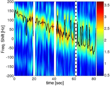
By considering the same frequency shift∆ωlto be applied to all modes captured in the time window(t0, τ ) in the system
of figure 1 the surface of figure 2 results. The surface represents the pTR output power σ2
z(t), computed in time slots of 0.5
s, as a function of time and frequency shift and the blank spaces represent the the elapsed time between the data slots. The solid line traces the maximum of the surface as a function of time, and the ‘*’ indicates the time instant where the channel probe used in the pTR processor was received. GPS data, acquired during the experiment, shows that during the 80 s of data transmission the source-array range increases by about 50 m, which can be clearly seen in figure 2 as a mean decrement of optimal frequency shift from about 150 Hz to about -50 Hz with 0 Hz at the channel probe location. Oscillations around the
mean increment seem to be mainly due to the other geometric mismatches (array depth and source depth), but no definitive conclusions can be draw since there is no ground truth information about array or source depth variations.
Fig. 2. Passive time-reversal output mean magnitude zl(t) as a function of time and applied frequency shift, computed by slots of 0.5 s. The solid line traces
the maximum of the surface.
Figure 3 shows the MSE between the estimated and the transmitted bit sequence, computed in slots of 0.5 seconds, for plain pTR with no compensation (solid line) and for pTR with compensation (red dashed line). The solid line initially shows a strong degradation in the uncompensated pTR that progressively reduces when approaching time of t = 60 s. Compensated
results (red dashed line) maintain the MSE at approximately the same level, resulting in a strong gain. In the first 20 s that gain is about 5.55 dB, in the second 20 s it is about 5.7 dB, in the third 20 s is about it 1.64 dB and in last 20 s it is about 1.53 dB, for an overall gain of about 4.11 dB. It is remarkable that such results were obtained with a range mismatch up to about 37.5 m with source depth varying between 71.6 m and 72.3 m and an array depth oscillation of approximately 0.63 m.
Fig. 3. Mean squared error between the estimated and transmitted data symbols for plain pTR (black line) and FSpTR (red dashed line).
VI. CONCLUSIONS ANDFUTURE WORK
Experimental results were given for time-reversed demodulation of 3.6 kHz binary PSK data collected during the MREA’04 experiment. Two receiving architectures were compared: plain pTR and pTR with frequency shift for geometric mismatch compensation - FSpTR. By itself, pTR suffers a significant performance penalty due to the geometric mismatch during the data
transmission resulting in acceptable results only a 20 s window around the channel probe location. FSpTR presents a longer stability that was shown to be effective for up to 60 s from the channel probe location. Moreover, FSpTR presents a gain of 1.5 dB over pTR even for short-term mismatch. Future work should address a comparison between FSpTR and other adaptive pTR systems [4].
Due to its environmental based nature, FSpTR can be used not only to attain reliable underwater communications, but also to track the geometric variations during data transmission considering a previous estimation of the waveguide invariants β, ζi
andζ0. Future experiments should be planed in order to explore such possibility.
In the present paper the Doppler compensation has been performed off-line previously to the equalization process. Future work should address its inclusion in the equalizer processor. In what concerns symbol synchronization, an heuristic method that chooses the minimal spread of the constellation previously to the slicer operation (slot by slot), was adopted.
ACKNOWLEDGMENTS
This work was supported by Fundac¸˜ao para a Ciˆencia e a Tecnologia under programs POCI, POCTI and POSI. The authors would like to thank the NATO Undersea Research Centre for the organization of MREA’04 sea trial, NRV Alliance master and personnel and the scientist in charge Emanuel F. Coelho.
REFERENCES
[1] W.A. Kuperman, W. Hodgkiss, H. Chun Song, T. Akal, C. Ferla, and D. Jackson. Phase conjugation in the ocean: Experimental demonstration of an acoustic time-reversal mirror. J. Acoust. Soc. Am., 103(1):25–40, January 1998.
[2] R.D. Jackson and R.D. Dowling. Phase conjugation in underwater acoustics. J. Acoust. Soc. Am., 89(1):171–181, January 1991.
[3] A. Silva and S. Jesus. Underwater communications using virtual time-reversal in a variable geometry channel. In Proc. MTS/IEEE Oceans’2002, pages 2416–2421, Biloxi, USA, November, 2002.
[4] J. Gomes, A. Silva, and S.M. Jesus. Spatial combining for passive time-reversed communications. submitted J. Acoust. Soc. America, March 2007. [5] G. A. Grachev. Theory of acoustic field invariants in layered waveguide. Acoust. Phys., (39):33–35, 1993.
[6] H. C. Song, W. A. Kuperman, and W. S. Hodgkiss. Time-reversal mirror with variable range focusing. J. Acoust. Soc. Am., 103((6)):3234–3240, June 1998.
[7] D. Rouseff. Intersymbol interference in underwater acoustic communications using time-reversal signal processing. J. Acoust. Soc. America, 117(2):780– 788, 2005.
[8] A. Silva, S.M. Jesus, and J. Gomes. Generalization of waveguide invariants and application to passive time reversal. submitted to J. Acoust. Soc.
America, July 2007.
[9] A. Silva, S.M. Jesus, and J. Gomes. Time reversal optimization for underwater communications. Submitted J. Acoust. Soc. America, April 2007. [10] D. Rouseff, D.R. Jackson, W.L.J. Fox, D.C. Jones, J.A. Ritcey, and D.R. Dowling. Underwater acoustic communications by passive-phase conjugation:
Theory and experimental results. J. Oceanic Engineering, 26(4):821–831, 2001.
[11] F. Jensen, W. Kuperman, M. Porter, and H. Schmidt. Computational Ocean Acoustics. AIP Series in Modern Acoustics and Signal Processing, New York, 1994.
[12] A. Silva, S. Jesus, and J. Gomes. Depth and range shift compensation using waveguide invariant properties. In Proc. of the UAM’07, Heraklion, Crete, Greece, June 2007.
[13] W.A. Kuperman, S. Kim, G.F. Edelmann, W.S. Hodgkiss, H.C. Song, and T. Akal T. Group and phase speed analysis for predicting and mitigating the effects of fluctuations. In Jensen Pace, editor, Impact of Littoral Environment Variability on Acoustic Predictions and Sonar Performance, pages 279–286, Kluwer, September 2002.
[14] A. Silva, F. Zabel, and C. Martins. Acoustic oceanographic buoy telemetry system. Sea Technology, 47(9), September 2006. [15] I. Tolstoy and C.S. Clay. Ocean Acoustics: Theory and experiments in underwater sound. AIP, New York, 1966.