Advances in Mechanical Engineering 2016, Vol. 8(4) 1–15
ÓThe Author(s) 2016 DOI: 10.1177/1687814016644577 aime.sagepub.com
Disturbance observer–based control
for missile non-strapdown seeker
disturbance rejection
Tao Song, Defu Lin and Jiang Wang
Abstract
Non-strapdown seeker disturbances which involve counter-electromotive force, spring restoring torque, and friction torque can corrupt the seeker tracking accuracy and degrade the missile guidance performance. In this article, the effects of guidance parameters and disturbances on the guidance stability and the miss distance are analyzed. It is shown that these disturbances have a pronounced deterioration in the guidance performance for the anti-air missile under high alti-tude and head-on interception. A new approach for disturbance rejection using disturbance observer–based control is presented. Disturbances in seeker stabilizing loop are estimated by the observer which has synthetic inputs based on the available seeker measurement signals. The estimates are fed back into the seeker inner loop to compensate the distur-bances, and an additional loop is applied to improve the effect of disturbance compensation. The performance of the approach under non-nominal condition is analyzed. Simulation studies are performed to examine the effect of this con-trol scheme. The result shows that this approach can effectively reduce the influences of corrupting disturbances and sig-nificantly improve the miss distance performance.
Keywords
Disturbance observer, seeker disturbance, missile guidance, stability, miss distance
Date received: 4 December 2015; accepted: 23 March 2016
Academic Editor: Nasim Ullah
Introduction
In the missile homing guidance, the line-of-sight (LOS) rate is required to achieve proportional navigation. This information is often extracted by the seeker, which is mounted in the front of the missile. The optical sen-sors (such as infrared (IR), television, and laser) have heretofore been used to detect target. To achieve a high tracking accuracy, the sensor axis should be stabilized to point toward the target regardless of the body motion of missile. In a single-plane analysis, the rele-vant angles are shown in Figure 1.
In Figure 1,eis the bore-sight error (BSE) angle that
is measured by the optical sensor,uris the gimbal angle
obtained by the angle sensor, q is the missile body angle,qsis the angle between the optical sensor axisxs
and inertial reference axisx, andqt is the line of sight
angle, respectively.
With different target tracking stabilization architec-tures, seekers are mainly divided into three types: non-strapdown seeker, semi-non-strapdown seeker, and fully strapdown seeker. In a non-strapdown seeker, the opti-cal sensor is suspended in a two-axis gimbal system, the measurementq_s of the rate gyro, which is mounted on
the gimbals and is used for tracking loop stabilization. The semi-strapdown seeker removes the rate gyro from the gimbals to satisfy the limits of the shape and vol-ume. The output q_ of the gyro located on the missile
School of Aerospace Engineering, Beijing Institute of Technology, Beijing, China
Corresponding author:
Tao Song, School of Aerospace Engineering, Beijing Institute of Technology, No. 5 Zhongguancun South Street, Beijing 10086, China. Email: [email protected]
body is combined with the measured gimbal angle ur
to stabilize the seeker tracking loop. The fully strap-down seeker straps the optical sensor on the missile body directly without using the gimbals, and the LOS rateq_tis estimated based on measurements of the body
angular rateq_ and the BSE anglee.
This article focuses on the disturbance rejection tech-nique based on the strapdown seeker. The non-strapdown seeker contains two feedback loops: tracking loop and stabilizing loop. Major functions of the track-ing loop are to maintain the BSE angleenear zero and
provide the desired LOS rate command to the stabiliz-ing loop. The stabilizstabiliz-ing loop is used to reduce the dis-turbances to stabilize the seeker despite base motion with high bandwidth. Traditionally, the LOS rate q_t is
directly approximated by the gyro measurement q_s.
With the advanced signal processing technique, an opti-mal estimator combines measurements of the BSE angle
e, rate gyro q_s, and gimbal angle ur to obtain a much
more accurate estimate of LOS rate. With the estima-tor, the guidance sensitivity to seeker disturbances can be greatly reduced depending on the quality of the mea-surements. To simplify the analysis, we assume that the LOS rate estimate is taken directly from the seeker gyro measurement in this article.
The seeker output is corrupted by several distur-bances during the flight, such as random error, noise, counter-electromotive force (CEMF), spring restoring torque (SRT), and friction torque (FT). Among these factors, CEMF, SRT, and FT introduce base motion into the seeker control system, corrupting seeker output accuracy and degrading missile precision.
The disturbance effect has been focused on for sev-eral years. The influence of radar radome slope error was first proposed by Nesline and Zarchan.1,2 Furthermore, the effect of the parasitic loop of semi-strapdown seeker induced by the CEMF, the friction coefficient, and the sensor dynamic mismatch on the stability and miss distance was analyzed by Song Jianmei.3 In the study by Taylor and Price,4 it was shown that the gimbal seeker tracking accuracy was quite sensitive to disturbance torque inputs. The miss distance was also given with the existence of seeker dis-turbance torque under nominal values of guidance parameters.5In guidance system design, guidance para-meters are normally determined without seeker distur-bances. However, the seeker disturbance effect may be amplified with unsuitable values of guidance para-meters. Therefore, the relationship between the missile guidance performance and main guidance parameters should be provided with the existence of gimbal seeker disturbances.
In practice, there are two ways to improve tracking accuracy in the face of seeker disturbances: the first is to increase the stabilizing loop gain6and the other is to insert a compensator in the stabilizing loop. However,
the stabilizing loop bandwidth is limited by hardware such as servo motor and rate gyro and also the seeker would become sensitive to sensor noise with these two methods. A seeker error-based loop decoupling filter was discussed by RN Bhattacharjee et al.,7and this fil-ter could significantly reduce seeker disturbances, but the seeker performance was decreased more or less because of high-frequency glitches. Chun-Liang Lin5 developed a feedforward control employing a multi-layer neural network to eliminate the seeker distur-bance torque.
Another approach is provided to handle this distur-bance problem using disturdistur-bance observer–based con-trol (DOBC). DOBC has been developed and applied in engineering in the recent years.8,9 In the DOBC approach, the disturbance is estimated by the distur-bance observer and then is used to compensate the dis-turbance effects by feedback or feedforward control. It can greatly reduce the disturbances without signifi-cantly changing the nominal performance of the exist-ing system. Smita Sadhu10 extended this method for LOS rate estimation by treating the input signal of the seeker as a disturbance. Although this extension simpli-fied the DOBC structure and did not require any addi-tional sensor, the estimated output is degraded by mismatch dynamics of the mathematic model with the physical system, which is evaluated in simulation.
This article focuses on the effect of seeker distur-bances (i.e. CEMF, SRT and FT) on missile guidance performance and then demonstrates a new control architecture that employs DOBC compensation to eliminate these disturbances. The disturbance estimates are extracted from available seeker measurement sig-nals and then applied to compensate the disturbance effects. The different architecture from the nominal DOBC is that an additional loop (AL) is added inside of the seeker stabilizing loop to improve the compensa-tion effect. The compensacompensa-tion effect is evaluated by the stability and miss distance analyses. The sensitivity of the performance of DOBC to seeker dynamic uncer-tainties is analyzed. Simulation results show that the seeker tracking quality and the guidance accuracy are significantly improved by the DOBC compensation approach.
Mathematical model of missile guidance
system with gimbal seeker
The simplified missile lateral guided model is shown in Figure 1. Definitions and nominal values of the model parameters are listed in Table 1. In Figure 2, the BSEe
is detected by the tracking sensor. The desired stabiliz-ing loop command is obtained by multiplystabiliz-ing the sen-sor output with the tracking loop gain K1. The motor
stabilizing loop command minus the gyro output, and this torque drives the motor to derive the BSE to error. The gyro outputq_s is used both as the stabilizing loop
feedback and the seeker output. The missile guided model is established under the following assumption.
Assumption 1. The guidance filter is a simple first-order dynamic system with the time constant Tg=4; the
autopilot is a first-order cubed transfer function with the same time constantTg=4.
Seeker glint noiseuGNof bandwidth1=TGNand
stan-dard deviation sGN is approximated by passing white noiseuw of power spectral density (PSD)FGN through
a first-order lag of time constantTGNwhere
FGN=2TGNs 2
GN ð1Þ
In Figure 2,^_qis the seeker output,Eais the
counter-electromotive,TM is the drive torque,TD is the
distur-bance torque,acis the acceleration command,amis the
missile acceleration, and other variables are defined in Table 1.
CEMF
CEMFEais the voltage caused by the magnetic
induc-tion line cutting moinduc-tion of the servo motor. It has the opposite polarity with the motor drive voltage, and its value is proportional to the gimbal rotation rate. The simplified CEMF model is
Figure 1. Angles in a single plane.
Table 1. Nominal values of guidance parameters.
Definition Nominal value
Tracking loop gain,K1 12
Stabilizing loop gain,K2 12
Motor resistance,R 8O
Motor torque constant,KT 0.2344 N m/A Motor moment of inertia,J 0.0020995 kg m2
Guidance gain,N 4
Guidance time constant,Tg 0.3 s Closing velocity,Vc 600 m/s Missile velocity,Vm 300 m/s Incidence lag,Ta 0.9 s
Guidance time duration,TF 5 s Glint noise time constant,TGN 0.15 s
Ea=KEu_r ð2Þ
where KE is the CEMF coefficient with unit V s=rad
andu_ris the gimbal rotation rate with unit rad=s.
SRT
SRT Ts is generated by the wire constraint during the
gimbal motion, and it is described as follows5
Ts=Ks,N
ur urlim
2n+1
ð3Þ
whereKs,N is the nonlinear spring coefficient with unit
N m, ur is the gimbal angle with unit rad, urlim is the
threshold value of gimbal angle with the nominal value 0.698 rad,nis a nonnegative integer, and different val-ues represent different types of SRT.
FT
The slip-stick FTTf is approximated as11
Tf=Kf,Nfð Þu_r ð4Þ
whereKf,Nis the nonlinear friction coefficient with unit
N m s=rad. Different selections ofu_r1andu_r2represent
various types of FTs, with unit rad=s (Figure 3(b)).
Effect of seeker disturbances on missile
performance
The SRT and FT are physically nonlinear, and for studying the effect of these disturbances on guidance performance, the disturbance torque can be simplified to the linear model, as shown in Figure 4.
In Figure 4, Ks andKf are linearized coefficients of
SRT and FT, with units N m=rad and N m s=rad, respectively.
The superposition principle is satisfied with the line-arized disturbance models; therefore, the seeker output
_
qscan be separated into two parts: the ideal seeker
out-putq_ according to the LOS rateq_tand the bias partDq_s
due to those disturbances. The equivalent missile gui-dance model without noise is shown in Figure 5. With the existence of disturbances, a parasitic loop is gener-ated inside missile guided system.
1 2
Figure 3. Nonlinear disturbance torque model: (a) spring restoring torque and (b) friction torque.
Figure 4. Linearized disturbance torque model.
Stability analysis of parasitic loop
The transfer function of the parasitic loop with LOS rateq_tinput and missile accelerationamoutput is
am
_ qt =
NVc
Tg
4s+1
4 NVc
Vm Tas+ 1 ð Þ Dq_s
_ q
ð5Þ
where Dq_s=q_ is the transfer function of missile body
rotational rate q_ input and the bias of seeker output Dq_sinduced by CEMF, SRT, and FT
Dq_s _
q =
KEKT+RKf
s+RKs
RJs2+ K
TK2+KfR+KEKT
s+RKs+KTK1K2
ð6Þ
The denominator of the equation is a sixth-order polynomial
DPL= RJs2+ KTK2+KfR+KEKT
s+RKs+KTK1K2
Tg 4s+1
4
NVc
Vm ðTas+1Þ KEKT+RKf
s+RKs
ð7Þ
The stability regions of the parasitic loop are ana-lyzed under assumption 2.
Assumption 2. The distance range between the missile and target is infinite, such that the time-to-go (TFt)
is big enough to treat the outer guidance loop open. For Tg=0:3, the stability regions of the parasitic
loop can be obtained via Routh Criterion, shown in Figure 6. The lines in Figure 6 represent boundaries of the stability regions. It can be seen that the stability regions will become smaller by (1) larger disturbance coefficients (KE,Ks, and Kf) and (2) increasing Ta, N,
andVc=Vm. The results also show that the missile
gui-dance system may even become unstable in the cases of high altitude (large Ta), head-on interception (large Vc=Vm), and large guidance gain (largeN).
Miss distance analysis
The miss distance is analyzed using adjoint method,12 and the adjoint model of guidance system is shown in Figure 7.
The ratio of miss distanceyGNand the square root of
the PSDFGN(RMDTSRPSD) is
RMDTSRPSD = yGN F1GN=2
= ðT
0
^ y2GNdt 2 4
3 5
1=2
ð8Þ
where yGN is the miss distance with glint noise input
andTis the rest guidance time.
Values of the parameters are shown in Table 1. Miss distances due to the glint noise are shown in Figure 8.
Figure 7. Adjoint model of missile guidance system.
The results show that the seeker disturbances would degrade the guidance accuracy. When the guidance sys-tem is stable, 5-s guidance time is sufficiently large to guarantee the miss distance reaching its asymptotic value.
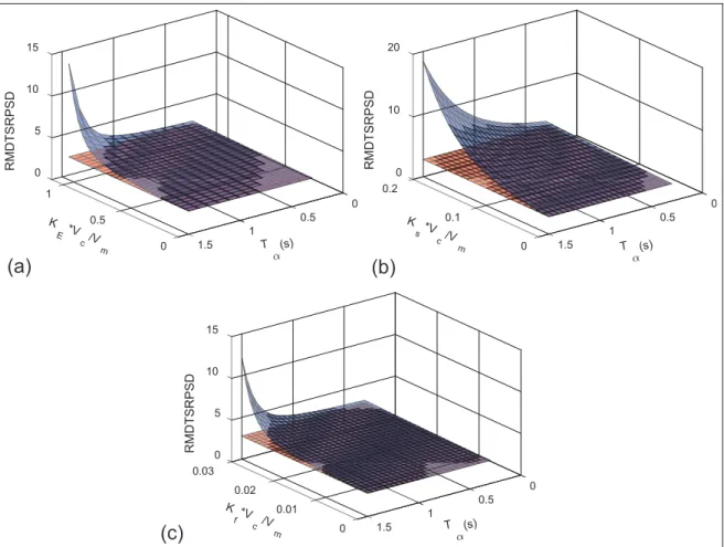
Assuming that Tg= 0.3 s and TGN= 0.15 s, the effect of the guidance parameters and the disturbances on miss distances for 5 s guidance time TF is given in Figure 11(a)–(c) (blue surface). It can be seen that the miss distance becomes larger with the increase in dis-turbance coefficients (KE,Ks,Kf),Vc=Vm, andTa. This
result coincides with the conclusion of stability analysis that the guidance performance will seriously deteriorate especially in the case of head-on interception and large guidance gain.
Disturbance compensation with DOBC
As described previously, seeker disturbances seriously degrade the guidance performance. Compensation must be included to enhance the seeker tracking accuracy.
CEMF, SRT, and FT disturbances can be integrated into an equivalent disturbance torqued
d=KT
R Ea+Ts+Tf ð9Þ
Typically, the DOBC generates an estimate of the disturbance^dand then uses it to compensate the distur-bance effects, shown in Figure 9(a).Pis the actual phys-ical system, Pn is the nominal dynamic model of the
physical system, G is a low-pass filter which is intro-duced to make thePn1Gphysical realizable, andrand
yare input and output signals, respectively. In this arti-cle,Gis chosen as
G= 1
TLFs+1
ð10Þ
It is easy to deduce the transfer function from distur-bancedinput toyoutput
y d=
Pð1GÞ 1G
ð Þ+GP=Pn
ð11Þ
The transfer function from inputrtoyoutput is y
r=
P 1G
ð Þ+GP=Pn
ð12Þ
Two cases—P=Pn=1 and P=Pn=0—are
considered:
1. IfP=Pn=1, equations (11) and (12) are
simpli-fied toy=d=P(1G), and y=r=P. It is clear that the disturbancedis filtered by a high-pass filter; therefore, the effect of disturbance at low
and moderate frequencies is reduced. Moreover, DOBC has no effect on seeker dynamics. 2. IfP=Pn=0, equations (11) and (12) are equal to
y=d=Pandy=r=P=(1G). The forward path gain of stabilizing loop is increased at low and moderate frequencies, which also reduces the effect of the disturbance on the seeker output.
The architecture of seeker disturbance compensation based on DOBC is presented in Figure 9(b). The observed value^dis estimated and fed back to the inner stabilizing loop, and the disturbance is further reduced by applying an AL (red dash line). In Figure 9(b),y1 is
the stabilizing loop error signal andy2 is the stabilizing
loop error signal after DOBC. Gs1 agglomerates the
transfer function fromy2 to the motor driving torque
Tm, andGs2is the motor loading transfer function.Gs1n
and Gs2n are the nominal values of Gs1 and Gs2,
respectively
Gs1n=K2KT=R, Gs2n=1=ð ÞJs ð13Þ
Without AL (red line) in Figure 8(b), the transfer functionGd1 of the seeker outputq_sto the disturbance
dinput is given by
Gd1=
Gs2ð1GÞ
1G
ð Þ+Gs1Gs2
K1
s +1
+ G
Gs1nGs2n
ð14Þ
It can be seen that if the bandwidth of the low-pass filter is infinite (G=1), Gd1jG=1=0, the disturbance
would be totally eliminated.
The transfer function Gd2=q_s=d with AL is
deduced
Gd2=
Gs2ð1GÞ
1G
ð Þ+Gs1Gs2
K1
s +1
Gs1nGs2n+1
ð Þ
+Gs1nGs2n+G Gs1nGs2n
2 6 6 4 3 7 7 5
ð15Þ
CompareGd2toGd1, asG=1
Gd2=
Gd1
Gs1nGs2n+1
ð16Þ
whereGs1nGs2n=K2KT=(JRs) is the nominal open-loop
transfer function of seeker stabilizing loop. Conventionally, to guarantee an enough stabilizing loop bandwidth, the open-loop gain should be suffi-ciently large. Therefore, the disturbance effect can be greatly reduced by AL.
The transfer functionGc=q_s=_qt of the LOS rateq_t
input to seeker outputq_swith AL is
Gc=
K1Gs1Gs2ðGs1nGs2n+1Þ
1G+G Gs1Gs2
Gs1nGs2n +Gs1Gs2+Gs1Gs2 Gs1nGs2n+ 1
ð Þ+K1Gs1Gs2ðGs1nGs2n+1Þ
h i
s
ð17Þ
Under the nominal condition, that is, Gs1=Gs1n,
Gs2=Gs2n, and G=1, q_s=_qt can be simplified to the
nominal value
Gc,n=
K1Gs1Gs2
1+Gs1Gs2
½ s+K1Gs1Gs2
ð18Þ
The above equation is equal to the ideal seeker dynamic function. It reflects that the disturbance com-pensation method does not change the seeker dynamics significantly. The only to-be-designed parameter is the time constant TLF of the low-pass filter. The choice of
the time constant TLF should balance between the
reduced disturbance and larger measurement noise effect. The higher open-loop gain of the stabilizing loop will also reduce the disturbance, but the gain is also limited by physical system (the servo motor and gyro bandwidth). By choosing TLF=0:01s, Tg= 0.3 s, the comparison of the parasitic loop stability regions with DOBC and without DOBC under the head-on intercep-tion (Vc=Vm=2) is presented in Figure 10. It is clear
that the stability of the parasitic loop is significantly improved with the ^d compensation based on DOBC, and the stability region is further increased by applying
A. The value ofTa generally falls within the range (0.1– 5 s), and the stability analysis result shows that the
compensation approach can guarantee the control sys-tem working within the stability region at a far target distance.
For Tg= 0.3 s, TGN= 0.15 s, and TF= 5 s, the improvement of missile guidance precisions with the DOBC compensation is presented in Figure 11. The guidance system is excited with glint noise uGN. The
guidance system with the DOBC compensation yields a remarkable decrease in the miss distance, and the gui-dance precision remains substantially unaltered with the increase in disturbance.
Sensitivity analyses under non-nominal
conditions
In practical applications, the seeker model may not be known exactly. Some unmodeled dynamics, such as fast dynamics of sensors and nonlinear dynamics of gimbal, perturb the seeker response from its nominal value and then derive estimation and compensation errors in DOBC. In this section, we discuss the sensitiv-ity of the performance of DOBC to seeker dynamic uncertainties.
The previous section indicates that DOBC is designed based on nominal valuesGs1nandGs2n of the
stabilizing loop; hence, the performance of DOBC is only sensitive to the deviations between real dynamics Gs1, Gs2 and their nominal values Gs1n, Gs2n. Without
loss of generality, the following assumptions of model uncertainties are satisfied in this study.
Assumption 3 (model uncertainties). Seeker model uncertainties are investigated by satisfying the following assumptions:
(a) Model uncertainties are considered to be gain perturbation and phase perturbation.
(b) Gain perturbation is presented by the additive uncertainty, and real dynamicsGs1andGs2can
be expressed by
Gs1=Gs1n+DGs1 and
Gs2=Gs2n+DGs2
ð19Þ
where DGs1 and DGs2 are dynamic
perturba-tions of Gs1 and Gs2, respectively, and
DGs1=Gs1n
j j and jDGs2=Gs2nj are small
quantities.
approximated by an equivalent time delay, and Gs1andGs2are rewritten as
Gs1=Gs1nej
vT1 and
Gs2=Gs2nej
vT2 ð20Þ
whereT1 and T2 are equivalent time delays of
Gs1 andGs2, respectively. Generally,T1 andT2
are small values, so that the phase perturbation v(T1+T2) within the gain crossover frequency
vsof stabilizing loop is less than 15°(0.25 rad).
(d) Effects of model uncertainties are analyzed within the frequency range0\v\vg, with vg
the gain crossover frequency of the seeker tracking loop.
Property 1 (seeker dynamics). In an acceptable design, the seeker dynamics satisfies the following properties within the frequency range (0,vg) of interest:
(a) The open-loop transfer function of the stabiliz-ing loop jGSLj=jGs1Gs2j would be a large
number, and its corresponding closed-loop transfer function jGSL=(GSL+1)j is nearly
unity.
(b) The amplitude of the seeker (or tracking loop) closed-loop transfer functionjGc,njin equation
(18) is close to unity, hence the amplitude of its open-loop transfer function j(K1=s)GSL=
(GSL+1)j 1.
(c) The gain crossover frequencyvsof the stabiliz-ing loop is much higher than vg, a reliable selection isvs;5vg.
The sensitivity relations of the performance of DOBC to dynamic deviations are presented by
_
qs=q_t=Gc,nð1Mc,xÞ and q_s=d=Gd,nð1Md,xÞ ð21Þ
whereMc,xandMd,xare sensitivity terms in the transfer
functionsq_s=_qtandq_s=dintroduced by the specific
per-turbation x, respectively; for additive perturbation x=add and for multiplicative perturbation x=multi denotes the specific perturbation; Gc,n is the nominal
value ofq_s=_qt given in equation (18); andGd,n is
Gd,n=
Gs2nð1GÞ
1G
ð Þ+Gs1nGs2n Ks1+1
Gs1nGs2n+1
ð Þ+Gs1nGs2n+G Gs1nGs2n
h i
ð22Þ
It is seen that smaller values of jMc,xj and jMd,xj
denote the closer performance of DOBC under the non-nominal condition to the non-nominal.jMc,xjandjMd,xjfor
additive and multiplicative perturbations within the fre-quency range0\v\vgare evaluated.
Additive uncertainty
Effect of additive uncertainty onq_s=_qt. Using equation (19),
the true open-loop dynamicGSLof stabilizing loop is
GSL=Gs1Gs2=Gs1nGs2n+DGSL=GSLn+DGSL ð23Þ
where GSLn=Gs1nGs2n is the nominal value of GSL;
DGSL is the perturb dynamic of stabilizing loop with
DGSL=Gs1nDGs2+Gs2nDGs1+DGs1DGs2.
Inserting equation (23) into equation (17) gives
_ qs=_qt’
K1GSL DGSL
GSLDGSL +
1+GSL
h i
s+K1GSL
=Gc,n 1 DGSL
s 1+GSL
ð Þs+K1GSL
½ ðGSLDGSLÞ
ð24Þ
Mc,add’ D
GSLs
1+GSL
ð Þs+K1GSL
½ ðGSLDGSLÞ
ð25Þ
Note that with Property 1(b), it is easy to prove that (j1+GSL)s+K1GSLj’jK1GSLj. Combining
prop-erties 1(a) and 1(b) gives jK1=vj 1. Equation (25)
becomes
Mc,add
j j’ DGSL
v
K1G 2 SL
DGSL
G2 SL
ð 26Þ
Mc,add
j jis expected to be a very small quantity, asjGSLj
would be a large number.
Figure 11. Comparison of miss distances with and without DOBC: (a) CEMF, (b) SRT, and (c) FT.
RMDTSRPSD is the ratio of miss distanceyGNto the square root of the PSDFGN. Blue surface: miss distance without DOBC; red surface: miss
Effect of additive uncertainty on q_s=d. Inserting equation
(19) into equation (15) gives
_ qs=d=
1G ð Þ
1G
ð Þ
Gs2n+DGs2 +ðGs1+DGs1Þ
K1
s +1
Gs1nGs2n+1
ð Þ+1+ G Gs1nGs2n
h i’Gd,n 1 DGs1
Gs1n
ð27Þ
Md,add’D
Gs1
Gs1n
ð28Þ
Under Assumption 3(b), jMd,addj’jDGs1=Gs1nj is a
small quantity. A practical simulation is shown in Figure 12(b).
Multiplicative uncertainty
From equation (20), the true dynamicsGs1andGs2are
Gs1=Gs1nej
vT1
’Gs1nGs1njvT1 ð29Þ
Gs2=Gs2nej
vT2
’Gs2nGs2njvT2 ð30Þ
GSL=GSLnej
vðT1+T2Þ
’GSLnGSLnjvðT1+T2Þ ð31Þ
Effect of multiplicative uncertainty on q_s=q_t. Combining
equations (31) and (26) gives
Mc,multi
j j vðT1+T2Þ GSL ð 32Þ
In equation (32), jGSLj is large. Assumption 3(c)
shows thatv(T1+T2) is a small number, typically less
than 0.25 within vs. It would be much smaller than 0.25 within the frequency range of interest, asvsvg. Consequently,jMc,multijwould be small.
Effect of multiplicative uncertainty onq_s=d. From equation
(28), we have
Md,multi
j j jvT1j ð33Þ
vT1 is a small quantity which is much less than 0.25
within the frequency band (0,vg). Therefore, jMd,multij
is a small value. The analysis result is evaluated by the simulation, shown in Figure 12(c).
Case study
First, the seeker response is analyzed without consider-ing both the outer parasitic loop and the guidance loop. Then, the parasitic loop is added into the discussion. Finally, the miss distance is simulated for the whole gui-dance system. Values of the parameters are shown in Table 1, and nonlinear disturbances are chosen as equa-tions (3) and (4). Three sets of nonlinear disturbance coefficients are employed, shown in Table 2.
Seeker response simulation
Without considering the outer parasitic loop and the guidance loop, the single seeker can be considered as a two-input one-output system with the LOS rateq_t and
base rotational rateq_ input and the outputq_s.
Values of disturbances are chosen as the first set in Table 2, and the time constant of the low-pass filter is TLF=0:01s. Now consider a platform rotational rateq_
is 2 Hz sine wave of 30°/s amplitude. LOS rate q_t is 0.2 Hz, square ware of 10°/s amplitude.
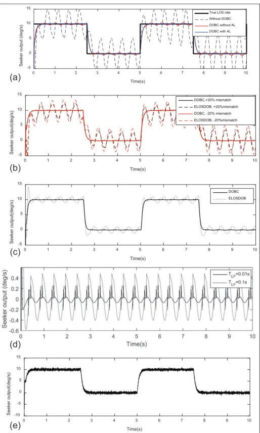
The seeker outputq_swith DOB compensation under
nominal condition is shown in Figure 12(a). It is seen that this approach with DOB compensation can be effective in eliminating the disturbance.
The sensitivity of this approach to the deviation of nominal open-loop transfer function Gs1nGs2n is
checked. It is assumed thatGs1nGs2nhas 620%
devia-tion, which is
Gs1nGs2n=1:2Gs1Gs2 or 0:8Gs1Gs2 ð34Þ
Smita Sadhu10used simplified DOB method to elimi-nate the effect of disturbances on the seeker outputs. In this approach, the true LOS rateq_tis treated as the
dis-turbanced, and it is estimated by the observed valued.^
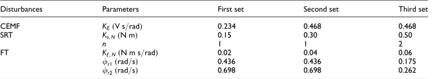
Table 2. Parameters of nonlinear disturbance.
Disturbances Parameters First set Second set Third set
CEMF KE(V s=rad) 0:234 0.468 0.468
SRT Ks,N(N m) 0.15 0.30 0.50
n 1 1 2
FT Kf,N(N m s=rad) 0.02 0.04 0.06
_
ur1(rad=s) 0.436 0.436 0.175
_
ur2(rad=s) 0.698 0.698 0.262
The difference between the estimator and the standard DOBC is the observed value^d and is not fed back to the control loop (red line of Figure 9(a)). Comparison of estimated LOS rate with DOB (ELOSDOB) is pre-sented by Sadhu10and seeker output with DOBC is illu-strated in Figure 12(b). With the deviation from the nominal case, ELOSDOB result significantly corrupts. It shows the output with DOBC is insensitive with the nominal parameters uncertainty.
The results of simulation with 20-ms time delay in stabilizing loop by two methods are shown in Figure 12(c). The similar conclusion shows an outperformance for DOBC.
According to the transfer function of the seeker out-putq_ to the disturbance d, the bandwidth of the low-pass filter greatly influences the disturbance rejection effect. This phenomenon is shown in Figure 12(d) (without measurement noise). With the larger value of TLF, the bigger seeker output induced by disturbance
occurs. The choice of filter parameter should obtain a trade-off between the disturbance rejection and the measurement noise effect.
With zero mean, 0.3°/s standard deviation band-limited (10 Hz) white seeker gyro measurement noise, the seeker output is shown in Figure 12(e).
Parasitic loop response simulation
The analysis of the parasitic loop response is to check the seeker output and missile acceleration response to the LOS rate input with the closed disturbance feed-back loop.
The guidance parameters are listed in Table 1. With 0.2 Hz, square ware of 10°/s amplitude LOS rate q_t input, the seeker outputq_sis given in Figure 13(a), and
the missile acceleration am is shown in Figure 13(b).
Without DOBC compensation, the seeker output q_s
diverges rapidly, resulting in a divergent acceleration response. This situation is greatly improved by DOBC compensation, and the seeker output error is effectively eliminated. The acceleration with DOBC compensation coincides with the guidance system without disturbances.
Miss distance simulation
The whole missile guidance system is analyzed to evalu-ate the effect of the DOBC compensation approach on miss distance. Three sets of nonlinear disturbances shown in Table 2 are employed.
The guidance time duringTFis 5 s. The guidance
sys-tem is simulated with the initial condition of 10°leading angle deviation and glint noise input. The glint noise is generated by a white noise entering a low-pass filter 1=(T
GNs+1), whereTGNis the glint noise time constant
given in Table 1. The standard deviation of glint noise is 0.5 m. The PSD FGN=2TGNs
2
GN=0:075(m 2
=Hz). The seeker gyro measurement is corrupted by zero mean, 0.2°/s standard deviation band-limited (10 Hz) white seeker.
Figure 14(a) illustrates the result of the disturbance observer output d. It shows that in the case of DOB^ compensation control, the disturbance observer suc-cessfully generates a compensation signal d^
approximating the disturbance d for all disturbance sets. Figure 14(b) is the seeker output with DOB com-pensation. After the compensation, the most part of disturbances are reduced sufficiently, and their effect to the seeker output is eliminated. Seeker outputs with DOBC for different disturbance sets coincide with each other.
Monte-Carlo guidance simulation has been used to calculate miss distance as a function of engagement time with glint noise input. For each disturbance set shown in Table 2, the guidance time changes from 0 to 5 s with 0.1-s time step, and 1000 simulations are applied for each time step. The miss distance at each time step is obtained by averaging the 1000 simulation results. Miss distances are shown in Figure 14(c). It is obvious that miss distances are greatly reduced by the DOBC compensation approach.
Conclusion
The effect of seeker disturbances, which involve CEMF, SRT, and FT, on missile guidance stability and
miss distance has been studied in this article, and the relationship between guidance performance and main guidance parameters is provided. The analysis shows that the guidance performance would be degraded by these disturbances, especially in situations of large gui-dance coefficient and head-on interception.
A new approach for disturbance rejection in seeker stabilizing loop using DOBC technique has been pre-sented. This observer can estimate the disturbance accurately; with the compensation of DOBC, the dis-turbance is greatly reduced. Different from the normal DOBC architecture, an AL is added inside the seeker stabilizing loop to improve the compensation effect. The stability and miss distance analyses are repeated to evaluate the compensation effectivity. This scheme does not require any additional sensor. The sensitivity analy-ses are presented to investigate the effects of model uncertainties on the performance of proposed approach.
Simulation studies are performed to assess the per-formance of this compensation method. Compared to the case without compensation, the results show that
this compensation controller can provide a significant improvement in seeker tracking accuracy and greatly reduce the missile miss distance.
Acknowledgements
The authors would like to thank the reviewers for their valu-able suggestions.
Declaration of conflicting interests
The author(s) declared no potential conflicts of interest with respect to the research, authorship, and/or publication of this article.
Funding
The author(s) received no financial support for the research, authorship, and/or publication of this article.
References
1. Nesline FW and Zarchan P. Missile guidance design tra-deoffs for high-altitude air defense. J Guid Control Dynam1983; 6: 207–212.
2. Nesline FW and Zarchan P. Radome induced miss dis-tance in aerodynamically controlled homing missiles. AIAA paper 84-1845, 1984, pp.99–115.
3. Jianmei S, Gaohua C and Lixia K. Precision analysis of the semi-strapdown homing guided system. AIAA paper 2012-4687, 2012, pp.1–14.
4. Taylor JH and Price CF.Direct statistical analysis of mis-sile guidance system via CADET. TASC Technical report, TR-385-3, 1976. Billerica, MA: The Analytic Science Co. 5. Lin C-L and Hsiao Y-H. Adaptive feedforward control for disturbance torque rejection in seeker stabilizing loop.IEEE T Contr Syst T2001; 9: 108–121.
6. Michael MK. Applications of control theory to design of line-of-sight stabilization system. In: American con-trol conference, Boston, MA, 19–21 June 1985, pp.1219–1222.
7. Bhattacharjee RN, Rao TV, Sadhu S, et al. Control structures and properties of missile seekers. J Inst Eng
2002; 82: 253–261.
8. Chladny RR and Koch CR. Flatness-based tracking of an electromechanical variable valve timing actuator with disturbance observer feedforward compensation.IEEE T Contr Syst T2008; 16: 652–663.
9. Greiser S. Disturbance observer-based control to sup-press air resonance for the EC135 ACT/FHS Research Helicopter. AIAA paper 2015-0856, 2015.
10. Sadhu S and Ghoshal TK. Sight line rate estimation in missile seeker using disturbance observer-based tech-nique.IEEE T Contr Syst T2011; 19: 449–454.
11. Haessig DA Jr and Friedland B. On the modeling and simulation of friction. J Dyn Syst: ASME 1991; 113: 354–362.