Development of an Interface for Ontology-based transformation
between
Features of different Types
W.M.T. Harshi Weerasinghe
A dissertation submitted in partial fulfillment of the requirements for the degree
of
Master of Science in Geospatial Technologies
FEBRUARY 2009
Westfälische Wilhelms-Universität Münster (WWU), Institute for Geoinformatics (ifgi), Germany,
Universitat Jaume I (UJI), Castellón, Dept. Lenguajes y Sistemas Informaticos (LSI), Spain and
APPROVED BY:
Prof. Dr. Werner Kuhn
Professor
Institute for Geoinformatics (ifgi) University of Muenster
Weseler Strasse 253
D-48151 Münster, Germany Email: [email protected]
Prof. Marco Painho
Director
Instituto Superior de Estatística e Gestão de Informação Universidade Nova de Lisboa
Campus de Campolide 1070-312 Lisboa - Portugal Email: [email protected]
Mr. Sven Schade
Graduate Assistant
Institute for GeoInformatics, Institute for Geoinformatics (ifgi) University of Muenster
Weseler Strasse 253
Affectionately Dedicated
To
My Beloved Parents, Sister
And
ACKNOWLEDGEMENT
My foremost and sincere thanks are due to Prof. Dr. Werner Kuhn, Professor, Institute for
Geoinformatics (ifgi), University of Muenster for his valuable guidance and continuous
encouragement extended to me throughout this study in accomplishing this enormous task
successfully.
I am also grateful to Prof. Marco Painho, Director, Instituto Superior de Estatística e Gestão de
Informação, Universidade Nova de Lisboa for his invaluable comments and encouraging guidance.
I appreciate in high esteem the supervisory guidance, encouragement and appropriate directives
received continuously until the completion of this thesis from Mr. Sven Schade, Graduate Assistant,
Institute for Geoinformatics (ifgi), University of Muenster.
I express my sincere and wholehearted gratitude to all academic and non-academic staff members of
the Institute for Geoinformatics, University of Muenster for providing me necessary facilities to
conduct my research at the Institute.
Finally my earnest thanks are due to my beloved parents, sister and friends for their unstinted
support, assistance and encouragement during this period, although they are thousands of miles
ABSTRACT
Implementation of the INSPIRE directive, the spatial data infrastructure for the Europe, has created a
necessity for easy and convenient conversion between different models of geospatial data. Data
model transformation across heterogeneous systems can be hampered by differences in terminology
and conceptualization, particularly when multiple communities are involved. Requirement in current
situation is an interface facilitating transformation of data to a desired format and immediate use of
the data, which are collected from different formats and models. Ontology-aware software with
shared understanding of concepts, enable users to interact with geospatial data models. Thus use of
ontologies could make a friendly environment to the user in translating the data conveniently.
Feature type ontologies, along with annotations are provided from an ongoing project at the Institute
for Geoinformatics (IfGI, University of Münster, Germany), in order to reconcile differences in
semantics. FME workbench provides a successful environment to execute set of rules for the data
model transformation using a mapping file, which can be developed externally. The thesis work
developed a user interface that includes operations to define rules for the translation of geospatial
data, from one model to another. Annotated feature types are taken as input, and the results are
encoded as FME Mapping files. The overall methodology involves three phases. Namely:
development of the interface, test execution with sample data, usability test. In the development
phase, the interface is designed with requirements identified in the literature survey. In the second
phase the interface is verified for its proper functionality by executing the transformation on the trial
data-set using two sample ontologies. The user-friendliness of the interface was evaluated by
conducting a usability test. The GUI is named as Ontology Based Schema Mapper (OBSM), consisting four main components; Mapping Component, Ontology Repository, Rules Repository and Rule
Generator. The functionality of the OBSM could be expressed as follows. The initial stage of the procedure imports the annotated feature types of the source data model to the system, while saving
a copy in the Ontology Repository. Then two alternative options are given to the user; either to
define new rules of transformation or to retrieve existing set of rules for transformation. If the user
selects to define new rules, the target annotated feature type is also imported to the system. The user
can generate OBSM mapper file, for the set of defined rules using the Rule Generator and save a copy in the Rules Repository or export to a desired location. The interface was tested with feature types
used within the INSPIRE context. In the trial execution of the transformation, the source feature types
are from the ATKIS data model and the translation rules are defined to translate into the INSPIRE data
model for transport networks. The tool was evaluated for its usability, following principles for a
heuristic evaluation. The evaluation was performed using a questionnaire and a prototype of the tool
within a group of experts. Results proved that the users identify the tool as a convenient and easy to
CONTENTS
ACKNOWLEDGEMENT...I
ABSTRACT ... II
CONTENTS... III
LIST OF FIGURES ... IV
LIST OF TABLES ... V
1 INTRODUCTION...1
1.1 MOTIVATION...1
1.2 PROBLEM STATEMENT...2
1.3 RESEARCH METHOD...2
1.4 CHAPTER ARRANGEMENT...3
2 BACKGROUND ...4
2.1 INSPIRE DIRECTIVE ON SPATIAL DATA INFRASTRUCTURE (SDI)...4
2.2 SEMANTIC WEB AND ONTOLOGY LANGUAGES...5
2.3 SEMANTIC ANNOTATION OF FEATURE TYPES...6
3 INTRODUCTION TO THE OBSM TOOL ...9
3.1 INTRODUCTION TO THE GENERAL SCENARIO...9
3.2 SCOPE OF THE TOOL...10
3.3 ACTIVITY DIAGRAM...11
3.4 OPERATION OF THE TOOL...13
3.5 COMPONENTS OF THE TOOL...20
3.6 SEQUENCE DIAGRAM...22
3.7 EVALUATION OF THE TOOL...23
4 APPLICATION OF THE TRANSLATION TOOL ... 27
4.1 DATA MODELS USED IN EVALUATION...27
4.1.1 ATKIS-"AUTHORITATIVE TOPOGRAPHIC CARTOGRAPHIC INFORMATION SYSTEM"...27
4.1.2 INSPIREDATA SPECIFICATION ON TRANSPORT NETWORKS...28
4.2 ANNOTATION OF THE FEATURE TYPES TO THE DOMAIN ONTOLOGY...29
4.3 USE OF DATA IN THE TOOL AND RESULTS OBTAINED...31
5 CONCLUSIONS AND FUTURE WORK ... 37
REFERENCES ... 39
APPENDIX... 42
(A). EVALUATION QUESTIONNAIRE...42
(B). CONCEPT RENDERING ALGORITHM...43
LISTOFFIGURES
Figure 2.1: Overview of items involved in the process of annotating ontologies
in the context of WSMX (Schade, 2008; modified ...7
Figure 2.2(a): Syntactical Mapping using conventional schema mapping tools...8
Figure 2.2(b): Syntactical Mapping using conventional Feature Manipulation Engine (FME)...8
Figure 3.1: Components and the workflow of the architecture (Beckmann, et. al, 2009)...10
Figure 3.2: Communication of the tool with external resource components ...11
Figure 3.3: Activity Diagram of OBSM...12
Figure 3.4: Opening screen of the tool...13
Figure 3.5: First step of the process...14
Figure 3.6(a): First option in the second step of the process ...14
Figure 3.6(b): Second option in the second step of the process ...15
Figure 3.7(a): Arrangement of the objects in the third step of the process ...16
Figure 3.7(b): Rendering view of the ontology by the GUI...17
Figure 3.7(c): Second phase in the third step of the process ...18
Figure 3.7(d) presents the structure of the sample ‘OBSM Mapping file’...19
Figure 3.8: Forth step of the process...19
Figure 3.9: Sequence Diagram of OBSM ...23
Figure 4.1: ATKIS data model architecture (Source: Hesse, 1990) ...27
Figure 4.2: The relationship of the data specification with supporting information architecture (Source:D2.8.I.7 Data Specification on Transport networks)...29
Figure 4.3: Annotated feature type ontology ...30
Figure 4.4(a): Selecting the source feature type ontology file ...31
Figure 4.4(b): Extracting the source feature types ...32
Figure 4.5(a): Selecting the source feature types – alternative 01...32
Figure 4.5(b): Selecting the Target feature types - alternative 02 ...33
Figure 4.5(c): Extracting the source feature types - alternative 02...34
Figure 4.6(a): Rendering and navigation trough concept maps...35
Figure 4.6(b): Definition of a mapping record ...35
Figure 4.6(c): Generation of the OBSM mapping file ...36
LISTOFTABLES
Table 3.1: Schematic representation of the rules definition table...20
Table 3.2: Results obtained for the section 01 of the questionnaire...25
(Percentage of votes from the total responses)
Table 3.3: Results obtained for the section 02 of the questionnaire ...26
1 INTRODUCTION
The first chapter introduces the problem of Graphical User Interfaces (GUIs) for schema mapping,
and the requirements that GUIs should fulfill in order to cater the existing problem. The chapter ends
with a description of the structure of the thesis.
1.1 Motivation
Emergence and the implementation of the INSPIRE directive (Directive, 2007), the spatial data infrastructure for Europe, increased the necessity for easy and convenient communication between
different structures of geospatial data. The initiative intends to trigger the creation of a European
spatial information infrastructure that delivers to the users integrated spatial information services.
These services should allow the users to identify and access spatial or geographical information on a
wide range of sources, from the local level to the global level, in an interoperable way for a variety of
uses.
Schemas express shared vocabularies and allow machines to carry out rules, which provide a
means for defining the structure, contents of XML documents (McQueen et al., 2008). XML is a concept used in web based data services, which stands for Extensible Markup Language and
designed to transport and store data, with focus on what data is (W3Schools, 2009). Data model transformation across heterogeneous systems can be hampered by differences in terminology and
conceptualization, particularly when multiple communities are involved. Software tools have been
developed in order to transform data from one data model to another, using graphical and command
line interfaces (Moore, 2007). The ‘GO Publisher’ (Snowflake, 2008), ‘Feature Manipulation Engine’
(Safe, 2009) and ‘GeoXSLT’ (Klausen, 2006) are some of the software tools available for feature type
(ISO, 2005) translation, in which translations are most often, based on a data-store, using abbreviated names of tables and attributes. Data models can be translated from one model to the other using
conversion operations, which are referred to as schema mapping.These defined operations are called
as rules of transformation (Paolo et al., 2007). This enforces the users for a comprehensive understanding of large documentation on data models to a greater extent and complex programs
that work on the data model mapping (Florescu and Kossmann 1999).
“To be able to understand and reuse the components easily, some extra knowledge about
the components is needed. This extra knowledge is called as the ‘component meta-knowledge’. The
component meta-knowledge for different domains is modeled by the domain ontologies” (Erdur and Dikenelli 2002). “Semantic matchmaking can be hence described as the process of computing an ordered list of appealing resource taking into account also the semantics of resources annotation and
making (Moran et. al 2005, Melnik, 1999).Yet the domain ontologies are more significant to utilize in interoperability approaches. In most cases this fact is important when considering the semantic
interoperability between different concepts in different application domains.
1.2 Problem Statement
Manually specifying schema mapping with abstracted attribute names is a time-consuming,
error-prone and therefore an expensive process (Lutz et al., 2006). Yet the most crucial factor is that these software tools must handle in a carefully tuned manner to get a reasonable result. Another
limitation is that the users need a comprehensive knowledge about the semantics of geospatial data
models under consideration (Kuhn 2005). The time required in optimizing the use of the programs and the understanding of data models is hindrance for applications, where results need to be evolved
with lesser effort. Moreover, there is a linear relation between the level of effort and the number of
matches to be performed, which can be considered as a growing problem due to the rapidly
increasing number of web data sources and e-businesses to integrate (Volker et al., 2006). Thus the requirement for a faster and less labor-intensive integrative approach is justified. However, the
restrictions in syntactical mapping process can be summarized as;
○ An in-depth knowledge of both the source and target schemas is required in advance. Schemas need to be studied in detail before mapping. This is a very expensive step and cannot be avoided
in actual project implementation.
○ Mappings are often hard to understand and error-prone because humans normally think in terms of the semantics instead of the syntax – e.g. person is rather likely to map two pieces of
information (Line segment to road segment) rather than two mapping elements (EI 23434 to SG 56543).
○ Mapping rules, typically cannot be reused, because they are tool dependent and must be created from scratch when a new schema mapping is defined.
○ Concepts such as inheritance and logical constraints are not supported.
Therefore the main goal of the work can be summarized as : the development of an interface which translates data from one model to another, with a set of predefined rules in translating the schema based on ontologies of the two data models in which the functionality will be tested in the INSPIRE data model context.
1.3 Research Method
The work will develop a tool, which includes operations to define rules for the translation of
geospatial data, from one feature type to another. The tool is named as ‘Ontology Based Schema
OBSM Mapping component, OBSM Rule Repository and OBSM Rule Generator. Activity diagram, sequence diagram presents the operations arranged within these four components inside the tool
architecture.
The overall methodology involves three phases. Namely; development of the tool, test
execution with sample data and a usability test. In the development phase, the tool is designed with
requirements identified in the literature survey. In the second phase the tool is verified for its proper
functionality by executing the transformation on the trial data set using two sample ontologies. The
study also includes a usability test to evaluate the tool for its user-friendliness by conducting a
usability test.
The functionality of the tool can be expressed as follows. The initial stage of the procedure
imports the annotated feature types of the source data model to the system. After the system checks
the validity of the retrieved feature type name spaces, option is given to the user to define new rules
of transformation or use of existing rules of transformation. If the user selects to define new rules, the
target annotated feature types are also be imported to the system. In the next stage the user can
save the used rules of transformation for future use and perform actual transformation on the data
set.
The GUI is tested with feature types used within the INSPIRE context. In the trial execution of
the transformation, the source feature types are from the ATKIS data model (Grünreich 1992) and the data are transformed into the INSPIRE data model for transport networks (INSPIRE, 2008a). The ontologies used in the test run are developed using ontology developing language, Web Service
Modelling Language [WSML] (de Bruijn, Lausen et al. 2006).
1.4 Chapter arrangement
The arrangement of the dissertation chapters is as follows. The first chapter gives an
introduction to the scenario and problem domain for the thesis work. The second chapter gives the
background to the INSPIRE framework, annotation and WSML as ontology building language. The
third chapter presents the design of the Translation (OBSM). This explains the architecture of the translation tool along with activity diagram, sequence diagram as well the concept mapping
algorithm used in rendering the ontologies. In addition the chapter describes the procedure of using
the tool and the evaluation of the tool for its usability. The fourth chapter provides a brief overview of
the test data models used in the evaluation of the GUI and results obtained in the test data run. The
chapter five provides discussion on the possible work to improve the tool in future. Appendix
2 BACKGROUND
This chapter introduce the INSPIRE directive, the spatial data infrastructure for Europe. As well the
chapter gives an introduction to annotation of feature types and WSML as ontology building
language.
2.1 INSPIRE directive on Spatial Data Infrastructure (SDI)
Normally data collected by various organizations are processed and stored locally within the
organizations. When it comes to data sharing, it made the situation challenging due to the difficulties
in data identification, access and manipulation of available data. This isolation of data causes gaps in
availability, lack of harmonization between datasets at different geographical scales and duplication
of information collection. Awareness is growing at national and at EU level about the need for quality
geo-referenced information to support understanding of the complexity and interactions between
human activities and environmental pressures and impacts. The INSPIRE initiative is therefore timely
and relevant but also a major challenge given the general situation outlined above and the many
stakeholder interests to be addressed (Annoni, Friis-Christensen et al. 2008). According to the official web site, INSPIRE is an initiative developed with the intention of developing an European spatial
information infrastructure delivering integrated information services that allow the users to identify
and access spatial or geographical information in an interoperable manner. The target users of
INSPIRE include policy-makers, planners and managers at European, national and local level and the
citizens and their organizations, whereas possible services are identified the visualization of
information layers, overlay of information from different sources, spatial and temporal analysis”
(Directive, 2007).
One of the concerns in INSPIRE directive is the road data infrastructure among the 34 themes
defined for the European Spatial Data Infrastructure (Markov 2008)). The INSPIRE directive was created with the objectives of laying out the ground for the creation of a pan-European standardized,
seamless, updated and quality assured digital road data infrastructure built on identified user
requirements, simplifying the exchange of digital road data within and between different countries
and harmonizing the specifications of road data in Europe (Craglia and Nowak 2006). In developing a road data model for Europe several principles were followed in order to cater the identified
requirements (Directive, 2007):
○ Support collection and maintenance of data within the organizational level where it can be most effectively carried out
○ Make use of existing data and create efficient GUIs to achieve seamless interoperability between existing data bases
○ Use existing standards
○ Set up efficient quality models
○ Focus on core European road data
Accordingly European data model has been established for European data infrastructure. A
detailed description of the European Road Data model is given in the section 4.1 of this thesis.
2.2 Semantic Web and Ontology Languages
World Wide Web (WWW) is not only a repository for static data, but furthermore offers
interface to Web-accessible services, including spatial data infrastructures. These web services range
from simple dynamically generated pages for pure information provision to more complex services
for geo-spatial information provision like Web Mapping Services (WMS), Web Feature Services (WFS),
Web Coverage Services (WCS), Web Terrain Services (WTS), Web Registry Services (WRS) and
cartographic application related services as well as purchasing books, booking trips or trading with
other internet-users over commercial or private marketplaces (Feier et al.. 2005).
The goal of what is called Semantic Web Services (SWS) (Sheila et. al 2001) is the meaningful combination of Semantic Web technology and Web Services. Semantic Annotation refers to making
the semantics of the service’s underlying functionality or data explicit by establishing a link to domain
ontologies. Therefore, the annotated feature type ontologies can be taken as semantic data model
for Web Service technologies. So that Web Services can use these machine-processable annotations
for processing services in addition to the static data on the web.
The Web Service Modeling Ontology (WSMO) (Steinmetz and Toma 2008) along with its related efforts in the WSML and WSMX working groups presents a complete framework for Semantic
Web Services, combining Semantic Web and Web Service technologies (Keller, Lara et al. 2004). Most common ontology building languages includes Resource Description Framework (RDF) (W3C, 2008), Web Ontology Language (OWL) (W3C, 2004) and the Web Service Modeling Language (WSML) (Lara, Roman et al. 2004) in the family of languages.
WSMO framework is accompanied by a formal language, WSML that allows one to write
annotations of Web services according to the conceptual model. Also an execution environment
(WSMX) (Steinmetz and Toma 2008) for the dynamic discovery, selection, mediation, invocation, and inter-operation of Semantic Web services based on the WSMO specification is under development
(Steinmetz and Toma 2008). SWING project utilizes WSML for developing ontologies. This thesis work gives a major concern for the ontologies developed using WSML language, because at this stage it
the pilot test are developed using WSML language, which is a product of schema mapping
architecture for INSPIRE road data models (1).
2.3 Semantic annotation of feature types
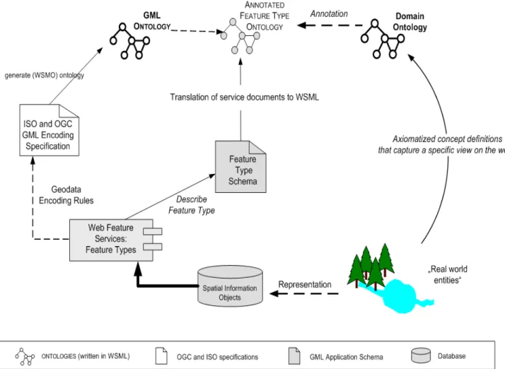
In order to capture the semantics of a data model, feature types need to be annotated (Klien, 2008). This can be done by mapping elements of the feature type schema to concepts in domain ontologies (Andrei, Berre et al. 2008). It is assumed that all members of the geographic information community will interpret the terminology used in their domain ontology in the same way and, at the
same time, people from outside the community are able to explore the intended meaning with the
help of the concept definitions (Roman, Klien et al. 2006). Figure 2.1 presents the concept of annotation between the domain ontology and the feature type ontology developed from the spatial
information objects. The process initiates with the real world entities, which are represented as spatial
information objects. These objects are encoded as features in the Geographic Markup Language
(GML) (Listings 2005) and served via OGC (Open Geospatial Consortium) data services to GML ontology. Theses annotated feature type ontologies may contain one or more feature types in the
same ontology.
This shall be achieved by annotating web content with consensual formalizations of the
knowledge published, often referred to as ontologies. (Feier etal.). Semantically enhanced information processing along with logical inference eventually shall allow the development of high quality
techniques for automated discovery, composition, and execution of Services on the Web, stepping
towards accurate integration of data on the Spatial Data Infrastructure (Stollberg et. al, 2004).
Figure 2.1: Overview of items involved in the process of annotating ontologies in the context of
WSMX (Schade, 2008; modified)
Mapping processes discussed earlier between schemas, focused on rather a syntactical
approach. Tools such as FME or Spatial Data Integrator are used to successively map different
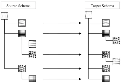
attributes of two different schemas to each other. Figure 2.2(a) shows an example, mapping the syntactical elements of a source Schema to a Target schema, using line diagram, where as Figure 2.2(b) shows how the mapping is really done using, FME. Two data model schemas are presented along with its attributes. The boxes represent the different attributes while the design filled in the
boxes represents different attribute types. As shown in the figures, in a schema mapping procedure,
Figure 2.2(a): Syntactical Mapping using conventional schema mapping tools.
Figure 2.2(b): Syntactical Mapping using conventional Feature Manipulation Engine (FME).
3 INTRODUCTION TO THE OBSM tool
This section will describe the tool from the background of the tool to the internal functionality
using the OBSM components, their arrangement within the tool and its functioning in greater detail.
3.1 Introduction to the General Scenario
The GUI is designed as a component in the Schema mapping architecture proposed for a
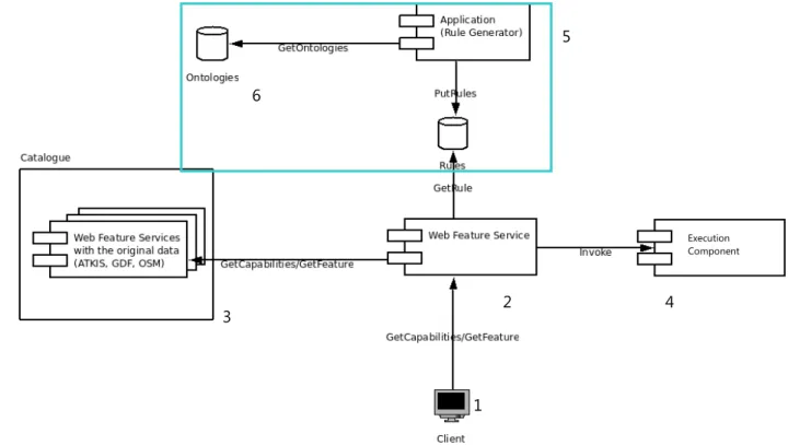
project at the Institute for Geoinformatics (IFGI) in Münster, Germany (Beckmann, et. al, 2009). The proposed architecture is presented in the Figure 3.1. Accordingly interaction between the components of the architecture can be described as follows; when the client (Figure 3.1) [1] has a requirement for a certain road data set, he request from the WFS [2], via a GetFeature(2) request. Then an OGC catalogue [3] is requested for available sources, then the central service checks for available
rules, and then those are processed in a translation.
IF the data is already available GetFeature request is sent to the WFS and the successful
response for the request is completed. If the required data is not available within the system, the
GetCapabilites(3) request is sent to the WFS including the original street data, which will then send the URL of the feature to the WFS, in order to look for the corresponding rules for the transformation. If
the required set of rules is available within the rules repository, WFS get the rules identified by the
feature type name, which is the index for the database. If the rules are not available for the schema
translation, rules will be defined accordingly within the rule generating component of the tool [5],
using the feature type ontologies [6]. This will then be taken back to the WPS, on the specified file
format of the Mapping file, which can really execute rules on the execution environment [4]. Once the set of rules are available within the WPS, it sends the Feature-URL along with the rules to the
execution component. Execution component performs the actual transformation, on the data gained
through the WFS, using the Mapping file. Server then uploads the data and sends the name
identifying the feature type to WPS. Subsequently, WPS-Server sends Feature-Identifier to client
where the client can download the data from the WFS.
( 2 ). “GetFeature” is one of the most prominent OGC standards is the Web Feature Service (WFS) Implementation
Specification (OGC, 2005b), an interface definition for the provision of vector data(OGC, 2005
(3 ). The service model is the overall model governing the structure of OGC Web Services. It is an architecture in
Figure 3.1: Components and the workflow of the architecture (Beckmann, et. al, 2009).
3.2 Scope of the tool
The facts mentioned in the section 1.2 prove that faster and less labor-intensive approach
is required for schema mapping. The most important applications for schema mapping GUIs are
virtual data model integration and data model translation, which define mappings at concept level
that can later be used at the data level when required.
The Figure 3.2 is a detailed explanation of the component presented in the Figure 3.1 by the highlighted blue box that exhibits the Communication of the GUI with external resource components.
As mentioned in the sub-section 3.1, second case on the WFS (to get the rules when required set of
rules are of available in the repository), is the main scope of the tool. As mentioned in the Figure 2.1, the GML ontology is directly developed from the feature type data model, which becomes the input
for the OBSM. This is linked with the feature type ontology and annotated with the domain ontology. This annotated feature type ontology is the input for OBSM.
When the requested set of rules is not available in the rules repository the GUI request the
source and target feature type ontologies. For both source and target, this annotated feature type
ontology is required in order to render the ontology in the tool. Within the tool the user can either
define new mapping rules in order to translate from source to target feature types or retrieve a set of
rules available for translation of two feature types. Once the set of rules are defined, the tool
develops the mapping file. The mapping file contains abstracted rules on its internal format. This will
Execution Component
1
2 4
3
5
then be converted to the mapping file format, which is required by the execution component within
the system architecture. It is then sent via WFS to the execution component, where the actual data
transformation is performed.
Figure 3.2: Communication of the tool with external resource components
3.3 Activity diagram
“An activity diagram represents the state of the method execution. i.e. the state of the object
executing the method; the activities in the diagram represent activities of the object that performs
the method” (Rumbaugh, Jacobson et al. 1996). Figure 3.3 presents the activity flow for the tool. The Activity diagram for the schema mapping use case depicts the steps involved in this workflow, which
can be described as follows;
As first activity, the user needs to select the FTO according to his source data model.
Concerning the steps present in the GUI, section of source feature type presents the step 01 while the
left hand branch presents the step 02. Right hand branch presents the step 03 where as saving and
exporting presents the step 04 of the GUI.
When the user selected the source feature type, user has two options:
Option 01(Left Branch): User can get a set of rules for the data model translation, which is already available from the tool. In this option the user first checks for available target feature types. If it is
available he can select the desired target and import the rules for transformation and save them at a Source FTO
(SFTO)
Source Data
Target FTO (TFTO)
OBSMTOOL
SFTO
Rule TFTO Execution
Component
Mapping File
Ontology
desired location as an OBSM mapper file. If it is not available he can go to the option 02, which means that the user defines new set of rules for data model transformation.
Option 02(Right Branch): User can define new set of rules at this option. User has to load the target feature type ontology. After source and target ontologies are rendered, the user can define new
mapping rules. A defined mapping record is accepted after the inference check, on the concepts and
the attribute of the concept. This process can be performed iteratively along with an inference check
until all the rules are defined. These sets of defined rules are then converted into a set of abstracted
rules by exporting to an OBSM mapper file, which can save into a desired location.
The activity diagram shows the steps where each action belongs, which makes easy to
understand the processes described in section 3.4.
Figure 3.3: Activity Diagram of OBSM
Step
Step Step
3.4 Operation of the tool
The operation procedure of the tool is completed in four steps. The four tabs found in the
GUI frame, indicate the steps that guides the user to complete a rule definition cycle. Figure 3.4
presents the opening screen of the tool
Figure 3.4: Opening screen of the tool
Step 01
Figure 3.5 presents the first step of the process, which describes the source data model. In this step the user is asked to locate the file containing the source feature type ontology. Once the
‘Locate Source FT’ button is clicked, a file chooser appearing on a pop-up window will allow the user
to locate the file.
Next operation in the step one is, to get a list of feature types. Once the ‘Extract’ button is
clicked the GUI parse the selected file and read through to get a list of available feature types. For
example, the GUI testing is performed with feature type ontologies built using WSML. The ontologies
Figure 3.5: First step of the process
Step 02
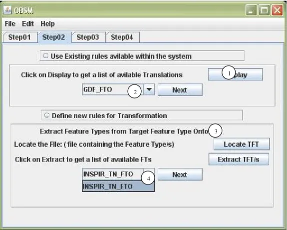
The step 02 gives the next phase of the process which is presented by Figure 3.6(a) and
Figure 3.6(b) respectively. In this phase the user is given opportunity to initiate the two alternative options; either user can decide to retrieve rules from the existing repository (Option 01) or define
new rules for the translation (Option 02).
Figure 3.6(a): First option in the second step of the process
( 4 )
Geographic Data Files (GDF) (ISO 2004)
( 5 )
Open Street Map (OSM 2008) (4)
Once the user selected the source feature type ontology (result of Step 01), the system
searches through the table in the rule repository, which act as the registry index for the translations
available in the local repository, to identify the mappings available and display the list accordingly,
Option 01: The user can browse through the rules repository and acquire a set of rules
available within the system (Figure 3.6(a)). By clicking the “Display” button (1), user can get a list of target feature types, in the combo box (2).
Option 02 (Figure 3.6(b)): The user is given opportunity to proceed with defining the rules for schema translation. Thus to start with, the user needs to load the target FTO to the GUI. This is done
similar to step 01, once the location of the feature type ontology file is entered by using the “Locate
TFT” button (3), the system parse the file and read through, to a get list of GML Features available in
the file. Once the user selects the desired target from a list (4) the system gets the desired GML
feature type ontology and saves a copy of the file in the Ontology directory in the OBSM ontology repository.
Figure 3.6(b): Second option in the second step of the process 1
2
3
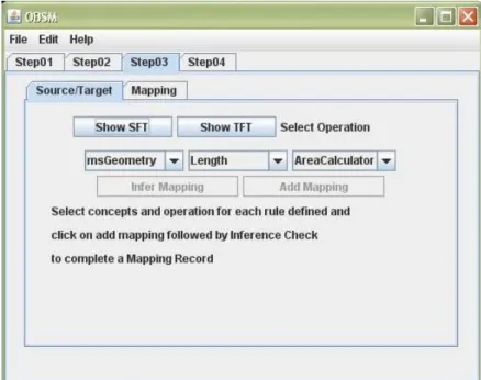
Step 03
Step 03 represents the Mapping component of the tool. General arrangements of the
graphical elements supporting this phase are presented in the Figure 3.7(a).
Figure 3.7(a): Arrangement of the objects in the third step of the process
This screen allows the user to visualize the ontologies graphically and define mapping rules.
Clicking ‘Show SFT’ or ‘Show TFT’ buttons render the source and target feature type ontologies in
separate pop up screens, as presented in Figure 3.7(a). This allows the user to browse through the ontology concepts and relations. Two separate buttons assigned for the purpose of rendering source
and target ontologies as it will provide the user, an easy observation panel for viewing the ontologies.
The structure is accompanied with dynamical rotating effect, in order to give a representation closer
to ontology development environment. Once a concept is selected, related concepts are highlighted
in red color, in order to express the relation with other concepts within the ontology. This graphical
representation of the concept maps is exhibited in the Figure 3.7(b). ‘Shuffle’ button rearranges the concepts in the rendering environment to refresh the rendering view. The assignment of an individual
concept to another is referred to as a “Mapping Record”. The appropriateness of the mapping record
could be assessed, using the “Infer Mapping” button.
By default “Infer mapping” and “Add mapping” buttons are disabled. First the user has to
decide the source and target concepts for a mapping rule using the concept maps. Then these
concepts need to be selected using the corresponding combo boxes present right below the
data type) is made available in the next combo box, where the user can define the mapping
operation.
Figure 3.7(b): Rendering view of the ontology by the GUI
Once options are selected for all four combo boxes, “Infer Mapping” button gets activated
allowing the user to check whether the mapping is acceptable. This will indicate that the operations
defined are compatible and can be implemented on the data types identified. After checking the
consistency, the mapping can be added to the table, using the ’Add mapping’ Button, one record at a
time. Definition of source and target concepts and the translation operation and checking the validity
of the mapping using ‘Infer mapping’ will complete a single mapping record.
After the definition of a single record these three fields (source concept, target concept and
operation) parse the parameter to a table, which is visualized within the ‘Mapping’ tab which will
define the mapping records as mentioned in the section 3.4 in the text. User can regularly refer to
the ‘Mapping’ tab and explore the previously defined mapping records. This is presented in the
Figure 3.7(c): Second phase in the third step of the process
If the user wants to remove a mapping record, which is already defined, he has to select the
record in the table and has to click on ‘Clear Mapping’.
Once definition of rules is completed, the user can generate the OBSM Mapping file by clicking on the ‘Generate Mapping’ button. After obtaining, the screen indicating the mapping file is
generated successfully; user can proceed to the next step. At the current development stage the tool
develops the mapping file, which is executable in the FME workbench.
The structure of the mapping record is given in Figure 3.7(d). Explanation of the OBSM mapping file
The mapping record is an example of translating attribute of an ATKIS feature type to an INSPIRE
feature type. It consists of the following:
Line 1-5: Defining the attributes of the ATKIS feature type. ‘msGeometry’, ‘NAM’, ‘WDM’, and
‘BRV’ are the attributes and ‘gml_geometry’, ‘char(50)’, and ‘number(10, 2)’ are corresponding
types.
Line 11- 15: Assigning an operation to a source attribute, ‘msGemetry’ in this case.
‘FACTORY_NAME’ refers to the operation assigned to the source attribute. ‘LengthCalculator’ is
the operation assigned to the source attribute in the example.
Line 17.22: Assigning the output of the transformation to the target attribute. In the example, the
Line 28-31: Defining the attributes of the INSPIRE feature type. ‘msGeometry’, ‘WIDTH’, and
‘LENGTH’ are the attributes and ‘gml_geometry’, ‘number(10, 2)’, and ‘number(10, 2)’ are the
corresponding types.
Figure 3.7(d) presents the structure of the sample ‘OBSM Mapping file’
Step 04
This step gives the user the opportunity to save a copy of OBSM mapper file, which can then be executed in the FME workbench. By clicking on the ‘Location’ button, the location can be selected
to save the file. ‘Export Mapping’ will export the file to the desired location, securing a copy in the
rules repository (Figure 4.8).
****************************** 1.GML_ATKIS_1_DEF FeatureA\
2.msGeomerty gml_geometry \ 3.NAM char(50) \ 4.WDM char(50) \ 5.BRV number(10,2) \ ...
11.FACTORY_DEF * TeeFactory\ 12.FACTORY_NAME LengthCalculator \
13.INPUT FEATURE_TYPE FeatureA_msGeometry \ 14.OUTPUT FEATURE_TYPE LengthCalculator_OUTPUT \ 15. _length @Length(10,2) \
16.
17.FACTORY_DEF * TeeFactory \
18. FACTORY_NAME "LengthCalculator_OUTPUT -> FeatureB Correlator" \ 19. INPUT FEATURE_TYPE LengthCalculator_OUTPUT \
20.OUTPUT FEATURE_TYPE __GO_TO_FINAL_OUTPUT_ROUTER__\ 21. @Transform(FME_GENERIC,SHAPE) \
22. @CopyAttributes(LENGTH,_length) \
...
28.GML_INSPIRE_1_DEF FeatureB \
3.5 Components of the Tool
The GUI interaction comprises four components. These are introduced in the following.
OBSM Mapping Component
The mapping component is the main element of the GUI. Here, mappings are defined from
source ontology to the target ontology, which is referred to as “A Rule Set”. Feature type ontologies
for the Mapping interface are retrieved from the internal repository, along with the annotations. One
mapping will result a set of rules (intermediate mapping file) which will then delivered to the system
architecture to covert to the format of the translator which performs actual transformation. For
example; If the FME should be used for translation, an FME Mapping file is exported, if translation
should be executed in GeoXSLT, a corresponding file is created. The mappings are defined manually
between the concepts of the ontology. This step actually implements main idea of the thesis. The
concepts of the domain ontology annotated with the actual data model, make use of the semantics
in order to make the process of defining the mapping easier.
The definition of a mapping record is supported by a GUI, which allows;
○ Searching and panning through source and target ontology concept maps allow understanding the concepts and their relations in the considered data models.
○ Assignment of source ontology concepts to the target ontology using the combo boxes in the main window.
○ Definition of the type of operator for the translation; The system identifies the type of the attribute corresponding to a concept and makes available only a selected set of operators for
each mapping. For example;
Schema translation between data models ATKIS and INSPIRE:
Table 3.1 presents the Schematic representation of the rules definition table. Source and
Target presents the source (ATKIS) and target (INSPIRE) concepts. The operator define the operation
needs to be performed on the data translation.
Source Target Operator
msGeometry LENGTH LengthCalculator
Table 3.1: Schematic representation of the rules definition table
BRV attribute can be mapped to the LENGTH, because the type is same. Yet the operator
OBSM Ontology Repository
This component serves as a database for the ontologies used within the tool. The tool comes
along with a separate directory called “Ontology.dir”. Once the user locate the file containing the
source feature type ontology file in step 01-section 3.3, a copy of a file will be automatically copied to
the repository, User can use these files any time for generating mapping files.
OBSM Rule Repository
The Rules Repository consists of a directory (RulesRepository.dir) and ‘Rule Repository
look-up table’. The Rules Repository look-look-up table consists of following parts;
- Feature type name of the GML feature type of Source feature type
- Feature type name of the GML feature type of Target feature type
The system has a directory which contains mapping files for standardized data models which
are stable and not subject to frequent changes, schema mappings (“Rule sets”) which are ready to use
which comes along with the tool. In addition each time when a mapping file is exported, a copy is
saved in the directory.
OBSM Mapping File Generator
The OBSM rule generator generates OBSM mapping files, out of the rules, which have been stored in the ‘Mapping Table’.
The structure of a mapping rule consists, of:
-Attribute of the source data model
-Corresponding attribute of the target data model
-Type of the each attribute following the format declaration of execution environment
-Identifier for the transformation
(For example; In case of using the FME, an FME specific identifier is generated)
The translation operation can be selected using the combo box in the step 03 presented in
the section 3.3. Once the parameters (i.e. Source and target concept considered in each mapping and
the translation operation) are set these will be added to the rule table. The set of rules will be resulted
in an OBSM mapping file (intermediate file), which can then be translated to the standard format of the FME mapping file before submitting to the WFS.
The user interface is developed using JDK6, development environment, along with the
“wsmo4j” library for java. The order of occurrence of the operations described above is explained in
3.6 Sequence diagram
Sequence diagrams (Rumbaugh, Jacobson et al. 1996) are one means for describing the internal workings of software components. The interplay of the tool components is shown in Figure 3.9. The sequence diagram for the schema mapping use case depicts the two options involved in this workflow, which can be described as follows. . “alt” presents the two different alternative paths present in the GUI operation, in obtaining an OBSM mapper file and “seq” presents the different components present within the tool.
Alternative 01: Request rules from Rules Repository
User can get a set of rules for the data model translation which is already available with in the
rule repository, using [RequestRulesfromRapository]. In this option GUI send [GetOntology:OntoID]
request to the ‘OntologyRepository’ to get the source Ontology as a WSML file [GetSOntology]. Next
[GetSFTO] is send to the ‘FeatureTypeOntology’ and available feature types are taken using
[GetSFTResponse:FTO]. Next, a list of targets is taken for the selected source feature type, using the
[RequestList:FT_Name] from the ‘RulesRepository’ using the response [RequestListResponse]. Once
the user decides the preferred target, the OBSM mapper file can be taken using the [GetMapperFile] request and save in a desired location.
Alternative 02: Define new Rules
User can define new set of rules at the option [Define New Set of Rules]. User sends the
[GetSOntology: OntoID] request to the ‘OntologyRepository’ and loads the source and target
Ontologies using [GetSOntology]. This request is sent to the ‘OntologyRepository’ when both source
and target ontology is retrieved. The desired source feature type is loaded via [GetSFTO] request and
[GetSFTResponse:FTO] response. The desired target feature type is loaded via [GetTFTO] request and
[GetTFTResponse:FTO] response to the ‘Feature Type Ontology’.
Then FTOs are requested to render into concept maps via [RenderSource] and [RenderTarget(wsml)]
requests and [GetSConceptMap], [GetTConceptMap] responses respectively to the ‘Mapping
component’. Rules are defined for each attribute type using [DefineOperation(InpurAtt)] request and
[GetOperation] response to the ‘Operation Repository’. Next the set of defined rules is taken in to a
OBSM mapper file by sending [GetListOfRules:MapperFile] request to the ‘RuleGenerator’ and [GetListOfRulesResponse:Mapper File] response; via the [GetMapperFile] request user can get the file,
save in a desired location while [Save(MapperFile)] request secures a copy of the mapper file in the
Figure 3.9: Sequence Diagram of OBSM
3.7 Evaluation of the tool
Usability of a product is a function of the particular user or class of users being studied, the
task they perform, and environment in which they work (Bevan, Kirakowski et al. 1991). Usability of an interface is one of the most important features that impacts on the performance of that system, when
Systematic user acceptance testing with actual users is an important fact for the development of
user-friendly interfaces. Usability testing approaches has gained a wider range of inputs from
usability engineering studies (Whiteside et at., 1988; Nielsen and Mack, 1994) and the more general work on designing usable artifacts (Norman, 1986; Landauer, 1995). The framework for the development of a user interface evaluation can be developed by adopting various procedures
including the open process framework (Firesmith and Henderson-Sellers, 2001), the user action framework (Andre et al., 2000) or the heuristic evaluation method (Nielsen, 1994).
The evaluation performed on the GUI considered five main factors identified for usability evaluation
(Nielsen and Molich 1990): Namely;
○ User satisfaction;
○ Ease of learning;
○ Ease of use;
○ Error prevention; and
○ Efficiency of the interface.
Heuristic evaluation is an informal method of usability analysis where a number of evaluators
are presented with an interface design and asked to comment on it.(Nielsen and Molich 1990).
The questionnaire consists of two sections. Section 01 of the questionnaire dealt with users’
preferences whereas the Section 02 dealt with the general performance of the system. The questions;
1.1-1.10 identifies the users attitude and perception on the tool where as questions 2.1 -2.5 identifies
the strengths and weaknesses of the GUI. The open text question is designed on the objective of
finding the recommendations for the improvement of the GUI. In addition, the users were also asked
to comment on their overall impression of the tool such as the most and the least liked features,
problems encountered, and some advanced useful features that could be incorporated into the tool.
The reason for selecting the heuristic evaluation is that it can be implemented quickly and
conveniently through experienced pool of evaluators.
The evaluation was performed while developing the tool, having three main objectives;
○ To discover users’ attitudes and perceptions on the tool
○ To assess the strengths and weaknesses of the tool and
○ To provide a set of recommendations for improvement.
The tool was evaluated using prototype model and questionnaire [as shown in the Appendix
(a)] with the students in the schema mapping course (Sample size 10), who are a group of
Results from the questionnaire
According to the results of the evaluation on the usability of the GUI, following justifications
can be made on the general handling of the system. The number of responses for each acceptance
level is converted to the fraction of the total population for the convenience of comparison.
Higher percentages of positive responses were obtained for questions 1.1, 1.3, 1.5, 1.7 and 1.9. This
implies that the user is satisfied with the system’s general capabilities and is in a position to employ
the tool frequently in schema mapping procedures. The layout and the integration of the
functionalities and the capabilities seem to be arranged in a coherent manner that the most of the
users prefer the flow of work. In addition, users found the GUI as promising for easy understanding in
its operation and confident on using the GUI. As the concepts and the logic of operation identified in
the steps are rather familiar for the users in getting the desired output.
Questions 1.2, 1.4, 1.6, 1.8 and 1.10 have obtained a lower percentage of acceptances,
implying that complications and unnecessary confusions of operations within the system are
minimized. In addition most of the users are satisfied with the consistency of the tool is up to the
standard and is really aids the user by not requiring the user to read piles of documents before using
the system.
The results of the section 01, is presented in the Table 3.2
Section 01:
Strongly
Disagree Disagree Neutral Agree
Strongly
Agree
% % % % %
1.1. I think that I would like to use this system frequently 11 0 11 44 33
1.2. I found the screens unnecessarily complex 22 78 0 0 0
1.3. I thought the layout was easy to use 0 0 56 22 22
1.4. I think that I would need the support of a technical person to
be able to use this system 56 33 11 0 0
1.5. I found the various functions in this system were well
integrated 0 11 33 44 0
1.6. I thought there was too much inconsistency in this system 44 33 22 0 0
1.7. I would imagine that most people would learn to use this
system very quickly 0 0 0 44 56
1.8. I found the system very cumbersome to use 22 44 33 0 0
1.9. I felt very confident using the system 0 0 11 78 11
1.10. I needed to learn a lot of things before I could get going with
this system 33 22 11 22 11
The results of the section 02, is presented in the Table 3.3
Section 02:
Very
Bad Bad Satisfactory Good
Very
Good
% % % % %
2.1. How do you rate the general handling
of device – Ease of Operation 0 11 0 78 11
2.2. How do you rate the display – Visibility,
Data display on the screen 0 0 22 67 11
2.3. How do you rate the logic of operation
menu? 0 0 11 67 22
2.4. How do you rate the ease of information
provision 0 0 56 33 11
2.5. How do you find display scale of diagrams 0 22 33 22 11
Table 3.3: Results obtained for the section 02 of the questionnaire (Percentage of votes from the total
responses).
Questions 2.1, 2.2, 2.3 and 2.4 have obtained a higher level of acceptance implying that the user
is satisfied with the general functioning and operation. In addition, the user is satisfied with general
logic of operation. Only the question 2.5 seems to have obtained lower level of acceptance from the
population compared to the other questions implying the, scale of display of the graphics need to be
4 APPLICATION OF THE TRANSLATION TOOL
Two data models are used in the evaluation of the OBSM mapping tool’s functionality. 1. ATKIS - "Authoritative Topographic - Cartographic Information System"
2. INSPIRE Data Specification on Transport Networks.
4.1 Data Models used in evaluation
4.1.1 ATKIS -"Authoritative Topographic Cartographic Information System"
ATKIS data model is the result of a multistage research and development project of the
German State Survey Working Committee (AdV) in the fields of state survey, cartography and
automation. The Survey Authorities will use ATKIS to provide for the changing demands being made
on the state survey. A comprehensive summery of ATKIS is presented in a report, based on a
translation (Hesse and Leahy 1990) of official AdV documents (AdV 1988, "Gelbes Heft"). Detailed descriptions are available in separate documents (AdV Arbeitsgruppe ATKIS 1989). ATKIS comprises a nationwide standardized digital topographic database with a three dimensional structure. The
database is built in the public interest and transferred to public and private users as a state service.
The database is authentic and current. ATKIS is based on a modern cartographic model theory, as
shown in Figure 4.1. The real world with its topographic objects and its thematic structure is presented as the original. The topographic survey creates the primary model, a topographic
landscape model. This model is transformed through cartographic work into a secondary model, the
cartographic landscape model. During both these stages generalization processes at various levels
take place resulting in different degrees of detail. A tertiary model is built by adding user specific
original data models or other derived models.
The creation of the primary model of the landscape takes place in the form of a three
dimensional survey, based on topographic objects and object parts and their relationships. The
objects are captured by shape, position and their topological relationship. Attributes are also
assigned, coded and stored. Through this process of topographic modelling, a digital topographic
landscape model is created in ATKIS terms, a Digital Landscape Model (DLM). Depending on the data
capture accuracy and degree of structure, DLM will differ in degree of information density.
The creation of a secondary model is based on the DLM as the primary model. The stored
topographic objects are assigned with symbology according to cartographic generalization rules.
Through this process of cartographic modelling, a digital cartographic landscape model is created in
ATKIS terms, a Digital Cartographic Model (DKM) according to the specifications of ‘ATKIS3100’
(Specification on road transport). Depending on the symbology catalogue and its degree of
generalization chosen, a number of DKM versions for any map scale can be produced.
4.1.2 INSPIRE Data Specification on Transport Networks
INSPIRE data model specification (2008b), includes four application schemas for Road, Rail,
Water and Air transport networks based on the common transport network elements defined in the Common Transport Elements application schema. Includes links between different networks. Also
includes the trans-European transport network as defined in Decision 1692/96/EC of the European
Parliament and of the Council of 23 July 1996 on Community guidelines for the development of the
Trans-European transport network and future revisions of that Decision”, according to the D2.8.I.7
Data Specification on Transport networks. Transportation networks is one of the themes found in the INSPIRE directive (2007/2/EC, 2007) for spatial data Infrastructure themes. The Common Transport Elements covers elements that are shared by sub-themes Road, Rail, Water and Air transport networks
and defines a number of common properties of transport network elements (INSPIRE, 2008a).
Sub themes can be used in integration with other spatial data themes in an integrative
approach of developing transportation networks. In addition these sub themes are important since
they make the explicit background for topographic representations, link and node networks,
inter-theme connectivity and capability to reference associated information. Thus this approach provides a
framework for users to configure and associate their own information (from surface condition
surveys, to journey planning, to Trans-European transport policy making etc.) using existing transport
networks information in each Member State. (INSPIRE, 2008c)
The INSPIRE data model specification (2008b), defines, a liner network as the linear network is handled as a network of connected linear elements (links) with points (nodes) at the ends of the lines
function in a network may be represented in the dataset. (Figure 4.2) describes the relationship of the data specification with supporting information architecture, which is explained in the sub chapter
above.
In addition the data model schema (2008a), describes three fold primary aspects;
○ Spatial (geometric representation as point, line and surface) are parts of the network;
○ Temporal (temporal validity – description of when the network element exists in the real world and also optional information on when data was entered, modified or deleted in the dataset) and
○ Thematic (related to the specialization of the sub-themes).
Figure 4.2: The relationship of the data specification with supporting information architecture (Source:
D2.8.I.7 Data Specification on Transport networks)
All sub-themes (Road, Rail, Water, Air) employ a link and node structure to represent the content in the form of a linear network with the following sub-theme specific characteristics in relation to
road transportation: (INSPIRE, 2008a):
○ A road system used for the transportation of vehicles in the Road transport networks;
○ Ownership and traffic direction in the Road transport networks, 4.2 Annotation of the feature types to the domain ontology
color. The attributes of ATKIS data model and INSPIRE data model are represented in green and blue
color respectively. In the process of annotation, data model attributes and domain ontology concepts
are matched and linked. For example In the ATKIS data model ‘BRV’ is the attribute representing the
width of the road. Therefore BRV is annotated with the domain ontology concept ‘Road’.
Figure 4.3: Annotated feature type ontology
The description of the Domain ontology
In the considered extraction from the ontology, Traffic elements are a part of the traffic
infrastructure. Carriage ways and roads are part of the road way, which is a specific traffic element.
4.3 Use of data in the tool and results obtained
Application of OBSM
This chapter explains the application of real data on the GUI. This stage of development, the
tool is designed to use the FME workbench as a platform to execute the rules and WSML as the
ontology developing language.
Step 01
In this step the source feature type is loaded to the system.
Procedure;
○ Click on the “Locate Source Feature Type Ontology” button. (Figure 4.4(a))
○ Locate the file using the file chooser window appearing
The file chooser allows only single file selection in this version of the tool. Once the file is selected it
will be send through a passer and read in order to extract the feature type name. The file chooser
only allows selecting .wsml files as the source ontology file.
Figure 4.4(a): Selecting the source feature type ontology file
Procedure;
○ Click on the “ Extract SFT/s” button (Figure 4.4(b))
Once the “Extract SFT/s” is pressed, a list of feature types available in the file is displayed as a
list in the combo box. The user can select only one feature type for mapping at this stage of
development.
Figure 4.4(b): Extracting the source feature types
Step 02
In this step the user is given the opportunity to trigger the one of the alternatives present in
the system in order to generate the rules file.
Procedure;
Alternative 01: Radio button 01
User can check whether there is a set of rules already defined is available in the rules
repository by clicking on the ‘Display’ button. (Figure 4.5(a))
If this option is selected; the step 3 will not be activated. User can directly proceed to the step 04 by
clicking on the ´Next´ Button.
Alternative 02: Radio button 02
User can define new set of rules for the schema translation.
○ Click on the “Locate TFT” button. (Figure 4.5(b))
○ Locate the file using the file chooser window appearing
The file chooser allows only single file selection in this version of the tool. (Figure 4.5(b)). Once the file is selected it will be send through a passer and read in order to extract the feature type
name. The file chooser only allows selecting .wsml files as the source ontology file. Once click on the ‘Extract TFT/s’ the user can extract the target feature type (Figure 4.2(c)).
Figure 4.5(c): Extracting the source feature types - alternative 02
Step 03
If the user decides to proceed with the second alternative; the step 03 tab will be activated. In
the Source/Target tab user can click on the ‘Show SFT’ and ‘Show TFT’ to render the concept maps of
source and target feature types (Figure 4.6(a)). Concurrent rendering of both target and source feature types will make the panning and navigating through the concepts easier. Selections of the
source and target concepts will create the entries in the table, which can be viewed and manipulated
using the table. Selected source and the Target concepts and the type will be displayed initially in the
table. Once the three entries are selected, ‘Infer Mapping’ will be activated. If the mapping record is
validated by the system, as correct, ‘Add Mapping’ will be activated. Then the record will be displayed
in the table of the ‘Mapping’ tab. Records can be removed from the system, when needed using the
‘Clear Mapping’. User can select the operation to be manipulated on the attribute data, made
available according to the type. (Figure 4.6(b))
Figure 4.6(a): Rendering and navigation trough concept maps
Figure 4.6(c): Generation of the OBSM mapping file
Step 04
In this step the user can save a copy of OBSM mapper file, which can then be executed in the FME workbench. By clicking on the ‘Location’ button, the location can be selected to save the file.
‘Export Mapping’ will export the file to the desired location, securing a copy in the rules repository
(Figure 4.7).
5 CONCLUSIONS AND FUTURE WORK
Key strengths of the tool are identified as the attractive user interface and the ability to interact in
an easy to understand language compared to the factors that contribute to its overall user
acceptance are its adoption of consistency in terms of conventions used, screen layouts, minimum
use of colors, and use of graphics and icons.
It transpired from this study that users prefer an attractive graphical user interface in the
process of schema mapping. In addition, the tool is attributed with simplified icons and visible screen
instructions to enhance the overall performance. The system provides a feedback of an acceptable
level and frequency though it is inadequate. Also the feedback emphasized on the necessity to
include search tips, FAQ, and an online search guides to improve the user friendly features of the
tool. The evaluation has resulted in bringing in to limelight several important developmental areas.
The following could be addressed in the future upgraded versions of the tool:
○ Provision of additional online help documentation along with examples.
○ Ensuring that the content is kept relevant through regular content updates via Web Services with a public accessible repository for rules and ontologies.
○ Improving error-handling messages through enhanced functionalities that provide
suggestions and examples of problem resolutions.
○ Addition of basic navigational buttons and functions (such as “next”, “previous”, “return” and “undo” buttons) to navigate within the 3rd tab (In the table).
○ Provisions to be made in the system to access directly through the Internet in addition to the current local system.
OBSM only supports and confines to the transformation of single feature type at a time. But there may be instances where the user needs to combine several concepts from different feature
types simultaneously. This opens up new vistas for future development and expansion of this study.
In addition the mapping only allow 1:1 mappings, meaning the assignment of operations on a
concept can generate rules to translate one concept to another but two or more concepts can not be
considered in resulting a single concept. This requires attention because in reality, several concepts
contribute to define another concept frequently. The set of rules defined earlier are stored in a single
(local) repository. But if this could be stored in a shared environment like Web Services, sharing of the
rules could be done more comprehensively. Since the tool is mainly built on the SWING project
context, it only supports .wsml file format for ontology input and reading. But in reality ontologies are
written in several different languages which support several different formats.
While developing the rules file, system recall the corresponding data model attribute in the