Designing of CK45 Carbon Steel and AISI 304 Stainless Steel Dissimilar Welds
Hesam Pouraliakbara,b*, Mohsen Hamedia, Amir Hossein Kokabia, Ali Nazarib
aDepartment of Materials Science and Engineering, Sharif University of Technology, Tehran, Iran bDepartment of Advanced Materials, WorldTech Scientific Research Center (WT-SRC), Tehran, Iran
Received: December 23, 2012; Revised: September 2, 2013
Gas tungsten arc welding of CK45 and AISI304 stainless steel was performed through preparation of different types of samples using ER308L and ERNi-1 wires. Welded samples were studied by different techniques including optical metallography, scanning electron microscopy equipped with energy dispersive X-ray spectroscopy (SEM-EDS), X-ray diffraction, hardness measurements and impact test. It was observed that in the buttered specimen, the structure of the weld metal was completely austenitic while the microstructure of unbuttered sample was duplex ferritic-austenitic. M23C6-type carbides were observed within the weld metal of both as-weld specimen types. Effects of different post-weld heat treatments (PWHTs) were investigated. The experimented results concluded that simultaneous grain growth and carbides precipitation were competitive during PWHT. Also, there were not any indication related to sigma-phase in as-welded and PWHTed specimens due to their lower Cr/Ni ratios and insuficient preservation times.
Keywords: dissimilar weld, microstructure, mechanical properties, PWHT
1. Introduction
According to the fact that every part of a process system operates at a speciic condition, different structural alloys such as stainless steels, low-alloy and carbon steels due to their special properties are used in the design; resultant in dissimilar metal welded joints1,2. Joints of dissimilar
metal combinations are employed in different applications requiring certain special combination of properties as well as to save cost3,4. Final properties of dissimilar joints depend on the base materials, iller metals, microstructural evolutions in fusion zone, and utilized welding technique5-7.
Conventional welding of many such dissimilar metal combinations is not feasible owing to the different metallurgical problems. On the other hand, dissimilar metal welding of stainless steels to carbon or low alloy steels has a wide application in industry. These dissimilar metal joints are widely used in pressure vessels, boilers, heat exchangers of power generation industry and petrochemical plants and oil and gas industry; however, they have a number of challenges such as solidiication cracking, hydrogen cracking, and formation of brittle phases that may cause the failure of components before the expected design life8-11.
Carbon diffusion and subsequent formation of harmful carbides in the weld metal is considerable in joining of low alloy and carbon steels to stainless steels. Hence, decarburization and grain growth take place in heat affected zone (HAZ) of carbon steel affect the mechanical properties. At the same time, in the adjacent weld metal, carbides will be formed. Carbides will substantially increase the hardness
of weld and increase the likelihood of cracking in this zone. Moreover, carbon migration is considered to be a signiicant factor in determining the life cycle of a weld12,13.
Many key factors such as different physical and mechanical properties of base materials and probability of compounds and alloying in the weld zone must be considered while dissimilar welding; however, the importance of factors might be depend on the implemented welding technique. Based on literature, many attempts had been done in dissimilar metal joining by researchers through fusion and state welding. Among the solid-state techniques, diffusion welding, explosive welding, friction and friction stir welding are known as the most applied methods3,4. In the fusion category, beam-assisted
techniques and arc weldings are the most interested methods. Gas-tungsten arc welding (GTAW) is the most conventional fusion welding method for dissimilar joints since applies an inert medium for shielding and protecting the weld pool which is also used in this study. In an overview, GTAW can result in a high-quality, low-distorted, spatter free, both iller added and autogenously produced, dilution and heat transfer controlled welds, and could be applied for vast variety of metals such as carbon and stainless steels welds1,2,14. In this regard, selection of a suitable iller metal would be important in producing an appropriate dissimilar metal joint. Carbon steel to stainless steel welding practitioners usually select the iller metal such that the joint is considered as being stainless steel, rather than being carbon steel. Over-alloyed illers are used to avoid dilution of the alloying elements in the fusion zone of the parent stainless steel. Also, austenitic or
base iller metals are commonly used to join stainless steel to carbon and low alloy steel. The choice depends on the application as well as the service conditions2,5-7. Austenitic
steels have greater solubility for carbon when compared to ferritic steels. Therefore, carbon migration and resultant depletion in carbon or low alloy steel is substantial when an austenitic iller metal is used1.
Utilizing such a speciic joining technique would have its own dificulties and considerations. It is obvious that in solid-state welded joints due to lower probability of microstructural evolutions, problems relate to metals alloying is normally insigniicant since it is the major considered phenomenon in fusion methods1. The principals that are responsible for inal properties and specially failure of dissimilar arc welded joints are comprised of microstructural and detrimental phase evolutions, solubility incompatibility of base metals and applied iller metal, differing melting points, differing thermal properties such as expansion coeficients and conductivities, problems incorporating the elemental diffusion due to different service conditions of metals such as oxidation and corrosion; however more information in this regard could be found in literature1,2,14,15.
As a brief review, factors affecting weld integrity could be relate to weld metal, dilution, melting temperatures, thermal coeficients and thermal conductivities1,2. Also, welding technique, iller metal selection, joint design, buttering, pre- and post-weld heat treatments are constitute the most important considerations in dissimilar welding1.
In addition to carbon diffusion and its subsequent incorporating problems such as carbides formation in the fusion zone of low alloy and carbon steels to stainless steels joints, in some cases, the weld microstructure contains δ-ferrite and a subsequent transformation of δ-ferrite to austenite will occur. Since the diffusion rate in solid is much lower than that of in liquid, transformation of the entire ferrite is impossible and inally a small quantity of ferrite remains14,15. In addition, excessive heat input
in GTAW technique varies the cooling rate and therefore affects the amount of remaining δ-ferrite16. The predominant
precipitates found in weld metal exposed to temperatures of about 550 °C are M23C6- and MC-type carbides in unstabilized and stabilized steels, respectively14. Carbides
in weld metal can either form during welding or servicing and also during PWHT17-22. The process also tends to occur
more rapidly in weld metals incorporating δ-ferrite1,14,20. In fully austenitic welds, kinetics of sigma phase precipitation is very slow and usually requires extended times. In addition, ferrite is richer than austenite in chromium. Consequently, ferrite accelerates the sigma phase formation. In the other
words, ferrite bearing weld metals are susceptible to sigma embrittlement23.
Based on the works conducted in dissimilar welding of steels concerning different aspects, such as microstructure and mechanical properties investigations13,16,19,20 along with
studies on corrosion behavior24-28, it can be found that there is still too many objects need to be clariied and understood. Hence, in the present study, fusion welding of CK45 carbon steel and AISI304 stainless steel which targeted for using in power plant transition joints has been prepared applying GTAW technique. Two different types of samples with ER308L and ERNi-1 as iller and buttering wires were produced. PWHT was conducted in the range of 550-700 °C for 1-100 hours. Subsequently, samples were studied through metallography, SEM equipped by EDS, XRD, hardness measurements and impact tests.
2. Experimental Procedure
CK45 medium carbon steel and austenitic AISI304 stainless steel together with ERNi-1 and ER308L as buttering and filler wire, respectively were employed. Table 1 listed the chemical compositions of materials. The 250 × 60 × 8 mm specimens were prepared according to single-V groove joint design with 70° groove angle using 2 and 3 mm root face and root gap, respectively. Two different types of specimen were prepared. In type-A, layer of ERNi-1 was deposited on CK45 as a buttering layer with the minimum thickness of 4 mm. Then, ER308L wire was consumed to join the plates. In type-B, plates were joined using ER308L without any buttering. Totally three passes of GTAW were conducted in each type. Table 2 summarized the welding parameters.
In order to eliminate the heat sink effect, carbon steel plates were preheated at 200 °C. Final heat treatment of samples was done at 400 °C for about one hour followed by furnace cooling. During welding, interpass temperature was controlled to be in the range of 150-200 °C. In order to experience the effects of PWHT, samples were preserved at 550 °C and 700 °C for 1-100 hours and then were air-cooled. Marble’s modiied reagent (20gr CuSO4 + 50 mL H2SO4 + 100 mL HCl + 100 mL H2O) was used to etch stainless steel and weld metals. Nital’s reagent (10 mL HNO3 + 90 mL ethanol) was used to etch carbon steel. Electrolytic 10 wt% oxalic acid solution was applied to observe carbides using the voltage of 6V for 15-20 seconds. Rockwell B hardness measurements were performed on as-weld and PWHTed samples. X-ray diffraction pattern (XRD) was employed to investigate the precipitates. To study toughness and fracture resistance of weld metals and
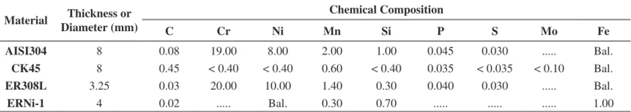
Table 1. Chemical analysis of the as-received base and iller metals.
Material Thickness or Diameter (mm)
Chemical Composition
C Cr Ni Mn Si P S Mo Fe
AISI304 8 0.08 19.00 8.00 2.00 1.00 0.045 0.030 ... Bal.
CK45 8 0.45 < 0.40 < 0.40 0.60 < 0.40 0.035 < 0.035 < 0.10 Bal.
ER308L 3.25 0.03 20.00 10.00 1.40 0.30 0.040 0.030 ... Bal.
HAZs, Charpy impact test employed since the samples were prepared according to ASTM E23[29]. Also, fractography by
means of SEM performed on impact specimens.
3. Results and Discussion
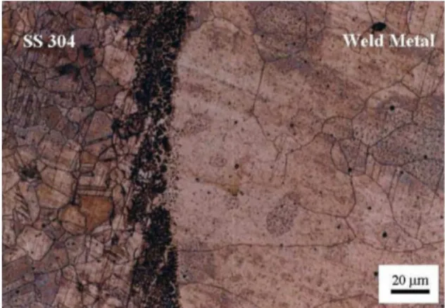
Metallographic investigations showed that the weld metal of type-A samples was completely austenitic (Figure 1) due to existence of Ni entering into the weld metal as an austenite-promoting element; however, weld metal in type-B samples had duplex ferritic-austenitic microstructure (Figure 2).
Chemical quantometric analyses of welds performed and compositions were listed in Table 3. Primary solidiication of austenitic steels can occur as either austenite or ferrite. At higher Cr/Ni ratios, primary solidiication occurs as δ-ferrite (FA solidiication type) while at lower ratios, it occurs as austenite (AF solidiication type)14. Figure 3 schematically illustrates the dependence of solidiication types with Cr/Ni ratios in austenitic steels in equilibrium condition. Based on literature, Fe content in weld metal in addition to Cr and Ni contents could have inluence on the range of solidiication and its dependence with composition; since, increase in Fe content in a constant Cr/Ni ratio get the concurrent existence region of ferrite and austenite narrower14,30. When an alloy solidiies as ferrite, it could be either fully ferritic or consisted of a mixture of ferrite and austenite at the end of solidiication path. Under equilibrium cooling condition, most or approximately entire of ferrite transforms to austenite and for the rapid cooling conditions, such experienced in welding, this transformation is suppressed and ferrite remains in the structure. According to chemical analyses (Table 3), the ratio of Cr/Ni = 2.00 in type-B sample comparing with Cr/Ni = 1.29 in type-A specimen is high enough to induce solidiication initiation with δ-ferrite following with transformation to austenite during rapid cooling. Transformation of austenite takes place through peritectic and eutectic reactions in solidiication. Buttering layer not only decreases the Cr/Ni ratio in the weld metal of type-A specimen due to increasing Ni concentration but also prevents carbon diffusion from carbon steel in spite of remarkable concentration gradient. Generally, decreasing the Cr/Ni ratio promotes austenite stability in the weld metal. Considering that carbon is less soluble in ferrite rather than austenite, increasing the Ni concentration in fusion zone facilitates the carbon migration, but deposited buttering layer acts as an augmentor agent of Ni in fusion zone and also by its stability during welding prevents carbon migration. Partial melting of Ni layer during welding simultaneously controls the dilution and plays as a barrier opposite to carbon which should diffuses through solid layer to reach weld
metal. It noteworthy to mention that diffusion in a solid takes much more time rather than through such a liquid/melt phase due to lower diffusion coeficient in solid.
Different ferrite morphologies (skeletal, lathy, acicular and Widmanstätten) could be formed in order to varying the diffusion-controlled reaction through ferrite-austenite interface14,31. Cooling speed, Fe content and Cr/Ni ratio
affect the ferrite morphology via changing the diffusion parameters30. Since the cooling speed was moderate as a
result of preheated and controlled interpass temperature as well as adequate Cr/Ni ratio in type-B specimen, δ-ferrite with skeletal morphology was formed in weld metal (Figure 2). SEM-EDX analysis was performed on black zones shown in Figure 2 while the spectrum and chemical results are displayed in Figure 4. Analysis result based on Ni and Cr contents proved ferrite existence.
The presence of δ-ferrite reduces the ductility and potentially the toughness. In addition, austenite/ferrite boundaries could be preferential sites for the precipitation Figure 1. Weld metal microstructure of type-A specimen.
Figure 2. Weld metal microstructure of type-B specimen. Table 2. Applied welding parameters.
Specimen Type Filler Metal Current
(A)
Voltage (V)
Polarity Arc Travel Speed (mm/sec)
A ERNi-1 110 13 DCEN 1.34
ER308L 120 13 DCEN 1.46
of M23C6-type carbides and sigma-phase of which the latter would be an embrittling agent in stainless steels32,33.
Figure 5, schematically illustrates the precipitation sequence of sigma-phase at various sites such as δ-ferrite islands. Sigma-phase (tetragonal Fe-Ni-Cr-Mo phase) and carbides may form in austenitic steels. Based on literature, sigma-phase, nominally FeCr, is hard and brittle and when presents in large volume fraction can reduce toughness and ductility remarkably1,32,34. In a fully austenitic microstructure, sigma
precipitations are relatively sluggish and normally need extended times and higher temperatures14. Its formation
range is 600-900 °C and it forms rapidly in ferrite/austenite interfaces32,34; hence, weld metals containing ferrite are
most susceptible to embrittlement. Higher Cr content not only results in higher amounts of carbides but also promotes sigma-phase formation1,14. X-ray diffraction was
employed to detect the sigma-phase formation, since the patterns showed that both as-weld samples were free of any indication related to sigma-phase. Samples of both types soaked in 550 and 700 °C for 1, 10 and 100 hours to investigate if PWHT could induce phase formation in these joints. Subsequently, similar to as-weld specimens, they had not any indication related to sigma-phase. As a result, the inexistence of sigma-phase might relate to inadequate conditions (Cr/Ni ratio) and/or might need more than 100 hours of preservation.
M23C6-type carbides, the most widely observed carbide type in austenitic stainless steels, strongly affect the corrosion resistance and precipitated very rapidly along grain boundaries in temperature range of 500-900 °C while the fastest rate of precipitation takes place in 650-700 °C[32,33]. The major compositional factor for carbides
formation is carbon content. According to Table 3, weld metal carbon content in both type-A and type-B specimens were high enough to cause immediate formation of carbides besides cooling at the range of 550-850 °C in which chromium has a great afinity for carbon. Based on microscopic investigations, carbides were detected within weld metal in both as-weld specimen types; however, higher carbides amount in type-B sample was detected Table 3. Chemical analysis of weld metals.
Specimen Type
Chemical Composition (%wt.)
Fe C Cr Ni Mn Si S P Mo
A 70.35 0.08 15.66 12.11 1.42 0.33 0.020 0.021 0.05
B 71.84 0.13 17.45 8.71 1.49 0.34 0.019 0.018 0.06
Figure 3. Relationship of solidiication type and composition in austenitic steels in equilibrium cooling condition (L: Liquid, δ: Ferrite, and γ: Austenite)30,34.
Figure 4. EDX spectra and chemical analysis of ferrite region.
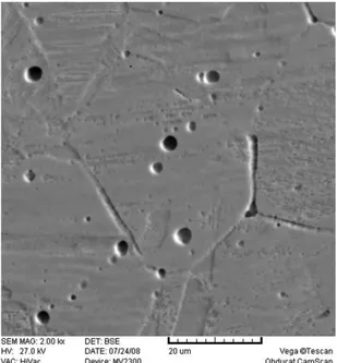
due to higher chromium and carbon contents. Figure 6 shows a SEM image of corroded M23C6-type carbides along grain boundaries of austenite in type-B weld metal. Considering the carbon content in as-received materials, 0.08 and 0.46 wt% for AISI304 and CK45, respectively, with normal dilutions, it is obvious that in weld metal of both specimen types, carbon content is kept low. The difference between carbon contents of weld metals and adjacent CK45 would establish a concentration gradient. Metallographic investigations showed a carburized region within the weld metal of type-B specimen adjacent to the fusion boundary and narrow decarburized zone in HAZ of CK45. Formation of carburized region in which carbides along the boundaries formed with higher density instead of other parts in weld metal with nonuniform distribution was a consequence of diffusion. In buttered specimens, carburized and subsequent decarburized areas were not observed as a result of barrier Ni layer.
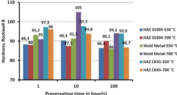
Both microstructures of weld metal and HAZ play an important role in controlling the mechanical properties of the weldment. Hardness in different areas of the weld samples was measured using Rockwell B and the mean values of at least ive measurements are compared in Figure 7. Comparisons concluded that due to existence of δ-ferrite next to austenite and higher amount of carbides along the grain boundaries in weld metal of as-weld type-B sample, hardness increased (93 vs. 84.5 HRB). Hardnesses of the AISI304 HAZ in both samples were almost equal and because of austenite grain growth values were lower than that for base material.
Increase in hardness values of CK45 HAZ in both designs attributed to microstructural evolutions. Figure 8 illustrates the microstructure of CK45 HAZ with different magniications. Based on igure, microstructure consisted of ferrite and pearlite as for as-received CK45. Average grain size of as-received CK45 was 10 µm whereas HAZ consisted of average 50 µm grains surrounded by connected network of grain-boundary ferrite while base material had discrete islands of ferrite in its matrix. The typical microstructure formed in weld metal of carbon steels consists of grain-boundary ferrite, Widmanstäten ferrite, acicular ferrite and microphases such as martensite, retained austenite or degenerate pearlite depending on the cooling rate below A3 temperature31,35,36. The phases
formed in HAZ have the same formation mechanism as
Figure 6. SEM image of corroded intergranular carbides in weld metal etched by 10%wt oxalic acid.
Figure 8. Optical micrographs showing the microstructures of CK45 HAZ consisting ferrite (white phase) and pearlite (dark phase) etched by Nital.
the phases occurring in weld metal except for acicular ferrite36. Also, Eroglu et al.31 reported that initial grain size of as-received material could strongly inluence the phase evolutions and their amounts in weld metal and HAZ. With grain-boundary ferrite, the original austenite boundaries are entirely disrupted, facilitating the site for the segregation of impurities35. Due to higher cooling rates experienced in welding, iner microstructure consisting of transgranular pearlite formed. Also higher cooling rates facilitated the formation of small amounts of microphases such as martensite and grain-boundary ferrites with higher carbon contents; however, they all could increase the hardness. SEM-EDX analyses were acquired from black-spots observed in CK45 HAZ (Figure 8b). Results represented higher amounts of O2 (1.60 %wt.), Mn (1.94 %wt.) and Fe (96.27 %wt.). Higher amounts of elements proved the inclusions segregation facilitated by formation of ferrite at grain boundaries of pearlite which transformed from initial austenite. Moreover, carbon diffusion in type-B specimens through fusion line did not impose noticeable change in CK45 HAZ hardness. PWHT performed at 550 and 700 °C for 1, 10 and 100 hours followed by air cooling. Figures 9 and 10 illustrate hardness change in PWHTed samples. In the type-A specimen at 550 °C, austenite grains growth reduced weld metal hardness. On the other hand, prolonging the preservation time increased the volume of carbides and impeded grain growth and after 100 hours, hardness elevated because formation of greater amounts of carbides overcome grain growth effect (comparing 76.7, 75.1 and 82.7 HRB for 1, 10 and 100 hours, respectively at 550 °C). At 700 °C, the precipitation of carbides and austenite grains growth accelerated simultaneously. Take into consideration
of low carbon content in weld metals of samples, during the prolonged preservation, grain growth dominated the effect of carbides volume increase and resulted in hardness reduction (comparing 88.2, 81.2 and 75.8 HRB for 1, 10 and 100 hours, respectively at 700 °C). The investigated trend in type-A specimen was also consistent for type-B. PWHT established two simultaneous challenging phenomena (grain growth and carbide formation) which induced hardness variations in which increasing temperature was more effective than preservation duration. The difference in type-A and -B specimens related to existence of ferrite. Ferrite-austenite interface had good potential for carbide precipitation32,33 and dissolution of ferrite during PWHT
followed by Cr content increase as a carbide promoter, get hardness increased. Comparing the hardness values in Figures 9 and 10 showed the factors’ effect. Figure 11 illustrates the connected network of carbides in type-B weld metal preserved at 700 °C for 10 hours. With increasing the time up to 100 hours, obvious change was observed in carbides thickness, hardness decrease and grain growth. Connected network of carbides incredibly decreased intergranular corrosion resistance and therefore subsequent service temperature range in these joints.
In order to investigate the inluence of microstructural evolutions on toughness, impact tests were conducted. The averages of at least ive experimented specimens of both types are shown in Table 4. Also, fractured surfaces were studied by means of SEM (Figure 12). Sigma-phase formation resulted in embrittlement. Talbot and Furman37 showed
that less than 5%vol. of sigma-phase in microstructure was effective in reducing the impact toughness by over 50%. Comparing the results in Table 4 depicted that energies achieved for weld metal samples were strongly proved no sigma-phase presence in as-weld samples. Lower acquired energies for type-B specimens were due to duplex microstructure which deteriorated toughness; however, type-A weld metal had higher toughness related to its single-phase austenitic microstructure along with its lower carbides volume. As discussed previously, δ-ferrite caused embrittlement and facilitates the formation of microphases such as carbides. Noticeable decrease in CK45 HAZ related to connected network of grain-boundary ferrite (Figure 8)
Figure 9. Effect of PWHTs on hardness of type-A specimens.
Figure 10. Effect of PWHTs on hardness of type-B specimens.
Table 4. Fracture energy results for impact tests.
Specimen Type Fracture Energy (J)
SS 304 SS 304 HAZ Weld Metal CK45 HAZ CK45
A
41.8 33.8 37.9 10.1 38.4
B 34.7 30.5 10.1
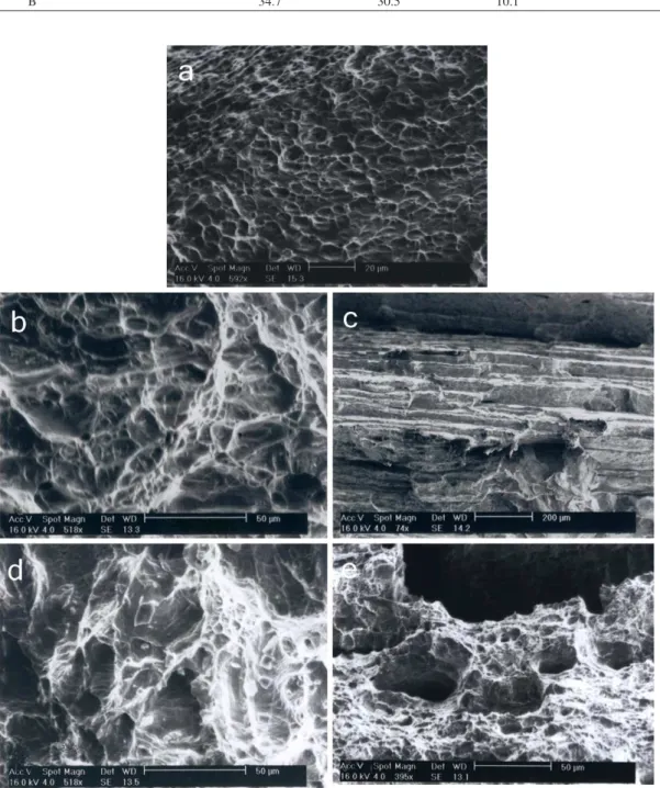
Figure 12. SEM fractography of type-A specimen; (a) weld metal, (b) stainless steel HAZ, (c) CK45 HAZ, (d) stainless steel base metal and (e) CK45 base metal.
which embedded tough pearlite. Connected web of ferrite grains formed due to high cooling rate which specimens experienced since discrete morphology of ferrites observed in as-received CK45. It has in the past been accepted that grain-boundary ferrite is detrimental to toughness, since it offers little resistance to cleavage crack propagation31.
grins boundaries strongly impaired impact toughness. Also, carbon migration in CK45 HAZ of type-B did not have positive effect on increasing toughness due to its higher primary carbon content (0.45 %wt.).
Fractography depicted that both type-A and type-B weld specimens fractured with dimples which justiied ductile fracture. Dimples diameters in type-B samples were lower than that for type-A due to higher strength and lower impact toughness of duplex structure. Figures 12b and 12c show SEM images of fractured AISI304 HAZ and CK45 HAZ surfaces. In carbon steel HAZ fracture occurred in certain crystal planes (stair-like structure) which was the evident of cleavage fracture attributed to lower toughness. Grain-boundary ferrite and impurities segregations at grain boundary sites caused brittle fracture. Stainless steel 304 HAZ and base metal were both had ductile fracture with dimple morphology.
4. Conclusions
Joining of CK45 to AISI304 stainless steel using GTAW technique has been performed and the microstructures and mechanical properties of weldments in as-weld and PWHTed conditions have been investigated. Weld metal in buttered specimen was completely austenitic while unbuttered sample had duplex structure. It was concluded that the Cr/Ni = 2.00 ratio was suficient for weld metal to solidify as ferritic-austenitic (FA type) which resulted skeletal morphology of δ-ferrite. Overlaying nickel layer
on CK45 and its partial melting in spite of reducing Cr/ Ni ratio in weld metal, completely prevented carbon diffusion and it was concluded that 4 mm thick buttering layer was appropriate to prevent subsequent carburized and decarburized regions next to fusion line in weld metal and CK45 HAZ, respectively. M23C6-type carbides observed immediately after welding along the grain boundaries in both type-A and type-B specimens. The volume fraction of carbides got increased by subsequent PWHTs.
PWHT at 550 and 700 °C for 1, 10 and 100 hours were performed to investigate effects of carbides precipitation, sigma-phase formation and grain growth. Grain growth and carbides precipitations were two simultaneous governing phenomena in both samples and their effect were in good agreement with hardness results. Governing factors surpassed each other in different treatments. Increasing the treatments’ temperature caused grain growth effect overcome carbides effect. PWHTed samples similar to as-welds did not contain sigma-phase since this was related to their lower Cr/Ni ratios and insuficient preservation times. Hardness and impact tests results also proved the microstructural evolutions since impact energies were not noticeably decreased in welds. Appreciable decrease in CK45 HAZ toughness was due to formation of connected web of grain-boundary ferrites and segregation of impurities. Dimple structure for both weld metals in fractography proved ductile fracture mode while dimples in type-B specimen were iner according to higher strength and lower absorbed energy of duplex microstructure.
References
1. D a v i s J R , e d i t o r . M e t a l s H a n d b o o k . O h i o : A S M International; 1993. Welding, brazing and soldering, v. 6.
2. Kearns WH. Dissimilar Metals. 7th ed. Miami: American Welding Society; 1982. Welding Handbook, v. 4, p. 514-547. 3. Paventhan R, Lakshminarayanan PR and Balasubramanian
V. Fatigue behaviour of friction welded medium carbon steel and austenitic stainless steel dissimilar joints. Materials & Design. 2011; 32(4):1888-1894. http://dx.doi.org/10.1016/j. matdes.2010.12.011
4. Ozdemir N. Investigation of the mechanical properties of friction-welded joints between AISI 304L and AISI 4340 steel as a function rotational speed. Materials Letters. 2005; 59(19-20):2504-2509. http://dx.doi.org/10.1016/j.matlet.2005.03.034
5. Emerson RW and Hutchinson WR. Welded joints between dissimilar metals in high temperature service. Welding Journal. 1952; 31(5):126s-141s.
6. Cox CW and Kiser SD. Fusion welding of dissimilar m e t a l s f o r h i g h - t e m p e r a t u r e s t r e n g t h . We l d i n g Journal. 1992; 71(5):61s-70s.
7. Rutherford JJB. Welding stainless steel to carbon or ferritic steel. Welding Journal. 1959; 38(1):19s-26s.
8. Joseph A, Rai SK, Jayakumar T and Murugan N. Evaluation of residual stresses in dissimilar weld joints. International Journal of Pressure Vessels and Piping. 2005; 82(9):700-705. http://dx.doi.org/10.1016/j.ijpvp.2005.03.006
9. Arivazhagan N, Singh S, Prakash S and Reddy GM. An assessment of hardness, impact strength and hot corrosion behavior of friction-welded dissimilar weldments between AISI 4140 and AISI 304. International Journal of Advanced
Manufacturing Technology. 2008; 39: 679-689. http://dx.doi. org/10.1007/s00170-007-1266-7
10. Jafarzadegan M, Feng AH, Abdollah-zadeh A, Saeid T, Shen J and Assadi H. Microstructural characterization in dissimilar friction stir welding between 304 stainless steel and st37 steel. Materials Characterization. 2012; 74: 28-41. http://dx.doi. org/10.1016/j.matchar.2012.09.004
11. Celik A and Alsaran A. Mechanical and Structural Properties of Similar and Dissimilar Steel Joints. Materials Characterization. 1999; 43(5):311-318. http://dx.doi. org/10.1016/S1044-5803(99)00045-5
12. Eckel JF. Diffusion across dissimilar metal joints. Welding Journal. 1964; 43(4):170s-178s.
13. Huang ML and Wang L. Carbon migration in 5Cr-0.5Mo/21Cr-12Ni dissimilar metal welds. Metallurgical and Materials Transactions A. 1998; 29(12):3037-3046. http://dx.doi. org/10.1007/s11661-998-0211-1
14. Lippold JC and Kotecki DJ. Welding Metallurgy and Weldability of Stainless Steels. New Jersey: John Wiley & Sons; 2005. p. 141-229.
15. Kou S. Welding Metallurgy. 2nd ed. New Jersey: John Wiley & Sons; 2002. p. 431-454. http://dx.doi.org/10.1002/0471434027. ch18
16. Barnhouse EJ and Lippold JC. Microstructure/Property relationships in dissimilar welds between duplex stainless steels and carbon steels. Welding Journal. 1998; 77(12):477s-487s. 17. Hull FC. Delta ferrite and martensite formation in stainless
steels. Welding Journal. 1983; 52(5):193s-203s.
Welding International. 1991; 5(5):409-413. http://dx.doi. org/10.1080/09507119109446763
19. Christoffel RJ and Curran RM. Investigation of carbon migration during elevated temperature service for determining the propensity of a number of alloys to carbon migration. Welding Journal 1956; 35(9):457s-465s.
20. Marshall P. Austenitic Stainless Steels Microstructure and Mechanical Properties. London: Elsevier; 1984.
21. Davison RM, DeBold T and Johnson MJ. Metals Handbook. Ohio: ASM International; 1993. v. 13, p. 547-565.
22. Vander Voort GF and James HM. Metals Handbook. Ohio: ASM International; 1993. v. 9, p. 279-296.
23. V i t e k J M a n d D a v i d S A . T h e s i g m a p h a s e transformation in austenitic stainless steels. Welding Journal. 1986; 65(4):106s-111s.
24. Bala Srinivasan P, Muthupandi V, Dietzel W and Sivan V. Microstructure and corrosion behavior of shielded metal arc welded dissimilar joints comprising duplex stainless steel and low alloy steel. Materials Engineering and Performance. 2006; 15(6):758-764. http://dx.doi. org/10.1361/105994906X150902
25. Berchmans LJ, Muralidharan S, Rengaswamy NS, Natarajan S, Sivan V and Iyer SV. Stress corrosion cracking and hydrogen embrittlement susceptibility studies on modiied 9Cr-1Mo steel weldments in acidic and neutral media. British Corrosion Journal. 1996; 31(3):223-226. http://dx.doi. org/10.1179/000705996798114563
26. Majid TM, Sultan SAR, Mahdi SD and Jasim S. Effect of microstructure on corrosion rate of underwater steel welds. Corrosion. 1990; 46(1):37-42. http://dx.doi. org/10.5006/1.3585064
27. Hemmingsen T, Hovdan H, Sanni P and Aagotnes NO. The inluence of electrolyte reduction potential on weld corrosion. Electrochimica Acta. 2002; 47(24):3949-3955. http://dx.doi. org/10.1016/S0013-4686(02)00366-3
28. Zumelzu E and Cabezas C. Study on welding such dissimilar materials as AISI 304 stainless steel and DHP copper in a sea-water environment. Inluence of weld metals on corrosion. Journal of Materials Processing Technology. 1996; 57(3-4):249-252. http://dx.doi.org/10.1016/0924-0136(95)02073-X
29. American Society for Testing and Materials - ASTM. ASTM Standards E23: Standard Test Methods for Notched Bar Impact Testing of Metallic Materials. ASTM International; 1990. v.03.01.
30. Lippold JC and Savage WF. Solidiication of austenitic stainless steel weldments, part 1 - a proposed mechanism. Welding Journal. 1979; 58(12):362s-374s.
31. Eroglu M, Aksoy M, Orhan N. Effect of coarse initial grain size on microstructure and mechanical properties of weld metal and HAZ of a low carbon steel. Materials Science and Engineering: A. 1999; 269: 59-66. http://dx.doi.org/10.1016/ S0921-5093(99)00137-9
32. Davis JR, editor. ASM specialty handbook: stainless steels. Ohio: ASM International; 1994.
33. Stickler R and Vinchier A. Morphology of grain-boundary carbides and its influence on intergranular corrosion of 304 stainless steel. Transactions of American Society of Metals. 1961; 54:362-380.
34. Plaut RL, Herrera C, Escriba DM, Rios PR and Padilha AF. A short review on wrought austenitic stainless steels at high temperatures: processing, microstructure, properties and performance. Materials Research. 2007; 10(4):453-460. http:// dx.doi.org/10.1590/S1516-14392007000400021
35. Bhadeshia HKDH and Svensson L-E. Modelling the Evolution of Microstructure in Steel Weld Metal. In: Cerjak H and Easterling KE, editors. Mathematical Modelling of Weld Phenomena. London: The Institute of Materials; 1993. v. 1, p. 109-182.
36. Easterling KE. Introduction to the Physical Metallurgy of Welding. London: Butterworth-Heinemann; 1992.
37. Talbot AM and Furman DE. Sigma formation and its effect on the impact properties of iron-nickel-chromium alloys. Transactions of American Society of Metals. 1953; 45:429-440.