The Inluences of Martensitic Transformations on Cavitation-Erosion Damage Initiation
and Pitting Resistance of a Lean Austenitic Stainless Steel
Kai Yuan Wang a; Kin Ho Loa,b*; Chi Tat Kwoka,b; Man Meng Wonga; In Wa Ionga; Wenji Aia
Received: July 16, 2015; Revised: August 23, 2016; Accepted: September 07, 2016
This paper looks into the inluences of martensitic transformations on the cavitation-erosion (CE) damage initiation mechanism and pitting corrosion resistance of a lean austenitic stainless steel. The ε and α’ martensites are prime sites of CE damage initiation for this steel, whereas grain boundaries are more favourable damage initiation sites for other similar steels. The profusion of ε and α’ results in fast surface roughening during the CE process, which may cause a compromise in performance when this steel (or similar steels that have the same CE damage mechanism) is used for such applications as hydro-machinery or piping. ε and α’ also detrimentally afect the pitting resistance of this steel and so they are expected to afect CE resistance adversely due to the synergism between CE and corrosion.
Keywords: Cavitation erosion; Lean austenitic stainless steel; Martensitic transformation; Pitting corrosion
* e-mail: [email protected]
1. Introduction
In applications involving high-speed lows, such as turbines and piping, cavitation erosion (CE) is always a problem. In piping systems, for instance, when there is a decrease in pipe diameter in a certain section, the local low speed will increase and the luid pressure will drop. If the pressure drop is suicient, cavitation may occur and the inner wall of the pipe will experience erosion attacks1. The piping system may then sufer from vibration or the luid conveyed in the pipe may experience an increase in pipe wall friction.
While carbon steels have been used in applications in
which CE is anticipated2, stainless steels are more preferred due to their higher corrosion resistance. In this regard, the
martensitic grades3 and the precipitation-hardening grades3, 4 of stainless steels have been considered useable. On the other hand, views on the austenitic grades appear to be varied. The CE resistance of austenitic stainless steels (AusSSs) has
been stated to be good by some researchers3, 4, but inferior by others5. Enhancement of CE resistance of the austenitic grades has been shown to be viable using surface engineering techniques, such as friction-stir welding6, laser treatments7, and nitriding8.
The lean AusSSs have been gaining popularity in recent
years, as relected by the continual development of new varieties. This popularity arises in a large part from their lower costs. Typically, these steels are high in Mn and N, but low in Ni which is expensive. The lean AusSSs (and the austenite phase of lean duplex stainless steels9) have a propensity for martensitic transformation, either through
cooling10 or plastic deformation11. The transformation
routes may be from austenite (γ) to the body-centred-cubic martensite (α’) directly, or through the
hexagonal-close-packed ε martensite, or via deformation twins12.
When martensitic transformation occurs during the CE process, it provides a cushioning efect by taking up some of the impact energy from the collapsing bubbles. In this regard, martensitic transformation is considered beneicial, as it may reduce mass loss rate during the CE process13-15.
Quite frequently, grain boundaries are reported as the prime initiation sites of CE damage13-15. The roles of ε and α’ on
CE damage initiation, on the other hand, appear to be less examined.
When a material undergoes CE in a corrosive medium, a synergism exists between CE and corrosion16, resulting in accelerated material attack. Because austenite and the α’ martensite may form a galvanic couple17, the α’ induced during the CE process is bound to detrimentally afect CE resistance.
The present work is not a chronicle of the CE process of a lean, high-Mn AusSS, as this has already been reported in depth for similar steels. Instead, this work looks into the inluences of ε and α’ martensites on CE damage initiation, damage morphology and pitting corrosion resistance of a Mn-containing AusSS in 3.5 % NaCl, with the view of
gaining a deeper understanding on the role played by ε and
α’ on the CE damage of lean AusSSs.
2. Experimental Details
The major elements present in the lean, high-Mn (low-Ni) AusSS used in this work are shown in Table 1. The exact designation of the steel is unknown, however. This a Department of Electromechanical Engineering, University of Macau, Macau
All the samples for CE tests were solution-treated at 1100°C for 1 h and then then quenched rapidly into water. Vibratory CE tests were conducted using a sonicator according to ASTM G 32-06 at 25 ºC in 3.5 % NaCl. CE tests were interrupted at diferent times for observations of the surface damage morphology of samples using a Hitachi S3400N Type I scanning electron microscope (SEM). Potentiodynamic anodic polarisation tests were done in 3.5 % NaCl with a scan rate of 1 mV/s starting from 0.4 V under the open-circuit potential. For each condition, at least 3 polarisation tests were done. The polarisation curves presented in this work show the general trends of the polarisation tests. The samples for polarisation tests were variously solution-treated between
1100 °C and 1300°C for 1 h and then water-quenched, with
the view of assessing the efect of grain size on martensitic transformation and pitting corrosion resistance. Grain size measurements were done with a Leica Image Analyser (Model DMI3000M). The identiication of ε and α’ was done using X-ray difractometry (XRD) with a Rigaku MiniFlex 600 difractometer (CuKα) with a scan rate of 0.1 degree/s.
3. Results and Discussions
3.1. Inluence of ε and α’on CE pit initiation and
damage morphology
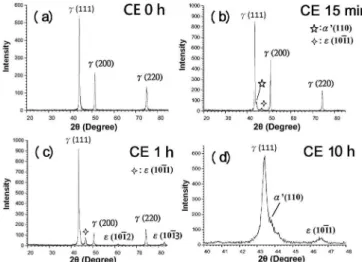
According to XRD results, some as-solution-treated samples contained martensite, whereas some did not. The samples chosen for CE tests were those that did not contain any pre-existing martensite. The XRD spectra taken from one such originally martensite-free sample after it had gone through diferent CE times are shown in Figure 1. The variability in presence of martensite was chiely due to the slight batch-to-batch variation in composition.
Before undergoing the CE process, the sample surface was lat and smooth (Figure 2). After undergoing the CE process for 15 min, surface of the sample still looked relatively smooth under the SEM, but both ε and α’ were already detectable (Figure 1(a) and (b)).
Under the SEM, traces of ε and α’ could be seen to have formed in some regions. In other regions, these traces could only be vaguely discerned at high magniications (Figure 3).
time (Figure 4). Difraction peaks pertaining to ε are more
prominent than those pertaining to α’ throughout the CE process (Figure 1(b) and (c)). Nevertheless, difractions peaks pertaining to α’ did exist throughout the CE process (Figure 1(d)).
In Figure 4, tiny CE pits may be seen to have formed on martensite traces (ε and α’). For the twin boundaries and grain boundaries, however, no noticeable CE pits had formed by this time. Therefore, although martensitic transformations are beneicial as far as mass loss rate is concerned13-15, ε and
α’ are the most favourable sites for CE damage initiation in this case. The relative importance of ε and α’ for CE pit initiation, however, cannot be determined, as the two types of martensite are indistinguishable under the SEM. For this
reason, ε and α’ will be referred to collectively as martensite
traces hereinafter.
Soon after the CE process began, numerous martensite traces had been produced in the sample. This profusion of martensite traces facilitated easy coalescence of the CE pits that had formed on them. For two CE pits that were close to each other, the small amount of material between them
could be easily ploughed out, resulting in pit coalescence
(Figure 5).
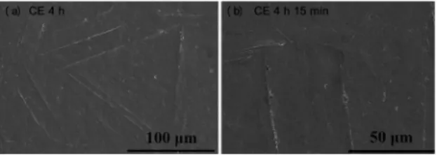
The higher susceptibility of martensite traces to CE damage initiation than twin and grain boundaries may be appreciated further by looking at the sample that had gone through the CE process for about 4 hours. In Figure 6, it is shown that the CE pits that had formed on twin boundaries were still in their infancy. Note that by this time, both twin and grain boundaries had been revealed more clearly. In Figure 6(b), the grain boundary above the two twin boundaries had not sustained too much damage.
Figure 1: XRD spectra of an originally martensite-free sample that went through the CE process for diferent durations
Figure 2: Appearance of a sample prior to undergoing the CE process.
Figure 3: Appearance of a sample that had undergone the CE process for about 15 min.
Figure 4: Formation of tiny CE pits on the martensite traces of a sample that had undergone the CE process for 1 h.
Figure 5: CE pits formed on martensite traces and their coalescence in a sample that had undergone the CE process for 3 h 15 min.
compared with the twin and grain boundaries is obvious. The CE damage associated with twin and grain boundaries in another region of the sample is demonstrated in Figure 7(b), and it may be seen that there was no signiicant dig-out of material along these boundaries.
As mentioned previously, innumerable martensite traces
were produced during the CE process, which resulted in their
close proximity to each other. Consequently, the CE pits that had formed on the martensite traces could join easily, thereby forming craters that propagated roughly perpendicularly to the martensite traces (Figure 8).
Figure 7: The surface morphology of a sample that had undergone the CE process for 16.5 h.
Figure 8: Growth of CE craters nearly perpendicular to martensite traces on a sample that had undergone the CE process for 18.5 h.
shock waves generated by collapsing bubbles. Hence, the ductile peeling-of of material involved small bits and lakes, resulting in a damage morphology as shown in Figure 9. The main damage feature is wide-spread peeling-of of small and shallow bits of material. Once a small chunk of material is
removed, ε and α’ would form in the newly exposed material
within a short time. And the above process will repeat itself. Eventually, a grainy damage morphology consisting of small globs would result (Figure 10). The grainy morphology shown in Figures 9 and 10 (a) is revealed more clearly in Figure 10(b), which is a close-up view of the region inside the rectangle in Figure 10(a). By this time, twin and grain boundaries had also sustained noticeable CE attacks.
In an Fe-16Cr-0.5C-3Mn AusSS, it was found using electron back-scattered difraction (EBSD) that α’ had formed in its grain interiors during the CE process. But in the vicinity of grain boundaries, α’ was nearly absent14. The scarcity of α’ formation near the grain boundary regions in this steel resulted in damage initiation at its grain boundaries. The grain interiors of this steel, on the other hand, did not
Figure 9: The surface of a sample that had undergone the CE process for about 30.5 h.
Figure 10: The grainy damage morphology of a sample that had undergone the CE process for 57 h (a) and a close-up view of the region inside the rectangle (b).
sufer from extensive CE damage because α’ formation dissipated some of the impact energy from the collapsing bubbles. It must be noted that the α’ of this steel did not appear to be damage initiation site. In the Fe-16Cr-0.5C-3Ni AusSS investigated in the same work, extensive slip bands, instead of α’, had formed during the CE process14. These slip bands were found to be favourable damage initiation sites. The paucity of α’ formation in this steel was found to be responsible for its poorer CE resistance relative to its Fe-16Cr-0.5C-3Mn counterpart14. Similar results have also been observed in a series of Mn-containing AusSSs and Ni-containing AusSSs13.
For the lean steel used in this work, however, the situation seems to be a mix-up of those of the two steels mentioned in the preceding paragraph. For the present steel, ε and α’, instead of slip bands, had formed and they extended all the way up to the grain boundaries. However, these two types of martensites seem to be favourable damage initiation sites, as opposed to the Fe-16Cr-0.5C-3Mn steel mentioned above. For the present lean steel, the formation of ε and α’ almost everywhere led to fast roughening of its surface, which may cause the problems mentioned in Introduction when this steel (or similar steels) is used for hydromachinery or piping applications.
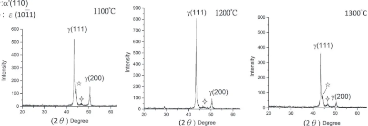
Figure 11: XRD spectra of the martensite-containing samples after water-quenching from diferent solution-treatment temperatures.
lines. For the present lean steel, damage appeared to get initiated at both the twin and grain boundaries almost at the same time. From the discussion above, it may be seen that there exist various mechanisms of CE damage initiation for these Mn-containing AusSSs.
Here, it must be emphasised that although ε and α’ were found to be favourable initiation sites of CE damage for the present lean steel, it does not mean martensitic transformations are not beneicial to CE resistance. This is because the extent of surface damage may not directly correlate with mass loss rate. For example, for two AISI 304 AusSSs having diferent grain sizes, the one having a smaller grain size was found to have a lower mass loss rate during the CE process19. However, as far as the extent of surface damage is concerned, the AISI 304 steel having a small grain size was more severely attacked in comparison to the one having a bigger grain size, as grain boundaries were the main damage initiation sites19.
3.2. Inluence of ε and α’ on pitting corrosion
resistance
Upon water-quenching between 1100ºC and 1300 ºC, some of the samples contained α’ and ε (Figure 11).
For these martensite-containing samples, their pitting potentials were reduced noticeably compared with their martensite-free counterparts that were quenched from the same temperature (Figure 12).
When the solution-treatment temperature was raised to 1300ºC from 1100ºC, the pitting potential decreased progressively (Figure 13). The average grain size, however, increased markedly. An increase in grain size is detrimental
to pitting corrosion resistance20. According to Ralston et al.21, a metal that passivates in a given medium will be able to do so more easily when its grain size decreases, as an increase in surface area is conducive to passivation. This is certainly applicable to the present lean steel in 3.5 % NaCl. An increase in grain size also facilitates martensitic transformation22,
Figure 12: The inluence of α’ and εon the potentiodynamic anodic polarisation behaviour of the lean steel after quenching from 1100°C.
Figure 13: Change in potentiodynamic anodic polarisation behaviour of the lean steel with solution-treatment temperature.
23. Both factors are responsible for the reduction in pitting potential as depicted in Figure 13.
5. Acknowledgements
The present work was inancially supported by Fundo para o Desenvolvimento das Ciências e da Tecnologia (FDCT) (Grant Nos.: 069/2012/A3).
6. References
1. Nagaya Y, Nurase M, Mizuyama S, Hattori S. Evaluation of incipient cavitation erosion for pipe wall at downstream of an oriice. In: Proceedings of the 7th International Symposium on
Cavitation; 2009 Aug 16-20; Ann Arbor, Michigan, USA. p. 1-5.
2. Ferreño D, Álvarez JA, Ruiz E, Méndez D, Rodríguez L, Hernández D. Failure analysis of a Pelton turbine manufactured in soft martensitic stainless steel casting. Engineering Failure Analysis. 2011;18(1):256-270.
3. Garverick L. Corrosion in the Petrochemical Industry. Materials Park: ASM International; 1994.
4. Khatak HS, Raj B, eds. Corrosion of Austenitic Stainless Steels:
Mechanism, Mitigation and Monitoring. Cambridge: Woodhead
Publishing; 2002.
5. Hajian M, Abdollah-zadeh A, Rezaei-Nejad SS, Assadi H, Hadavi SMM, Chung K, et al. Improvement in cavitation erosion resistance of AISI 316L stainless steel by friction stir processing.
Applied Surface Science. 2014;308:184-192.
6. Chiu KY, Cheng FT, Man HC. Laser cladding of austenitic stainless steel using NiTi strips for resisting cavitation erosion.
Materials Science and Engineering: A. 2005;402(1-2):126-134.
7. Sun GF, Zhang YK, Zhang MK, Zhou R, Wang K, Liu CS, et al. Microstructure and corrosion characteristics of 304 stainless steel laser-alloyed with Cr–CrB2. Applied Surface Science.
2014;295:94-107.
8. dos Santos JF, Garzón CM, Tschiptschin AP. Improvement of the cavitation erosion resistance of an AISI 304L austenitic stainless steel by high temperature gas nitriding. Materials Science and
Engineering: A. 2004;382(1-2):378-386.
and characteristics of deformation induced martensite during low cycle fatigue behaviour of austenitic stainless steel. Materials
Science and Engineering: A. 2011;528(27):7909-7914.
13. Park MC, Kim KN, Shin GS, Yun JY, Shin MH, Kim SJ. Efects of Ni and Mn on the Cavitation Erosion Resistance of Fe–Cr–C–Ni/ Mn Austenitic Alloys. Tribology Letters. 2013;52(3):477-484. 14. Park MC, Shin GS, Yun JY, Heo JH, Kim DI, Kim SJ. Damage
mechanism of cavitation erosion in austenite→martensite phase
transformable Fe–Cr–C–Mn/Ni alloys. Wear. 2014;310(1-2):27-32. 15. Park MC, Kim KN, Shin GS, Kim SJ. Efects of strain induced
martensitic transformation on the cavitation erosion resistance and incubation time of Fe–Cr–Ni–C alloys. Wear. 2012;274-275:28-33.
16. Kwok CT, Cheng FT, Man HC. Synergistic efect of cavitation erosion and corrosion of various engineering alloys in 3.5% NaCl solution. Materials Science and Engineering: A. 2000;290(1-2):145-154.
17. Xu C, Hu G. Efect of deformation-induced martensite on the pit propagation behavior of 304 stainless steel. Anti-Corrosion
Methods and Materials. 2004;51(6):381-388.
18. Niederhofer P, Huth S. Cavitation erosion resistance of high interstitial CrMnCN austenitic stainless steel. Wear. 2013;301(1-2):457-466.
19. Bregliozzi G, Di Schino A, Ahmed SIU, Kenny JM, Haefke H. Cavitation wear behaviour of austenitic stainless steels with diferent grain sizes. Wear. 2005;258(1-4):503-510. 20. di Schino A, Barteri M, Kenny JM. Efects of grain size on the
properties of a low nickel austenitic stainless steel. Journal of
Materials Science. 2003;38(23):4725-4733.
21. Ralston KD, Birbilis N, Davies CHJ. Revealing the relationship between grain size and corrosion rate of metals. Scripta
Materialia. 2010;63(12):1201-1204.
22. Takaki S, Fukunaga K, Syarif J, Tsuchiyama T. Efect of grain reinement on thermal stability of metastable austenitic steel.
Materials Transactions. 2004;45(7):2245-2251.