INCREASING THE CYCLIC STRENGTH OF THREADED JOINTS
THROUGH THE UNLOADING OF CRACKED SECTIONS
A. Krenevičius*,#, R. Kačianauskas*, M. Leonavičius*, D. Hui**, L. Feo****Department of Strength of Materials, Vilnius Gediminas Technical University,
Saulėtekio al. 11, Vilnius, LT-10223, Lithuania
**University of New Orleans and NASA National Center for Advanced Manufacturing, USA
***Department of Civil Engineering, University of Salerno, 84084 Fisciano, Italy
(Received 05 December 2011; accepted 04 June 2012)
Abstract
The cyclic strength of the axially loaded threaded joints is considered and the procedural method to increase their lifetime through the unloading of cracked sections is presented. The method operates by varying the mutual positions of the stud and the nut. It was shown how to exploit resources of the threaded joint after opening of the crack without reduction of the safety. The developed mathematical model allows control the accumulation of the fatigue damage as well as the crack growth in the roots of the stud thread. Increase of the cyclic lifetime is theoretically evaluated by the ratio of the numbers of loading cycles required to initiate cracks in the roots of unengaged and the most dangerous engaged turns of the stud. Performance of the elaborated technique is demonstrated by considering the crack growth in depth of the nut. The relative safety of the unloaded cross-sections containing cracks is studied. Comparison of the presented developments with standard safety requirements is presented.
Keywords: Threaded joints; Fatigue; Damageability; Crack
#Corresponding author: [email protected]
M i n i n g a n d M e t a l l u r g y
J. Min. Metall. Sect. B-Metall. 48 (2) B (2012) 291 - 307
DOI:10.2298/JMMB111205029K
1. Introduction
Understanding of the nature of fatigue
phenomena is fundamental issue
continuously considered by many
researches. Nowadays, the emphasis is given towards investigation of microstructural
effects, understanding of fatigue
strength may be critical in a reliable engineering design while fatigue damage of smaller elements can cause the failure of complex structural systems or limit the cyclic lifetime of the structure as a whole.
Performance of threaded joints under cyclic loading plays an important role in the integrity and functionality of equipment and machines explored in various industries. The fatigue behaviour of threaded joints is contributed by additional factors related to specific geometry and stress distribution. More definitely, accumulation of damage, crack initiation and further complete fatigue failure of the stud-nut joint occurs in the stud cross-section at the root of the turn engaged with the first full profile turn of the nut near its bearing surface.
There are various traditional engineering techniques reported in earlier literature [5-7] to increase fatigue life which decrease the notch effect of the thread. By applying technological measures, the decreasing of the stress concentration can be achieved by either increasing the thread root radius or applying an improved profile of the thread turns [8, 9]. In addition, roll-formed threads after heat treatment have greater fatigue strength compared to machined (turned, milled, ground) threads. The fatigue life of the threaded joint can be increased also by using microstructurally optimized bolts with graded grain size [10].
Various constructional innovations have been elaborated to improve the load distribution in threads. For example, there are nuts with tapered threads [11, 12], nuts with bevel at the loaded face [13] or stud threads with gradually reduced height in the direction of the bearing surface of the nut
[14]. Applying such nuts or bolts, the stresses in the thread roots are reduced rather effectively.
However, increasing of the cyclic lifetime of the threaded joints without increasing their sizes is still a significant challenge in engineering design. Therewith, deeper knowledge about distribution of internal forces in the joint is of major importance. Series of the first results considering the distribution of loads in the nut—bolt connection were reported in [15-17]. Here, the finite element method was employed.
Many studies on threaded connections have been performed in relation to the fatigue. A review of the earlier contributions in development of the bolt fatigue-life prediction methods is presented in review by Patterson [18]. A review of experimental method to study the fatigue behavior of bolt–nut threaded connections under a state of cyclic tensile loading is given in [19].
The capacity of joint to resist cyclic load fatigue up to the complete failure of the stud is the long time period. Two dominant stages may be distinguished. The first stage comprises accumulation of the fatigue damage, while the second stage runs from the instant of the macrocrack opening. The experimental procedure to study both of the stages of initiation and crack growth is elaborated in [19, 20]. On the basis of earlier findings, two possible sources in order to increase the lifetime of a conventional threaded joint may be considered.
both increasing towards the bearing surface of the nut. It is obvious that stud segment located inside of the connector is loaded only by the axial tension force. Consequently, the stress in unengaged thread within this segment is considerably smaller compared to the risky stud turn near the bearing surface of the nut [16]. In summary, the capacity of the unengaged threads to accumulate the fatigue damage over the whole operation time remains unused. The possibility to prolong the fatigue life by shifting risky stress concentration just before opening of the crack is already considered in [21, 22] where the optimal number of cycles is evaluated by solving optimisation problem.
A further resource of prolongation of the fatigue life is ability to control the fatigue behaviour after opening the crack. On the basis of conducted own experiments [20] the crack propagation stage is usually longer than the first stage of the fatigue crack initiation. It should be noticed that the macrocrack growth stage of the stud is eliminated from the design standards of the stud fatigue life due to high safety requirements of the threaded joints [23, 24]. According to this concept, the propagation of the crack is not allowable for higher safety reasons; therefore this is important resource is also unused and remains beyond the consideration.
In this article the procedural method through the unloading of the cracked sections is proposed in order to increase the cyclic lifetime of threaded joints. By changing the mutual positions of the stud and nut in a threaded joint, it is possible to exploit both above mentioned resources of the threaded joint after opening of the crack
without reduction of the safety.
The paper is organized as follows. The concept of the crack unloading method is described in Section 2. The crack initiation indexes defining the number of loading cycles required to initiate cracks in the roots of the stud turns are defined in Section 3. The performance of the elaborated technique is demonstrated in Section 4. Crack growth in depth of the nut analysis is given in Section 5, where the unloading of the crack leading to prolongation of fatigue life is clearly demonstrated. The relative safety of the unloaded cross-sections containing cracks is studied in Section 6 and the final conclusions are formulated in Section 7.
2. The concept and mathematical model of increasing the cyclic strength life of threaded joints
The concept to increase the cyclic strength of threaded joints under tension is elaborated by considering the variation of the stud turns load and corresponding stresses along the symmetry axis of the joint. It is well known [5, 6] that the maximum stresses as well as the maximum accumulation rate of the cyclic damages occur in the stud turn root which is engaged with the first full-profile turn of the nut. Consequently, the stresses in the stud turn roots could be controlled by changing the position of the nut in an appropriate way.
The method to increase the cyclic strength of the threaded joints proposed here makes it possible to reduce the loading level of the damaged cross sections of the stud by varying the mutual position of stud and nut.
related to its ability to withstand accumulated fatigue under cyclic loading. The entire fatigue life of the joint is defined
by the critical number of load cyclesN0. This
parameter indicates the safety threshold to withstand fatigue damage of the joint. Critical damage of the joint is characterised by the initiation of the fatigue crack which occurs at the stud turns under a cyclic load.
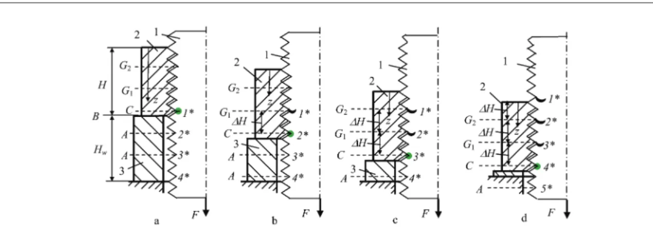
The unloading concept of the damaged turns of the stud containing cracks is illustrated in Figure 1. Let us consider an axisymmetric cross-section of the threaded
joint subjected by the cyclic tension force F
as a one-dimensional problem with respect to
axis z. Here, the stud is denoted by numeric
symbol 1, the nut by 2 and the bush-washer by 3. The nut geometry is characterized by
its height H.Technically, the unloading may
be controlled by periodically decreasing the height of the bush-washer.
Evaluation of the local damage and its role for the entire fatigue life of the threaded joint is utilized by considering two specific
sections C and A, respectively. Firstly, we
distinguish the most risky section of the joint
denoting it hereafter with C.It is well known
that only in this section of the joint, the highest load occurs in the turn of the stud engaged with the first full-profile turn of the nut. Thus, the critical cyclic damage accumulation runs in the critical cross-section of the stud located in the level of the
risky section C of the joint. Consequently,
the entire fatigue life of the stud is related to
section C and it is defined by the critical
number of load cyclesN0=N0C.
It is obvious that, the critical cross-section of the stud is related to the fixed relative position of the nut. It may move by shifting
the nut. The available critical sections of the joint positioned below the nut, i.e. in the area of the bush-washer, are denoted hereafter as
sectionsA.
It is known that the local stresses which act on the unengaged turns of the stud are about two times less here than those in the
level of the risky section C of the joint.
Therefore, the fatigue life for the unengaged stud is expressed by the critical number of cycles N0A, where N0A>N0C.
In light of the above approach, the
number of loading cycles N0A and N0C until
crack initiation in the roots of the stud turns, are decisive parameters characterizing the fatigue life of the threaded joint. Control of the fatigue loading is implemented in the following manner. The initial position of the
nut with respect to axis z is defined by the
initial height Hw of the bush-washer
(Fig. 1a). Thus, the risky section of the joint
denoted by C coincides with the stud root
point 1*. This means that the first cyclic
loading period T1 runs until the crack
initially appears in the root. During the first
loading period, the total fatigue life N0C
however, is explored by the capacity of a
single cross-section of the stud. Thus, T1 is
characterised by N0C.
Periodical changing of the mutual position of the stud 1 and the nut 2 is illustrated in Figs. 1b and 1c. The new positions of the nut are fixed by an incremental procedure which is implemented
by a sequential reduction the height Hw of
the bush-washer 3 with the height increment
DH. It should be noticed that the changing
During the first shifting, the nut is being
moved by a distance of ΔH. Consequently,
the cracked turn 1* of the stud is shifted into the depth of the nut and occurs in the level of
section G1 (Fig. 1b). Therewith, the
cross-section of the stud with the initial crack is unloaded and moves from critical to a safe state with a sufficiently lower load level.
Simultaneously, the damaging nut turn located in section C engages with the other, previously unengaged turn 2* of the stud. The crack is now being formed in the root of this stud turn. The crack is initiated here after
the second cyclic loading period
characterised byT2loading cycles. The third
positioning period is characterised by the presence of two cracked turns of the stud with roots 1* and 2*. Since they are engaged
with the thread of the nut in the levels G1and
G2of the nut, the cracks growing are almost
frozen. As in the previous case, the fatigue damage is accumulated in root 3* of the stud turn engaged with the most damaging turn of
the nut located in the nut section C. Here, the
cross-section of the stud can withstand T3
loading cycles until the initiation of the crack.
If the height of the bush-washer is greater than the nut height, the stud cracked cross-section can occur in the unloaded position behind the free end of the nut. This case is illustrated in Fig. 1d where the stud cross-section with cracked root 1* occurred in the unloaded position.
The unloading procedure of the cracked cross-sections of the stud when the nut is
being shifted over the same distance ΔHmay
be repeated several times. We denote each of
the cyclic loading periods by subscript j
(j=1, 2,…, u), where uis the total number of
loading periods. In terms of the above
notation, we can shift the nut u-1 times and
allow for the opening of ucracks in the roots
of the stud turns.
Formally, only the initial height of the
bush-washer Hwpredefines the total number
of the cyclic loading periods upon the
condition Hw≥(u-1)ΔH. From the point of
view of the cyclic strength, shifting the nut by rotating should be stopped when cracks occur in unengaged turns left in the cavity of the bush-washer. It means that total number of the loading cycles should remain below the critical value
Fig. 1. Illustration of turns unloading by the sequential change of the nut positions using the bush-washer of variable height: a) initial position, b, c) intermediate positions, d) final position: 1 – stud, 2 – nut, 3 – bush-washer; ● - crack initiation, ~ - small cracks
Tsum Tj
j u
(1)
The above condition predefines the limit of the maximal number of loading cycles
Tsum,max=N0A, while fatigue life could be
maximally increased by N0A/N0Ctimes.
The mathematical description of the damage accumulation is based on the relations of conventional fatigue. Let us
consider the most critical cross-section i=1*
of the stud which undergoes damaging fatigue due to its turn engagement with the
nut turn in the risky section C during one
loading cycle. In addition, the local stress state in root of this turn during each of the loading periods is assumed to be stationary.
The damageability of cross-section 1* of the stud is characterised by a damage
accumulation rate
C which may be related
to the critical number of loading cycles as: (2) In the initial loading period characterised
by T1 cycles the damage amount
accumulated in the stud section i=1* could
be evaluated as the product DC=T1×
C. The damageability of unengaged turns of
the stud positioned in sections Aof the joint,
i.e. below the nut in the cavity of the bush-washer, may be considered in the same manner. It is characterised by a damage
accumulation rate
.A which may be related
to the critical number of loading cycles as: (3) In the initial loading stage, the damage amount accumulated in the stud
cross-section i >1*, i.e. in roots i=2*, 3*,…u*,
could be evaluated as DA=T1×
A.
This approach may be utilised for the characterisation of damageability during other loading periods. Thus, the damage accumulated during the second loading
period in the roots i >2* of the unengaged
stud thread, i.e. in roots i=3*, 4*,…u*, could
be evaluated as DA=T2×
A.
The damage accumulation behaviour of the unengaged turns going into contact with the nut after shifting is slightly different.
Each of the unengaged turns i >1*, i.e.
i=2*, 3*,…u*, are initially subjected by
stationary cyclic load. Here, damage
accumulation is described by the
damageability
A while in the most risky
state, it is described by
C. Transition into
the most risky position C of the joint is
subjected by the increase of local stresses, therefore, loading cannot be regarded as stationary. The influence of the non-stationary loading is additionally evaluated by the factor dh.
Its value depends on the material properties [25-28]. If damage accumulation
increases, thus dh>1 and oppositely, if
damage accumulation decreases, then dh<1.
For insensitive materials, dh=1. Finally, the
damageability of the critical cross-section of the stud with regard to damage accumulation
in the risky position C is corrected and
defined as:
(4) Consequently, accumulated damage for
each stud cross-section i >1* during the
loading period j >1 (j=i), is evaluated as
DCA=T1×
aC.
It should be noted that position of the nut may be changed by shifting it even before reaching critical damage. An uncracked root
Tj N A
j u
01
N
C C
0
1
,
N
A A
0
1
,
d N
aC h
C
0
1
will provide higher safety margins. On the basis of the above statements, three cases of fatigue life prolongation will be proposed.
Model I. This problem presents an
optimal but limit case of the threaded joint where maximal increase of the fatigue life is
required. The number uof loading periods is
specified in advance. We try to find the maximal possible value of the fatigue life when each of the sections of the stud
i=1*, 2*,…u* are loaded until fatigue crack
is initiated. This case is already illustrated in
Figure 1. The numbers of loading cycles T1,
T2, T3,…Tu have to be obtained by solving
the problem.
The mathematical model of the problem may be presented as a set of linear algebraic equations. Each of the equations describes a
limit case of the stud cross-section i where
the critical damage value Dcr=1 means the
opening of the crack. Damage accumulated during various loading periods is calculated by using Miners summation rule [29]. Finally, it reads
(5)
The first equation describes damage accumulation in stud cross-section 1*, i.e.
i=1*. It is easy to recognise that the critical
state related to the initiation of the crack will be reached during the first loading period. The other equations reflect the entire damage accumulation history and define critical
damage in the remaining cross-sections i>1*
initially located in the cavity of the bush-washer. In fact, the last term describes
nonstationary damage accumulation in the
section C of the nut while the first terms
reflect the damage accumulation of the
unengaged turns in sections A.
The number of load cycles in the first loading period is obtained by solving the first equation of (5). In relation to the specific structure of the remaining equations, the full final solution may be obtained by a recurrent formula. It is easy to demonstrate, with the solution presenting geometric progression with a common multiplier .
Finally, each of j, i.e. j=2, 3,…u-1, the
unknowns are obtained explicitly as:
(6)
The solution yields a maximal number of the loading cycles expressed as follows:
(7)
It is well known that loading instationarity is insignificant for steel bolts, therefore
simplified relationships dh=1 and
aC=C may be assumed. As a result, the common multiplier of geometric progression is expressed in terms of critical loading cycles . Now each of the
unknown looding period Tj, where
j=2, 3,…u-1, may be obtained explicitly by
transforming expressions (6) as:
(8)
while the total number of cycles as:
(9)
T
C 11
i1* AT1aCT21 i2*
AT1 AT2 aCT31 i3*
... ...
AT1AT2 A uT1aC uT 1 iu*
1 A aC
( / )
Tsum TT Tj
j u 1 2
j C C A jT N N
N 1 0 0 0 1 sum A C
T N N
N
0 1 1 0 0 0A u 1
( A /C)(1N0C /N0A)
Tsum T AT
A A aC u 1 1 1 1 1 1 1 ( ) ( 1 1 1 2
Tj T
Expressions (7) and (9) illustrate the
importance of the critical parameters N0Aand
N0C. It has been shown that an increase of the
value of the relation N0A/N0C increases the
total number of loading cycles Tsumkeeping
the frozen cracks, therewith prolonging the fatigue life of the joint defined as Tsum/N0C.It is easy to confirm that the infinite number of
positionings u=, yields the limit value
Tsum=N0A as a consequence, the increase of
the fatigue life is bounded by a theoretical limit equal to N0A/N0C.
Model II. Problem two is formulated in a slightly changed approach for the positioning of the nut. During the first loading period the joint is loaded in the same manner until the crack is initiated in the stud root 1*. In order to simplify the control of loading, equal loading periods are required during the positioning. Denoting an unknown number
of loading cycles by Teq, the set of variables
for each of the loading periods j, i.e.
j=2, 3,…u, is defined by a single variable
Teq. Consequently, by considering the
constraints:
(10)
The set (5) of u equations is reduced to a
set of two equation with two variables T1and
Teq. A detailed examination of the equations
shows how the solution could be obtained by solving the first and last equations. The mathematical model (5) after its reduction into two equations became very simple. It is written as follows:
(11)
It is easy to confirm that the remaining
u-2 equations are transformed into strong
inequalities
(12)
Equalities (11) demonstrate that critical damage leading to initiation of crack will occur in the most vulnerable cross-sections of the stud i=1* and i=u*, respectively. In
contrary to the previous problem,
inequalities (12) show that the remaining cross-sections i (1*<i<u*) are below the critical damage value equal to 1. It can also be observed that the above cross-sections of the stud are unloaded by shifting the nut before cracking.
The value of the equivalent number of loading cycles is obtained by solving equations (11). The solution in terms of
critical cycling numbers gives the
expression:
(13)
while the total number of loading cycles is:
(14)
Model III.The problem is formulated by
assuming the equivalence of all the loading
periods j=1, 2,…u. Each of them is
characterised by a constant number of loading cycles, i.e. Tj=Teql=const. It is easy to demonstrate that the solution may be obtained from the last equation (11) and is expressed as follows:
(15)
This solution transforms the remaining 2 3 u 1 u eq
T T ...T T T
1 1
CT
i
T u T
A A eq
1 2 1 * ( )
aaCTeq 1 iu*
AT1 aCT21
i
T T T
A A aC
2
1
1 2 3
* i
T T T T
A A A u aC u
3 1
1 2 2 1
* ...
i (u 1) *
T N N N
d N u N
eq
C A C
h A C
( )
( 2)
0 0 0
0 0 1 0 0
0 ( ) 0
T N N
d N u N
T
eql
A C
h A C
equations into strong inequalities. As a result, the crack is initiated only in the single section of the stud u*, while the entire stud remains within the safety limits.
Thus, the fatigue life limit is defined by the total number of loading cycles:
(16) A comprehensive analysis of the above cases and discussion will be given in the following sections.
3. Crack initiation indexes
Examination of fatigue damage
accumulation has highlighted that two
critical parameters N0C and N0A play a
decisive role in the prediction and prolongation of the fatigue life of the threaded joint. Evaluation of the above two parameters should be carried out in the preliminary investigation stage by analysis of the routine cyclic loading of the threaded joint.
The crack initiation indexes in the stud
N0C, N0A and thus the rate N0A/N0C can be determined by analysis of the routine cyclic loading of the threaded joint when the periodical varying of the relative position of stud and nut is not applied.
The thread loads and local stresses in stud roots have to be calculated primarily for
these purposes. Consequently, the
characteristic sections Cand Aare examined
in detail.
It is known that the local stresses at an arbitrary cross-section of the stud are caused
by both the distributed turn load q(z) and
internal axial force Q(zC)
which acts in the core of the stud. Here q(z)
is defined as load per unit length added along
height Hof the joint.
The stud turns located in the cavity of the
bush-washer, i.e. in the cross sections A of
the threaded joint, are unengaged. Therefore, the local stresses in roots of these turns are caused exclusively by the axial internal force
Q(zA) which acts in the core of the stud and
is equal to the external load F acting on the
threaded joint.
We assume again that the highest local stresses occur in the vulnerable section of the stud. This section indicates the root of the stud turn engaged with the dangerous turn of
the nut in section C of the joint. Thus, the
stresses at cross-section zC arise due to the
maximum turn load q(zC) and the load Q(zC)
which acts in the core of the stud. The values
of the loads q(zC) and Q(zC), where
, have been obtained from the calculation of the load distribution along the thread of the joint.
In order to illustrate the performance and application of our development, an evaluation of the critical parameters below was carried out through the analytical method given in [20, 30]. The threaded joint
M20×2.5 having a diameter d=20 mm,
height of the nut H=0.8d=16 mm and thread
pitch P=2.5 mm is used as an example in the
following consideration.
The chemical composition of the joints M20×2.5 material i.e. of the stud and nut steel is (wt. %): 0.36 C, 0.22 Si, 0.39 Mn, 1.45 Cr, 3.30 Ni, 0.10 Cu, 0.41 Mo, 0.14 V, 0.009 S, 0.015 P. The average indices of the mechanical properties of the joint steel (after normalization) are the following: proof
Tsum uTeql
0
( ( )Q z zq z dz( ) )
Q
Q zC q z dz
zC
( )
( )strength Rp0.2=900 MPa, tensile strength
Rm=1020 MPa, percentage area of reduction
Z=58.5 % and module of elasticity
E=210 GPa
Two loading levels of the joint M20×2.5 with external maximum cyclic loads responding to relative nominal stress of the
stud
n,max/Rp0.2=0.59 and n,max/Rp0.2=0.85 are considered respectively. The nominal
stress is
n=F/As, where As denotes the
cross-sectional area of the stud core. Variations of the loads along the joint height
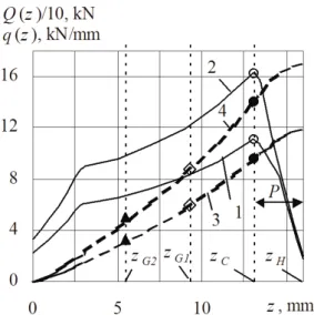
H, where 0zH, are presented in Fig. 2.
In order to estimate a fatigue life until the crack initiation (critical number of loading
cycles N0(z)) in the stud roots, the modified
standard method [24] based on Coffin-Manson-Langer type formula was applied. A
modification elaborated in [20] was performed for a more accurate calculation of the local stresses in the roots of the stud by estimation of the influence of the load distribution along the joint thread.
The validation of the modified method [20] was confirmed through the comparison of the calculation data with the results of the experiments carried out. The data of 294 low fatigue tests of the threaded M16, M20 and M42 joints presented in [20] are applied for these purposes. A magnetic luminescent powder method was used during the experiments to detect the crack initiation in the tested studs. The critical number of cycles indicating the crack initiation is fixed when the length of the macrocrack around
the periphery reaches (3÷6)mm.
It is easy to confirm that the critical values
N0A and N0C as well as the index N0A/N0C
depend on the material properties and symmetry of the loading cycle.
The nature of these relationships is illustrated in Fig. 3. Here, the variation of the
index N0A/N0C against the relative stud
nominal maximum stress of the stresses
Fig. 2. Variation of thread loads q(z) and Q(z) along the joint threads for various relative nominal stress n,max/Rp0.2: 1 – q1(z) for
n,max/Rp0.2=0.59; 2 – q2(z) for n,max/Rp0.2=0.85;
3 – Q1(z) for n,max/Rp0.2=0.59; 4 – Q2(z) for
n,max/Rp0.2=0.85; o – q(zC); – Q(zC); ◊ –
Q(zG1); ▲ – Q(zG2)
cycle
n,max/Rp0.2for the specified values of
the asymmetry factor r=
n,min/n,max of the external cyclic loading is shown. It is obvious from the graph in Fig. 3 that theoretically the cyclic lifetime of the joints M20×2.5 can be prolonged by more than two times.
The above results illustrate the theoretical limits which could be applied for the preliminary evaluation of the cyclic strength of the threaded joint. A detailed analysis basing on explication of positioning and loading cycles is required; however, to predict the real possibilities to prolong the cyclic lifetime of the joint.
4. Increasing the threaded joint lifetime
Increasing the lifetime of the threaded joint M20×2.5 is considered by applying three positioning models described in Section 2. The cyclic lifetimes are calculated by using methodology [20]. The joint material is insensitive to
non-stationary loading, therefore factor dh=1.
Selected results showing the fatigue life prolongation possibilities for the bolted joint M20×2.5 are presented in Figs. 4 and 5. The graphs in Fig. 4 present variations of
the relative loading cycles Tsum/N0C against
an increased number of positioning periods
u. Here, curves 1 respond to the results of
modelI obtained by expressions (9), curves
2 respond to the results of modelII obtained
by expressions (14) and curves 3 respond to
the results of model III obtained by
expressions (16). Each of the above families of the curves contain results obtained for two relative maximum nominal stresses,
n,max/Rp0.2=0.85 drawn by solid lines and
n,max/Rp0.2=0.59 drawn by dot lines, respectively. Presentation of the results is limited by considering the asymmetric
cyclic loading with r=0.6, which is similar
to the characteristic loads of the threaded joints.
The results confirm that the
restriction-free model I yields the optimal solution
defined by the highest values of the total numbers of the loading cycles. Almost three time prolongation could be expected after
ten periods, u=10. The restrictions requiring
an equality of all the positioning periods
Tj=Teq=const in model II, when j >2 and different critical loading during the first
period T1=N0C reduces efficiency of the
positioning which drops until 2.5 times. An additional requirement on equality of all the
loading periods in model III insignificantly
reduces efficiency.
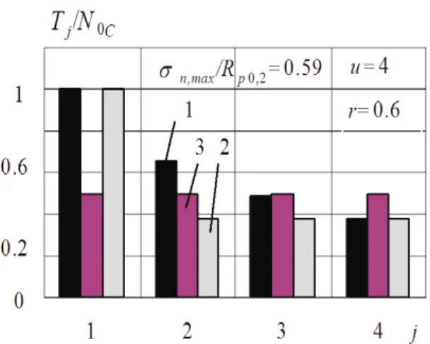
A detailed cycle-by-cycle analysis
obtained by expressions (8), (13) and (15) is illustrated in Fig. 5 by column diagram for
the case of four loading periods (u=4).
Here, the relative durations of the cyclic loading periods are shown. Thereby, each
column contains three sub-columns
reflecting the results obtained by all three positioning models.
Fig. 5 clearly illustrates the influence of restrictions to relative duration of every
loading period Tj/N0C imposed by model II
(T1=N0C and T2=T3=T4=Teq) and model III (T1=T2=T3=T4=Teql) upon comparing these
two models with the restriction-free modelI.
The analysis presented above
demonstrates the real possibility to prolong the overall cyclic lifetime of the threaded joint up 2.5 times
Thereby, the stud cross-sections with cracks after its shifting in depth of the nut still should be sufficiently secure. An analysis of this problem and subsequent discussion are in the following sections.
5. Prediction of the stud’s crack growth in depth of the nut
As shown in Section 2, the stud
cross-section with a crack, formed in the position C
of the threaded joint, is shifted in depth of the nut if the considered method for increasing cyclic strength of the threaded joint is used.
At first in the joint’s section G1 and later in
the sections G2, G3... where considerably
lower axial force Q(z)<Q(zC) acts on the stud core with crack (Fig. 2). Consequently, according to the concept of unloading the cracked stud cross-section, this crack in depth of the nut can be almost frozen i.e. the growth rate of this crack becomes considerably lower in comparison to its growth rate which would be in the risky
section C. It is obvious that the efficiency of
this procedure depends on the crack shifting distance DH.
The purpose of this Section is to verify the efficiency of unloading the stud cracked cross-sections from a fracture mechanics viewpoint.
The loading conditions of the stud crack with it being in the nut depth can be quantitatively characterized by the ratio
Nst(z)/Nst(zC). This ratio makes it possible to
compare the eventual cyclic duration Nst(z)
of the crack stable growth in any stud
cross-section z, located in depth of the nut, with the
eventual cyclic duration Nst(zC), of the crack
stable growth in the stud cross-section which
is located in the risky section C of the nut.
Since resistance of the cracked stud to cyclic loading is mostly predefined by contribution of the stable crack growth, contribution of initial and unstable cyclic cracking stages has been neglected in the below comparison.
Prediction of the stud crack growth with it being in the depth of nut for the considered threaded joints M20×2.5 was performed by applying the same principles which were used to describe its fatigue fracture experienced during the conventional low fatigue tests of 31 specimens [20, 31]. The results of the quantitative prediction of the ratio Nst(z)/Nst(zC) are presented in this Section after clarification of calculation methodology.
The eventual cyclic durations Nst(z) and
Nst(zC) were calculated through the
integration of the well known Paris equation, which relates the stable crack propagation
rate dh/dN with the range of the stresses
intensity factor ΔK1=K1,max-K1,min, where
K1,max and K1,min are the maximum and minimum values of the stress intensity factors of the loading cycle. The Paris equation constants were obtained from the experimental data of 31 conventional fatigue tests of joints M20×2.5, presented in [31], with attention being given to the macrocrack
growth stage in the cross-section zC of the
stud.
In order to calculate the stress intensity
factor K1(z) of the stud stable crack the
formula derived by S. Jarema for the cilindrical rod with crack [32] was used. Having applied this formula the stresses around the crack tip are only determined by the axial force Q(z) which acts in the stud
core. The appropriate turn load q(z) effects
only the shallow (initial) crack and does not influence the stable crack which is deeper.
In the calculations of the eventual cyclic duration Nst(z) the stable crack limit depth
hcr(z) for any stud’s cross-section have been
defined by using conditions of the validity of
the linear fracture mechanics [33]. It was assumed that unstable cyclic cracking occurs
when crack depth overrun limit depth hcr(z).
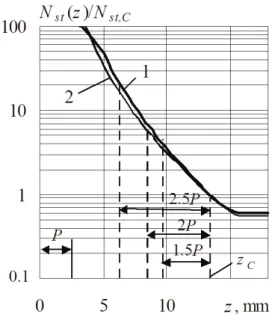
The calculation results for the prediction of the ratio Nst(z)/Nst(zC), which reflects the efficiency of the stud crack growth, with at it being in the nut depth, are presented in Fig. 6.
Fig. 6 shows that the eventual cyclic durations of the stud (M20×2.5) crack
growth Nst(z) are 4.5, 6 and 18 times greater
than Nst(zC), if this crack grows in the stud cross-sections which are in depth of the nut
and remote from the section C by distances
1.5P, 2P and 2.5P respectively. Every
section of the nut mentioned above can be
considered as position G1(Fig. 1b) where the
stud crack can be put after the first nut shifting.
Fig. 6. Relative duration of the stable growth of stud crack in depth of the nut: 1 – n,max/Rp0.2=0.59 and r=0, 0.3, 0.6; 2 –
It is therefore obvious that the stud crack growth can not be completely frozen in the nut zone P<z<zC but can be considerably prolonged.
6. Relative safety factors for the unloaded stud cracks
According to the procedure intended by the cracks unloading method, the
particular stud cross-sections with
recently formed cracks before loading periods T2, T3,... are shifted in the secure place i.e. in depth of the nut. In this Section, the safety of these stud cross-sections after its shifting are defined from the wiev point of the cyclic strength of the whole stud.
During any loading period Tj, the most
dangerous stud cross-section is the one
located in the risky section C of the joint.
Thereby, it is possible to presume that the cyclic lifetime resource of the cracked stud cross-section located in depth of the nut in this time is far greater than that of the dangerous stud cross-section. Thus, the safety of any cracked and unloaded stud cross-section is defined by a relative safety factor expressed in the following form:
(17)
where is the remaining cyclic
duration of the crack stable growth in the
stud cross-section zGi where the crack
occurs at the begining of the loading period (Tj+ Nst(zC)) is the remaining
cyclic lifetime of the stud cross section zC
at the begining of the same loading period
j, zGi is the length coordinate of the
considered stud cross-sections with crack (i. e. zG1, zG2...).
The lowest value from k2,G1, k3,G1 and
k3,G2 shows which crack is the most
dangerous. If the lowest value of the relative safety factor is unaccepted, the
nut moving distance ΔH must be
increased.
It has been defined by calculations that the lowest value of the relative safety factor for the considered threaded joints
M20×2.5 is k2,G1. This value reflects the
relative safety of the first stud crack at the
second loading period T2.
The dependece of the relative safety
factor k2,G1 on the crack shifting distance
in depth of the nut for the optimal case (model I) is shown in Fig 7. If the crack
formed in the stud cross-section zC is
shifted in depth of the nut by distances
DH=1.5P, DH=2P or DH=2.5P, then the
relative crack safety factor takes values in
the folowing ranges k2,G1=(2.4-3.2),
k2,G1=(4-5.5) or k2,G1=(7-10) respectively.
Fig. 7 shows that in the ranges of the example, the lowest values this factor
have at the loading level
n,max/Rp0.2=0.85
and loading asymmetry r=0.6.
In calculation Standards [24] the required safety factor for the conventional threaded joints with regard to low cycle
lifetime is nN=5. The same value can be
accepted for the first consideration in a viewpoint to the relative safety factor
k2,G1. Fig. 7 shows that in the case when
k2,G1=5 is required, the distance of crack
shifting in the nut depth would be
k N z
T N z
j Gi
Gi
j st C
st( )
( )
,
*
N z
j
st( Gi)
*
DH2.2P.
It is obvious that the conventional safety factor must be used also when the crack unloading method is applied. This reduces calculated values of the loading
periods to nN times i.e. its real durations
are T1/nN, T2/nN, T3/nN...
Thus, the safety of the stud cross-sections which periodically comes in to
position C from the cavity of the
bush-washer is regulated by the safety factor nN
as in the case of the conventional operation of the threaded joint. The safety of the cracked stud cross-sections which periodically occur in depth of the nut are regulated by both the conventional safety
factor nN as well as the related safety
factor kj,Gi.
Thus, the quantitative analysis
presented in this Section demonstrates that cracked stud cross-sections can be sufficiently secured by regulation of the
distance DH of the crack shifting in depth
of the nut.
7. Conclusions
Investigation of the cyclic strength of the axially loaded threaded joints behaviour demonstrates possibility to prolong their fatigue life. In summary of the obtained results, the following conclusions can be drawn:
• Mathematical model describing accumulation of the fatigue damage as well as the crack growth in the roots of the stud thread is suggested. Applications of the model demonstrates that the model allows control safety of the threaded joint through the unloading of cracked sections and how to exploit resources of the threaded joint after opening of the crack without reduction of the safety
• On the basis of the above model the procedural method to increase the lifetime of the threaded joint is elaborated. The method operates by varying the mutual positions of the stud and the nut. It was found that the stud crack growth rate can be noticeably retarded due to its unloading by moving the nut.
• Prolongation of the lifetime of the threaded joint can be theoretically
evaluated by the non-dimensional
prolongation factor defined as a ratio of
Fig. 7. Variation of the crack unloading factor against the crack shifting distance in depth of the nut: 1 –
n,max/Rp0.2=0.59;
2 –
the numbers of loading cycles required to initiate cracks in the roots of unengaged and most dangerous engaged turns of the stud.
• The characterizing of the stud crack growth in the depth of the nut can be done by applying the crack growth indexes
experimentally obtained during
conventional cyclic loading of the threaded joints.
• Comparison of the presented
developments with standard safety
requirements shows that the restriction on the growth of the studs crack recently formed in the risky position is completely fulfilled. It should be noted, however, that the multiple crack initiation in the stud thread is possible. Multiple cracks occur after each of the loading periods and are located in different places of the stud thread.
• Formally, the growth of the crack
in the safety depth of the nut is not prevented, therefore, additional control through applying the relative safety factors is obligatory.
References
[1] M. Horstemeyer, D. Farkas, S. Kim, T. Tang, G. Potirniche, Int. J. of Fatig., 32 (2010) 1473.
[2] H. Mughrabi, Proc. Eng., 2(2010) 3.
[3] B. Pyttel, D. Schwerdt, C. Berger, Int. J. of Fatig., 33 (2011) 49.
[4] Y.Y. Sun, M. Song. J. Min. Metall. Sect. B-Metall., 48 (1) B (2012) 45.
[5] R. Heywood, Designing against fatigue, Chapman and Hall LTD, London (1962) 436.
[6] J. Birger, G Iosilevic, Bolted and flange joints, Mashinostroenie, Moscow (1990) p.365 (in Russ.).
[7] Francis R. Kull, in Handbook (J. Bickford, S. Nassar) Marcel Dekker, Inc., New York (1998) p.699.
[8] E. Witte, P. Pagel, Plant. Eng. 31 (1977), 127-131.
[9] A. Yakushev, R. Mustaev, R. Mavliutov, Increasing of strength and reliability of bolted joints, Mashinostrojenie, Moscow, (1979) p.215 (in Russ.).
[10] M. Bergmann, B. Bruzek, H. Lang, Mater. and Des., 31 (2010) 1438.
[11] E. Patterson, B. Kenny, J. Strain Anal., 21 (1986) 77..
[12] N. Noda, Y. Xiao, M. Kuhara, J. of Solid Mech. and Mater. Eng., (5) 8 (2011) 397.
[13] T. Fukuoka, J. of Press. Vess. Techn., 119 (1997) 1.
[14] P. Honarmandi, J. Zu, K. Behdinan, Mech. Bas. Des. of Struct. and Mach., 33 (2005) 311.
[15] K. Marayama, Bull.Japan
Soc.Mech.Engrs., 17 (1974) 442.
[16] E. Patterson, B. Kenny, J. Strain Anal., 21 (1986) 17.
[17] J. Hobbs, R. Burguete, E. J. of Mech. Des., 125 (2003) 527.
[18] E. Patterson, Fatig. Fract. Eng. Mater. Struct., (13) 1 (1990) 59.
33(2011) 166.
[20] A. Krenevičius, M. Leonavičius, Mechanika. (71) 3 (2008) 5.
[21] A. Krenevičius, K. Vislavičius, J. Selivonec, Mechanika, (50) 6 (2004) 5.
[22] K. Vislavičius, R. Kačianauskas, A. Krenevičius, J. Selivonec, Struct. and Multid. Optim., (44) 4 (2011) 575.
[23] ASME Boiler and Pessure Vessel Code, Sec. III. – Rules for construction of Nuclear Power Plant Components, Div. I., Subsec. NB, 1995, p.87.
[24] The Calculation Standards of Strength for Nuclear Energetic Equipment and Pipeline Systems, Energoatomizdat, Moscow, (1989) p.524 (in Russ.).
[25] M. Daunys, Strength and Fatigue Life under Low Cycle Non-Stationary Loading, Mokslas, Vilnius, (1989) p.256 (in Russ.).
[26] V. Jankovski, J. Atkočiūnas, Mechanika, (1) 17 (2011) 5.
[27] A. Seweryn, A. Buczynski, J. Szusta,. Int. J. of Fatig., 30 (2008) 756.
[28] D. Priadi, R.A.M. Napitupulu, E.S. Siradj J. Min. Metall. Sect. B-Metall. 47 (2) B (2011) 199-209.
[29] M. Miner, J. of Appl. Mech., (67) 12 (1945) 159.
[30] J. Selivonec, A. Krenevičius, Mechanika, (46) 2 (2004) 21.
[31] M. Leonavičius, A. Krenevičius, J. of Constr. Steel Res., The Steel Constr. Inst., Elsevier, 46 (1998), CDROM, paper 339.
[32] S. Jarema, Phys. Chem. Mech. of Mater.,
1 (1970) p.87-89 (in Russ.).