D
ESIGN OF A PRE
-
STRESSED BRIDGE
DECK WITH ULTRA
-
HIGH
PERFORMANCE CONCRETE
R
UIM
ACÁRIOG
OMESV
ALENTEDissertação submetida para satisfação parcial dos requisitos do grau de
MESTRE EM ENGENHARIA CIVIL —ESPECIALIZAÇÃO EM ESTRUTURAS
Orientador: Professor Doutor Pedro Álvares Ribeiro do Carmo Pacheco
Coorientador: Engenheiro Gilberto Castro Alves
Tel. +351-22-508 1901 Fax +351-22-508 1446 [email protected]
Editado por
FACULDADE DE ENGENHARIA DA UNIVERSIDADE DO PORTO Rua Dr. Roberto Frias
4200-465 PORTO Portugal Tel. +351-22-508 1400 Fax +351-22-508 1440 [email protected] http://www.fe.up.pt
Reproduções parciais deste documento serão autorizadas na condição que seja mencionado o Autor e feita referência a Mestrado Integrado em Engenharia Civil - 2016/2017 - Departamento de Engenharia Civil, Faculdade de Engenharia da Universidade do Porto, Porto, Portugal, 2017.
As opiniões e informações incluídas neste documento representam unicamente o ponto de vista do respetivo Autor, não podendo o Editor aceitar qualquer responsabilidade legal ou outra em relação a erros ou omissões que possam existir.
Este documento foi produzido a partir de versão eletrónica fornecida pelo respetivo Autor.
ACKNOWLEDGMENTS
I would like to thank not only who directly helped me to develop this work but also the ones who had an important role in my academic course. I would particularly like to acknowledge:
▪ Professor Pedro Pacheco for his motivational words, timely and experienced advices, and the readiness to answer my questions. I would also like to thank by making possible my attendance on High Tech Concrete Symposium in Maastricht which I will never forget. ▪ Engineer Gilberto Alves for his availability to help me whenever I needed. All our
discussions about issues that arose along work process have enriched me. Finally, I should thank him for his predisposal to let me know about deeper subjects that aroused my interest, and for make understand how important is to face the difficulties by going through them as soon as possible.
▪ Professor Mário Pimentel for receive me to discuss about the particularities of Ultra-High Performance Concrete and also for providing me useful scientific documentation and bibliographic references.
▪ Professor Miguel Castro for introduce me computational programming in the point of view of structural optimization. It is a subject that interests me and which soon or later I will go back to it again.
▪ CSI Portugal technical support for elucidate me about software considerations on creep effects.
▪ My cousin, Daniela Valente, for her readiness to assist me in text revision as well as my friends Luis Tiago Costa and Andreia Cardoso.
RESUMO
Este trabalho inclui duas soluções diferentes resultantes do dimensionamento de um tabuleiro de uma ponte com Betão de Desempenho Ultra-Elevado (UHPC). No primeiro caso (Caso 1) o tabuleiro foi inteiramente dimensionado com UHPC, enquanto no segundo caso (Caso 2) é uma solução mista onde o UHPC é colocado onde surgem maiores esforços e no restante tabuleiro é colocado betão normal. O objetivo prende-se com a avaliação da viabilidade económica e comparar estas duas soluções com o projeto da ponte existente, que é um tabuleiro em viga caixão feito de betão normal pré-esforçado. Adicionalmente, análise modal seguida de análise sísmica são realizadas com o intuito de avaliar possíveis mudanças nos esforços máximos que se instalam na substrutura.
Devido às elevadas propriedades mecânicas do UHPC, espera-se que a massa da superestrutura possa ser reduzida. Contudo, com um material de características soberbas vem um custo elevado que pode comprometer a viabilidade económica das soluções em estudo. Por essa razão, o estudo deve ser realizado para que seja avaliado se o dimensionamento com UHPC em lugar do betão normal conduz a soluções viáveis ou não.
A análise estrutural é executada após a elaboração do modelo de cálculo da ponte no software CSiBridge ter sido feita. Além da análise estrutural no modelo da ponte completa, a análise da construção faseada não linear é também considerada para controlar tensões durante a execução da obra. Esta última análise requere a definição da evolução das propriedades dos materiais ao longo do tempo e do planeamento construtivo. O método de dimensionamento passa por realizar verificações das tensões durante o processo construtivo e verificações do estado limite de serviço e do estado limite último durante o período de serviço da estrutura. O dimensionamento dos elementos de UHPC é apoiado por uma norma adequada, NF P18-710, e por uma ferramenta numérica propositadamente desenvolvida para realizar análise da secção transversal durante o dimensionamento ou verificação a flexão e ao corte em estado limite último. Finalmente, para que a solução final da secção transversal seja validada, são realizadas análises de estabilidade quer durante a construção, quer durante a fase em que a estrutura se encontra em serviço para que seja avaliado se o estado limite último é condicionado pela instabilidade ou pela capacidade resistente do material.
É alcançada uma redução da massa da superestrutura na ordem dos 36% para a o Caso 1 e 26 % para o Caso 2, e a quantidade de cordões de pré-esforço é também reduzida para 36% e 32%, respetivamente. Ao contrário do que era esperado, a ação sísmica na direção do alinhamento do tabuleiro não muda nos dois casos, mas na direção transversal o corte basal reduziu cerca de 14.6% para o Caso 1 e 8% para o Caso 2. Existe grande variedade de preço para o UHPC mas não foi encontrada nenhuma solução economicamente viável em ambas as soluções alcançadas. Contudo, é necessário continuar o estudo no sentido da otimização estrutural e quantificação das armaduras.
PALAVRAS-CHAVE:Dimensionamento estrutural, Betão de Desempenho Ultra-Elevado, Ponte, Cimbre Auto lançável, Viga Caixão.
ABSTRACT
A bridge deck is designed with two different solutions where is used Ultra-High Performance Concrete (UHPC) as structural element. The first Case 1, involves a deck thoroughly using UHPC. And the second, Case 2, is a mixed solution with UHPC being placed where the internal forces are higher and the remaining deck is casted with regular concrete. The purpose of this study is to assess the economic feasibility and compare those solutions with the existing bridge which is a multi-span box girder deck made of regular pre-stressed concrete. Additionally, modal analysis preceded by seismic analysis are performed to evaluate eventual changes that may occur on substructure internal forces.
Due to high mechanical properties of this material, it is expected a superstructure with less material. However, with a superb material comes a high cost which may comprise economic feasibility. For that reason, the study must be go forward in order to assess whether the application of UHPC in turn of regular concrete leads to a feasible solution or not.
The structural analysis is executed after the development of bridge numerical model on the software CSiBridge have been done. Besides the analysis on bridge integral model, nonlinear staged construction analysis is also considered to control stresses during execution. This last analysis requires the definition of time dependent properties of the materials and of constructive schedule. The method of design goes through stress verifications during constructive stage, serviceability limit state and ultimate limit state verifications during service stage. The design of UHPC elements is aided by proper design code, NF P18-710, and by a numerical tool purposely developed to perform sectional calculations on both flexural and shear design or verifications in ultimate limit state. Finally, to validate the final solution for the cross-section, buckling analysis is performed in both service and constructive stages to assess if the ultimate limit state is governed by instability issues or by material strength.
It is achieved a reduction on superstructure mass of 36% for Case 1 and 26% for Case 2 and the amount of pre-stress tendons is also reduced to 36% and 32%, respectively. On the contrary to expected, seismic action along superstructure alignment does not change in both cases, but in transverse direction the global base reaction decreased about 14.6% for Case 1 and 8% for Case 2. There is high scatter about the UHPC cost but no economic feasibility was found on both solutions achieved. However, a deeper study on it is required regarding structural optimization and also the quantification of steel reinforcement.
KEYWORDS:Ultra-High Performance Concrete, Movable Scaffolding System, Box Girder, Structural design.
TABLE OF CONTENTS ACKNOWLEDGEMENTS ... i RESUMO ... iii ABSTRACT ... v
1. Introduction
... 1 1.1. PREFACE ... 1 1.2. OBJECTIVES ... 12. State of the art ... 3
2.1.HISTORICAL OVERVIEW ... 3
2.2.BRIDGES MADE OF UHPC ... 5
2.2.1.FOREWORD ... 5
2.2.2. Footbridges ... 5
2.2.3. Road bridges ... 6
2.3.SUMMARY ... 8
3. UHPC as a structural material ... 11
3.1. COMPOSITION ... 11 3.1.1. CEMENT ... 11 3.1.2. AGGREGATE ... 11 3.1.3. SILICA FUME ... 11 3.1.4. SUPERPLASTICIZER ... 12 3.1.5. STEEL FIBERS ... 12 3.1.6. PROPORTIONS... 12 3.2. FRESH STATE ... 13 3.2.1. MIXING ... 13 3.2.2. PLACING ... 13
3.2.3. CURING AND HARDENING ... 14
3.3.HARDENED STATE ... 15
3.3.1.MECHANICAL PROPERTIES ... 15
3.3.1.2. Behavior in tension ... 16
3.3.1.3. Shrinkage ... 17
3.3.1.4. Creep ... 17
3.3.1.5. Other mechanical properties ... 17
3.3.2.DURABILITY ... 17 3.4.AFFORDABILITY ... 18
4. UHPC standards
... 19 4.1. AUSTRALIA ... 19 4.2. JAPAN ... 20 4.3. SWITZERLAND ... 21 4.4. FRANCE ... 22 4.4.1. RECOMMENDATIONS ... 22 4.4.2. STANDARDS ... 22 4.5. SUMMARY ... 235. Pre-stress ... 25
5.1. TECHNIQUES ... 25 5.2. INTERNAL VS.EXTERNAL ... 255.2.1. TENDON LAY-OUT ... 25
5.2.2. EQUIVALENT LOADS ... 26
5.2.3. COMPATIBILITY ... 27
5.2.4. LOSSES ... 28
5.2.5. PARTICULARITIES OF EXTERNAL PRE-STRESSING ... 28
6. Constructive methods
... 296.1. FOREWORD ... 29
6.2. BALANCED CANTILEVER METHOD ... 29
6.2.1. DESCRIPTION AND EQUIPMENT ... 29
6.2.2. IMPACT ON INTERNAL FORCES ... 30
6.3. INCREMENTAL LAUNCHING METHOD ... 31
6.3.1. DESCRIPTION AND EQUIPMENT ... 31
6.4. MOVABLE SCAFFOLDING SYSTEM ... 32
6.4.1. DESCRIPTION AND EQUIPMENT ... 32
6.4.2. IMPACT ON INTERNAL FORCES ... 35
7. Design principles and assumptions
... 377.1. FOREWORD ... 37
7.2. MATERIAL... 37
7.2.1. MECHANICAL PROPERTIES ... 37
7.2.2. CONSTITUTIVE LAW FOR DESIGN ... 38
7.2.3. TIME DEPENDENT PROPERTIES ... 40
7.3. ULTIMATE LIMIT CAPACITY ... 41
7.3.1. BENDING ... 41
7.3.2. SHEAR ... 42
7.3.3. CALCULATION TOOL ... 44
7.3.4. SHEAR AND TRANSVERSE BENDING ... 44
8. Case study: Río Cabriel Bridge ... 47
8.1. DESCRIPTION AND GEOMETRY ... 47
8.2. LOAD CASES ... 50
8.2.1. STAGED CONSTRUCTION ... 50
8.2.2. PERMANENT LOADS (GK) ... 50
8.2.3. TRAFFIC LOADS (TS AND UDL) ... 51
8.2.4. THERMAL ACTION (TK) ... 53
8.3.LOAD COMBINATIONS AND VERIFICATIONS ... 55
8.3.1. EXECUTION STAGE ... 55 8.3.2. SERVICE STAGE ... 56 8.4.CASE 0 ... 57 8.4.1. OVERVIEW ... 57 8.4.2. PRE-STRESS ... 57 8.4.3. RESULTS... 58 8.5.CASE 1 ... 64 8.5.1. OVERVIEW ... 64
8.5.2. PRE-STRESS ... 65 8.5.3. DESIGN ... 66 8.5.4. RESULTS ... 70 8.6.CASE 2 ... 74 8.6.1. OVERVIEW ... 74 8.6.2. DESIGN ... 74 8.6.3. RESULTS ... 79 8.7.COMPARATIVE ANALYSIS ... 84 8.7.1. SUBSTRUCTURE ... 84 8.7.2. QUANTITIES ... 86 8.7.3. COST ASSESSMENT ... 87
9. Conclusion
... 91 9.1. DISCUSSION ... 919.2. RECOMMENDATIONS FOR FUTURE RESEARCH ... 92
REFERENCES ... 95
INDEX OF FIGURES
Fig.2.1 - The Sherbrooke Footbridge in Sherbrooke, Quebec, spans 60 m across the Magog River
with a precast truss made of reactive powder concrete ... 5
Fig.2.2. - Seon Yu Footbridge: a) Arch; b) Cross-section ... 6
Fig.2.3. - General view of Sakata-Mirai Footbridge ... 6
Fig.2.4. - General view of one of the Bourg-Les-Valence Bridges, France, 2001 ... 6
Fig.2.5. - Standard cross-section of Bourg-Les-Valence Bridges, France, 2001 ... 7
Fig.2.6. - Elevation of the Pont de la Chabotte ... 7
Fig.2.7. - The Wapello County Mars Hill Bridge ... 7
Fig.2.8. - Elevation view of Batu 6 Bridge ... 8
Fig.2.9. - Detail of UHPC box girder of Batu 6 Bridge ... 8
Fig.2.10. - Typical section view of Sungai Nerok Bridge ... 8
Fig.3.1. - Examples of treatment for overlaying placement and merging... 14
Fig.3.2. - Typical stress-strain-diagrams of UHPC ... 15
Fig.3.3. - Idealized response of UHPC element subjected to uniaxial tensile force ... 16
Fig.4.1. - Design stress-strain relationship recommended in Design Guidelines for Ductal Pre-Stressed Concrete Beams: in compression (left) and in tension (right) ... 19
Fig.4.2. - JSCE composition of standard mixed ingredients (left) and conditions of standard heat curing (right) ... 20
Fig.4.3. - JSCE Compressive stress-strain curve (left) and tensile stress-strain curve (right) ... 21
Fig.5.1. - Balancing of the dead load in a two-span beam by internal tendons (above) and external tendons (below) ... 26
Fig.5.2. - Equilibrium of an infinitesimal segment of pre-stressing tendon... 26
Fig.5.3. - Equivalent load due to a polygonal tendon ... 27
Fig.6.1. - Balanced cantilever method with provisional scaffolding system ... 30
Fig.6.2. - Balanced cantilever method without provisional scaffolding system ... 30
Fig.6.3. - Dead load internal forces resulting from balanced cantilever method ... 30
Fig.6.4. - Balanced cantilever method - Dead load internal forces redistribution caused by creep ... 31
Fig.6.5. - Effect of the steel nose on internal forces during incremental launching ... 31
Fig.6.6. - Dead load internal forces resulting from incremental launching method ... 32
Fig.6.7. - Dead load internal forces envelope resulting from incremental launching method ... 32
Fig.6.8. - Movable scaffolding system equipment ... 33
Fig.6.9. - Movable scaffolding system equipped with organic pre-stressing system (OPS). ... 33
Fig.6.11. - Positioning of the M70-S during casting works ... 34
Fig.6.12. - Preparing M70-S for launching by opening formwork system ... 35
Fig.6.13. - Preparing M70-S for launching by bringing supports closer ... 35
Fig.6.14. - M70-S reaching the support above the pier of the following span ... 35
Fig.6.15. - Dead load internal forces resulting from construction with movable scaffolding system (MSS) ... 36
Fig.6.16. - Construction with movable scaffolding system – Dead load internal forces redistribution caused by creep ... 36
Fig.7.1. - NF P 18-710 Design stress-strain relationship in compression ... 38
Fig.7.2. - NF P 18-710 Design stress-strain relationship in tension ... 39
Fig.7.3. - Limit strains diagram in ULS for plain UHPC ... 41
Fig.7.4. - Limit strains diagram in ULS for reinforced and/or pre-stressed UHPC ... 41
Fig.7.5. - Analogy between crack width-stress diagram and strain-stress diagram ... 43
Fig.7.6. - Schematic explanation of stress and strain distributions in cross-section ... 44
Fig.8.1. - Río Cabriel Bridge - Plan view ... 47
Fig.8.2. - Río Cabriel Bridge - Elevation view ... 47
Fig.8.3. - Río Cabriel Bridge - Cross-section at mid-span ... 48
Fig.8.4. - Río Cabriel Bridge - Cross-section at above the piers ... 48
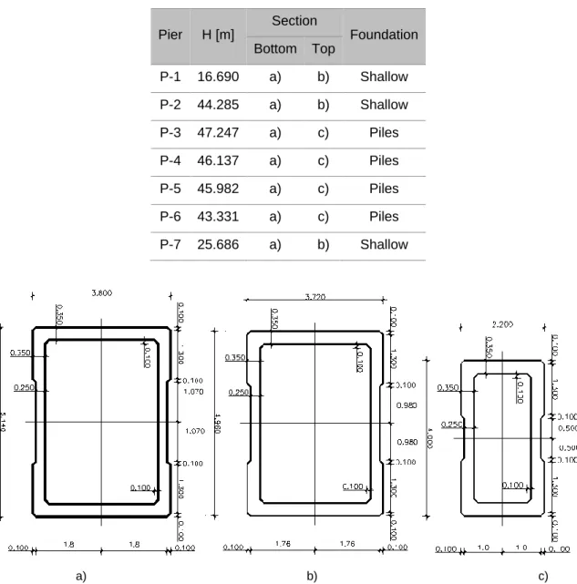
Fig.8.5. - Piers cross-section geometry ... 49
Fig.8.6. - Real pot bearings lay-out ... 49
Fig.8.7. - Equivalent pot bearings lay-out ... 50
Fig.8.8. - Schematic sequence of tasks which represents M70-S loads on structure during a constructive cycle. ... 50
Fig.8.9. - Non-structural elements ... 51
Fig.8.10. - Transverse positioning of the remaining permanent loads (RPL) ... 51
Fig.8.11. - Application of load Model 1 for global (left) and local (right) verifications ... 52
Fig.8.12. - Load model 1: characteristic values ... 52
Fig.8.13. - UDL and TS positioning in order to intensify global internal forces ... 52
Fig.8.14 - Dispersal of TS loads ... 53
Fig.8.15 - Traffic load arrangement for local verifications 1 ... 53
Fig.8.16 - Traffic load arrangement for local verifications 2 ... 53
Fig.8.17 - Traffic load arrangement for local verifications 3 ... 53
Fig.8.18. - Diagrammatical representation of constituent components of a temperature profile ... 54
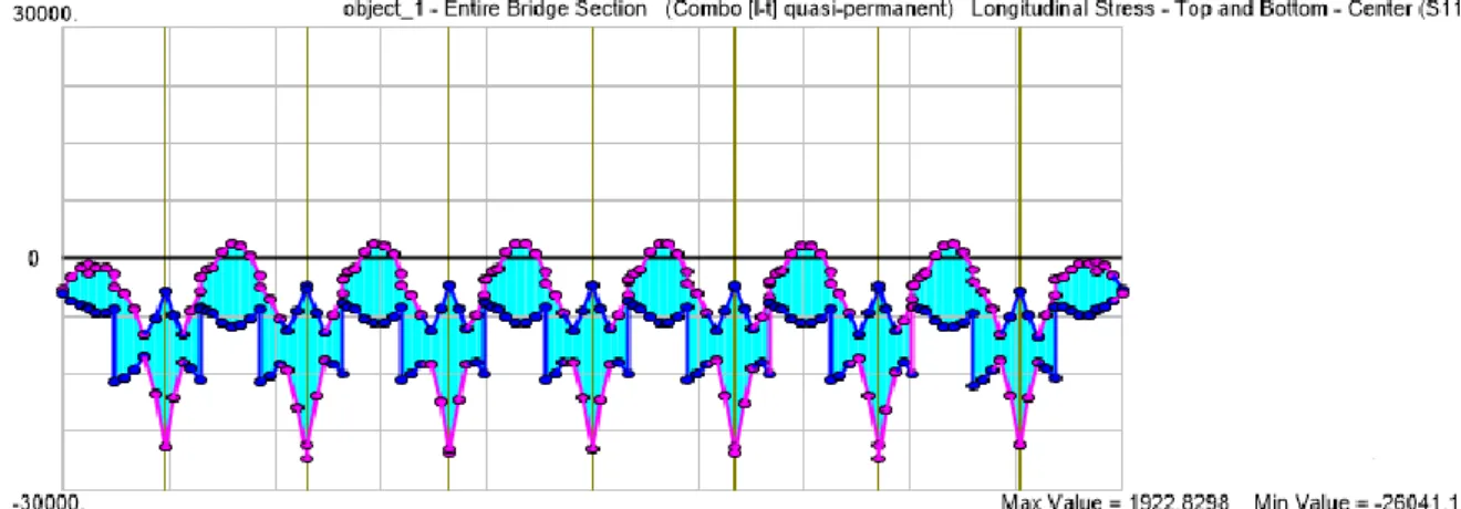
Fig.8.20. - Case 0 - Stresses envelope during constructive process [kPa]. ... 59
Fig.8.21. - Case 0 - Axial force installed in one equivalent tendon after friction losses (P0) and anchorage setting (Pm0). ... 60
Fig.8.22. - Case 0 - Stresses envelope under characteristic load combination [kPa]. ... 60
Fig.8.23. - Case 0 - Stresses envelope under frequent load combination [kPa]. ... 61
Fig.8.24. - Case 0 - Stresses envelope under quasi-permanent load combination [kPa] ... 61
Fig.8.25. - Deformed shape of a representative single span with shell elements under a fundamental load combination. ... 62
Fig.8.26. - Transverse bending moment at mid-span on top slab under a fundamental load combination [kN.m/m]. ... 62
Fig.8.27. - Scheme illustrating where internal forces are measured ... 62
Fig.8.28. - Case 1 - Initial tendons lay-out [m] ... 65
Fig.8.29. - Case 1 - Top slab solution [m]. ... 67
Fig.8.30. - Case 1 - Cross-section solution. ... 68
Fig.8.31. - Case 1 - Stresses envelop during constructive process with a polygonal lay-out of tendons [kPa] ... 69
Fig.8.32. - Case 1 - External tendons lay-out [m] ... 70
Fig.8.33. - Case 1 - Stresses envelope under quasi-permanent load combination [kPa]. ... 71
Fig.8.34. - Case 1 - Stresses envelope under characteristic load combination [kPa] ... 71
Fig.8.35. - Case 1 - Buckling mode during constructive process. ... 73
Fig.8.36. - Case 1 - Buckling mode during service stage. ... 74
Fig.8.37. - Case 2 - Top slab solution [m] ... 74
Fig.8.38. - Case 2 - Longitudinal stresses on bottom fibers during 2nd stage, 1st task of constructive process [kPa] ... 76
Fig.8.39. - Case 2 - Longitudinal stresses on bottom fibers during 2nd stage, 6th task of constructive process [kPa]. ... 76
Fig.8.40. - Case 2 - Material distribution along deck length [m] ... 76
Fig.8.41. - Case 2 - Cross-section solution [m] ... 79
Fig.8.42. - Case 2 - Stresses envelope under quasi-permanent load combination [kPa] ... 81
Fig.8.43. - Case 2 - Stresses envelope under characteristic load combination [kPa] ... 81
Fig.8.44. - Case 2 - Buckling mode during constructive process ... 83
Fig.8.45. - Case 2 - Buckling mode during service stage ... 83
Fig.8.46. - Axis orientation regarding bridge alignment ... 85
Fig.8.47. - Partial costs of scenario 1 ... 88
INDEX OF TABLES
Table 2.1. - Summary of concrete compressive strength developments ... 3
Table 3.1. - Dosages and properties of the most common commercial UHPC ... 13
Table 3.2. - Usual values elasticity modulus, poisson´s ratio, thermal expansion coefficient, and density ... 18
Table 7.1. - Mechanical properties assumed for UHPC during the current study ... 37
Table 7.2. - Values of a-parameter determined by Habel et al. ... 40
Table 7.3. - Assumed values to characterize creep and shrinkage based on the suggestions of NF P18-710 ... 40
Table 8.1. - Characterization of piers’ geometry and foundation ... 49
Table 8.2. - Case0 - Structural materials ... 57
Table 8.3. - Case 0 - Verification of stress limits during constructive process ... 59
Table 8.4. - Case 0 - Local maximum internal forces in the top slab ... 63
Table 8.5 - Case 0 - Average internal forces along in a 2-m cut around the local maximum internal force ... 63
Table 8.6. - Case 0 - Most governing global internal forces under fundamental load combination only containing pre-stressing second order effects ... 63
Table 8.7. - Case 0 - Most governing global internal forces under fundamental load combination containing pre-stressing effects ... 63
Table 8.8. - Case 0 - Bending capacity above the piers ... 64
Table 8.9. - Case 0 - Shear capacity above the pier ... 64
Table 8.10. - Case 0 - Bending capacity at mid-span ... 64
Table 8.11. - Case 1 - Structural materials ... 65
Table 8.12. - Case 1 - First approach to assess minimum slab thickness on Section 1. ... 66
Table 8.13. - Case 1 - First approach to assess minimum slab thickness on Section 2 ... 66
Table 8.14. - Case 1 - First approach to assess minimum slab thickness on Section 3 ... 67
Table 8.15. - Case 1 - First approach to assess minimum web thickness (flexural reinforcement) ... 68
Table 8.16. - Case 1 - First approach to assess minimum web thickness (shear reinforcement) ... 68
Table 8.17. - Case 1 - Assessment of longitudinal reinforcement at mid-span. ... 68
Table 8.18. - Case 1 - Stresses control during constructive stage ... 70
Table 8.19. - Case 1 - Local maximum internal forces in the top slab ... 71
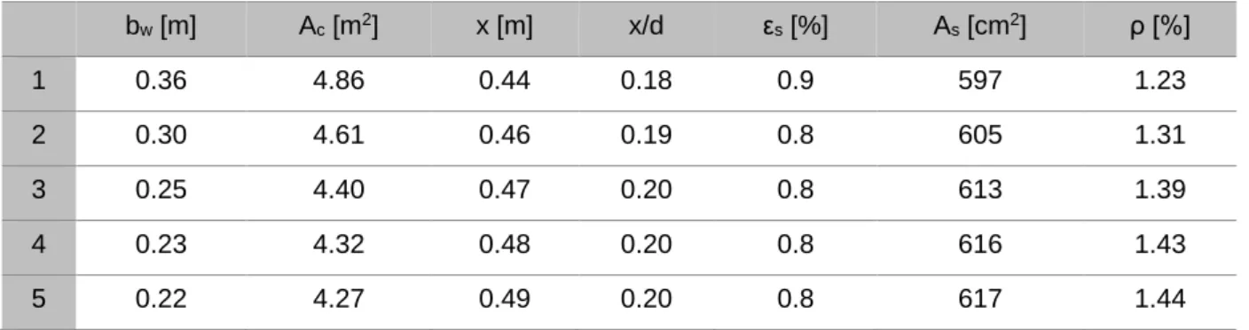
Table 8.20. - Case 1 - Local verification of Section 1... 72
Table 8.21. - Case 1 - Local verification of Section 2... 72
Table 8.23. - Case 1 - Most governing global internal forces under fundamental load combination .... 72
Table 8.24. - Case 1 - Assessment of longitudinal reinforcement at above the piers ... 72
Table 8.25. - Case 1 - Assessment of shear reinforcement above the piers ... 72
Table 8.26. - Case 1 - Assessment of longitudinal reinforcement at mid-span ... 73
Table 8.27. - Case 1 - Assessment of shear reinforcement at mid-span ... 73
Table 8.28. - Case 2 - Structural materials ... 74
Table 8.29. - Bending and shear capacity of Section 1 ... 75
Table 8.30. - Bending and shear capacity of Section 2. ... 75
Table 8.31. - Bending and shear capacity of Section 3. ... 75
Table 8.32. - Case 2 - Most governing global internal forces under fundamental load combination .... 77
Table 8.33. - Case 2 - First approach to assess minimum web thickness (flexural reinforcement) ... 77
Table 8.34. - Case 2 - First approach to assess minimum web thickness (shear reinforcement) ... 77
Table 8.35. - Case 2 - Bending capacity in the left constructive joint. ... 78
Table 8.36. - Case 2 - Shear capacity in the left constructive joint ... 78
Table 8.37. - Case 2 - Bending capacity at mid-span ... 78
Table 8.38. - Case 2 - Shear capacity at mid-span ... 78
Table 8.39. - Case 2 - Bending capacity above the piers ... 78
Table 8.40. - Case 2 - Shear capacity at mid-span ... 78
Table 8.41 - Case 2 - Control of compressive stresses control during constructive stage ... 80
Table 8.42. - Case 2 - Control of tensile stresses control during constructive stage ... 80
Table 8.43. - Case 2 - Most governing global internal forces under fundamental load combination .... 81
Table 8.44. - Case 2 - Assessment of longitudinal reinforcement in the right constructive joint. ... 82
Table 8.45. - Case 2 - Assessment of shear reinforcement in the right constructive joint. ... 82
Table 8.46. - Case 2 - Assessment of longitudinal reinforcement in the left constructive joint. ... 82
Table 8.47. - Case 2 - Assessment of shear reinforcement in the left constructive joint. ... 82
Table 8.48. - Case 2 - Assessment of longitudinal reinforcement at mid-span ... 82
Table 8.49. - Case 2 - Assessment of shear reinforcement at mid-span ... 82
Table 8.50. - Case 2 - Assessment of longitudinal reinforcement above the piers. ... 83
Table 8.51. - Case 2 - Assessment of shear reinforcement above the piers. ... 83
Table 8.52. - Variation of axial force at piers base when compared with Case 0. ... 84
Table 8.53. - Variation of global base reactions when compared with Case 0 ... 85
Table 8.54 - Variation of piers base reactions from Case 0 to Case 1 ... 86
Table 8.56. - Amount of concrete and/or UHPC ... 87
Table 8.57. - Amount of pre-stressing steel ... 87
Table 8.58. - Total cost. ... 88
Table 8.59. - Variation of total cost when compared with Case 0. ... 88
Table 8.60. - Quantity of steel reinforcement allowed, per case, to match the total cost of existing bridge deck. ... 89
SYMBOLS,ACRONYMS AND ABBREVIATIONS
Ac - Area of concrete cross-section Afv - Area of fiber effect
Ak - Area enclosed by the center-lines of the connecting walls, including inner hollow areas Ap - Area of pre-stressing steel
As - Area of steel reinforcement b(i) - Width of layer i
bw - Web thickness
bw,nom - Web thickness deducted by ducts d - Effective depth
Ecm - Mean Elasticity Modulus
Es - Elasticity modulus of steel reinforcement F(i) - Resultant force on layer i
fcd - Design value of concrete compressive strength fck - Characteristic compressive strength
fcm - Mean compressive strength
fctf1%,k - Characteristic post-cracking stress corresponding to a crack width of 0.01H fctf1%,u - Ultimate post-cracking stress corresponding to a crack width of 0.01H fctfk - Characteristic maximal post-cracking stress
fctfk,u - Ultimate maximal post-cracking stress fctfm - Mean maximal post- cracking stress
fctk,el - Characteristic limit of elasticity under tension fctm,el - Mean limit of elasticity under tension
fp0.1k - Characteristic 0,1% proof-stress of pre-stressing steel fpk - Characteristic tensile strength of pre-stressing steel Fs - Total force installed on steel reinforcement
Fs,corrected - Corrected force of steel reinforcement
Fs,correction - Force deducted from UHPC because of steel reinforcement presence fywd - Yield stress of steel reinforcement
H - Depth of the tested prism with dimensions complying with the structures dimensions h0 - Notional size of the cross-section
K - Fiber orientation factor
Lc - Characteristic length used to calculate equivalent strain from the crack width Lf - Fibers length
nducts - Number of ducts on the same horizontal plan Ned - Design axial force
Pmax - Maximum force applied to the tendon r - Degree of reaction
RH - Relative Humidity t - Equivalent time
t0 - Age of the concrete which is subjected to permanent load Ted - Design value of longitudinal torsion force
ts - Age of the concrete at the beginning of drying shrinkage Ved - Design value of longitudinal shear force
Ved,i,t - Design value of shear force in one wall due to longitudinal torsion force Ved,i,tot - Total design value of shear force in one wall
Ved,i,v - Design value of shear force in one wall due to shear longitudinal force Vrd,c - Contribution to shear resistance brought by the concrete matrix
Vrd,f - Contribution to shear resistance brought by the fibers Vrd,max - Resistance of the concrete compressive struts
Vrd,s - Contribution to shear resistance brought by the vertical shear reinforcement w - Crack width
w1% - Crack width of 0.01H
wpic - Crack width corresponding to local peak in post-cracking phase or to a crack width equal to 0.3 mm if there is no peak
x - neutral axis depth or height of the compression zone xi - Position of Layer i
z - Lever arm of internal forces
zi - Lever arm of internal forces in one wall
α - Shear reinforcement inclination angle
αcc - Coefficient that takes into account the long-term effects on the compressive strength ε(i) - Strain of the layer i
εc0d - Design value of maximum compressive elastic strain εca - Autogenous shrinkage strain
εcd - Drying shrinkage strain εcs - Total shrinkage strain
εcud - Design value of ultimate compressive strain εs - Steel reinforcement strain
εsyd - Yield strain of steel reinforcement εu - Ultimate tensile strain in the extreme fiber εu,el - Elastic tensile strain at ULS
“εu,el” - Truncated elastic tensile strain at ULS
εu,lim - Ultimate strain beyond which fibers participation is no longer taken into account at ULS
εu,pic - Ultimate equivalent strain corresponding to the local peak in post-cracking phase or to a crack width equal to 0.3 mm if there is no peak
εu,1% - Ultimate equivalent strain corresponding to a crack width of 0.01H θ - Strut inclination angle
ν - Poisson's ratio ρ - Reinforcement ratio σ(i) - Stress installed on layer i σc - Stress installed on concrete σcp - Average cross-section stress
σf(w) - Stress law as a function of crack width σp,max - Maximum stress applied to the tendon
σpm0 - stress in the tendon immediately after tensioning or transfer σRd,f - Residual strength of the fiber-reinforced cross-section σs - Steel reinforcement stress
σt,averege - Average stress along the crack ϒc - Partial factor on compression ϒcf - Partial safety factor on fibers
φ - Curvature
φb - Basic creep coefficient φd - Drying creep coefficient Φducts - Ducts diameter
AFGC - Association Française de Génie Civil CC - Conventional Concrete
EC2 - Eurocode 2
FHWA - Federal Highway Administration JSCE - Japan Society of Civil Engineers LMSS - Large Movable Scaffolding System MDF - Micro-Defected-Free
MSS - Movable Scaffolding System OPS - Organic Pre-Stressing System PS - Pre-stressing
RCP - Reactive Powder Concrete SLS - Serviceability limit state TS - Tandem System
UDL - Uniformed Distributed Load ULS - Ultimate limit state
US - United States W/B - Water-Binder ratio W/C - Water-Cement ratio
Eq. - Equation Fig. - Figure
1
INTRODUCTION
1.1. PREFACE
History have been showed us that structural form is closely interrelated with the material of which it is made of. For this reason, when some new material emerges new structural geometries may also appear so that the material properties can be fully exploited. Arches were early built with stone and then steel brought other structural geometries as trusses, suspension and tied bridges. Consequently, and as already have been proven, UHPC will also provide structural designers with superb mechanical properties to develop new structural concepts.
With the increasing mobility and accessibility needs comes a growing demand on infrastructures like bridges either in quantity or load bearing capacity. Consequently, the search for economical solutions is indispensable. The emergence of a new material such as UHPC, which is characterized by its compressive strength higher than 150MPa and tensile strength provided by steel fibers around 10MPa, certainly leads to lighter structures once that there is required less material to resist the same loading. However, a major hindrance emerges and which is related with material high cost. Therefore, to evaluate whether UHPC application is economical or not, studies on that should be performed.
This study bases in a real project of an existing multi-span continuous bridge whose cross-section is re-designed with UHPC material. A pair of different solutions are proposed, designed and then compared with the initial and existing solution. In the first case, the bridge deck is thoroughly designed with UHPC and, in the second case, it is designed with a mixed solution of conventional concrete (CC) and UHPC.
Even before reaching design phase, there was a need of studying and understanding several matters without which it would be impossible to go forward. It starts by a deeper understanding on material properties and composition. Then, a review over existing codes and guidelines referred to UHPC structural design allowed making a reasonable choice on what would be the proper document to follow during design. The differences between internal and external tendons are described so that can support design and modeling procedures as well as the constructive method and its implications on structural analysis and design.
1.2. OBJECTIVES
The focus of this study is on the design of a bridge deck with UHPC. In order to accomplish that, it is necessary to go through the following works:
▪ Identify existing design standards; ▪ Study of the constructive process; ▪ Load characterization;
▪ Develop numerical structural models in the software CSiBridge; ▪ Comparative analysis.
2
STATE OF THE ART
2.1. HISTORICAL OVERVIEW
Several experiments and studies were carried out aiming to increase concrete strength. Most developments occurred during two decades between 1970’s and mid-1990’s. In Table 1.1. is shown a brief chronological explanation of most significate advances during that period.
Table 2.1. - Summary of concrete compressive strength developments
Source fcm [MPa] Name Conditions/Technics
Roy, Gouda and Bobrowsky
(USA, 1972) [20]
510 -
▪ Only cement paste with high heat treatment (250ºC) and high-pressure treatment (50MPa).
Yudenfreund, Odler and Brunauer (USA,
1972) [21]
240 -
▪ Only cement paste with very thin clinkers (Blaine surface areas ranging from 6000 to 9000cm2/g);
▪ Low water-cement ratio (0.2-0.3); ▪ Use of additives to increase workability; ▪ Vacuum mixing to reduce air entrainment. Birchall, Howard and Kendall (UK, 1981) [22] 200 Micro-Defected-Free (MDF) Paste
▪ Only cement paste;
▪ Removal of large voids on cement undetected by conventional methods. Bache (Denmark, 1981) [23] Up to 270 High-Strength Densified with small particles (DSPs) Concrete
▪ Mortar made of sand (up to 4mm);
▪ Densely packed cement with ultra-fine particles arranged in the space between the cement; ▪ Heat treatment during cure (80ºC);
▪ Extremely low water content (0.13-0.18 by weight of cement and ultra-fine particles); ▪ Large quantity of superplasticizer. Richard and Cheyrezy (France, 1995) [24] Up to 810 Reactive Powder Concrete (RPC)
▪ Excluding coarse aggregate;
▪ Heating (250-400ºC) and pressure (50MPa) treatments;
Two major lines of research have been followed aimed to achieve high mechanical performance with cementitious matrix materials. The first concerns high-strength DSPs concrete, with high superplasticizer and silica fume content, also incorporating ultra-hard aggregate [23]. Another approach was oriented towards improving the strength of the paste, based on the concept of the so called MDF [22].
But high-strength DSPs concrete was developed further by Scientific Division of Bouygues [24]. This research considered not only different aggregates and steel fiber lengths but also different curing treatments. In one of their tests neither pressuring treatment nor heat-treatment was applied (20ºC) which can be compared to field cast conditions. Steel straight fibers were added to the cementitious material matrix (2-2.5% per volume) and compressive strength reached 170MPa. Moreover, it was concluded that steel fibers enhanced ductile behavior on rupture. With the Lafarge cooperation, a new mix formulation was developed and called of “Reactive Powder Concrete” (RCP) which continues to exist in the commercial form of “Ductal” [25].
RCP is a branch of UHPC family whose maximum grain sizes is approximately 0.8 mm whereas it generally may reach approximately 5.0mm [26]. In section Proportions where different mix formulations are presented, that particularity can be verified.
Since then, this material was the starting point for researchers and engineers who have begun extensive investigation studies. The objective was to improve and characterize even better its behavior. Only this way would be possible to industrialize it and provide engineers with technical normalization to apply it in design and construction.
After UHPC have become commercially available in the United States in 2000, the Federal Highway Administration (FHWA) started to investigate its use in highway infrastructure in 2001. FHWA along with State Transportation Department have worked to deploy the technology since 2002. Simultaneously, several universities were doing research work on UHPC. All of this led engineers to apply this material in bridges in many ways. The most common usage was in bridge joints but in 2006 the first highway bridge was constructed in the US [27].
In 2002, France came with the first design recommendation on UHPC. This document results from multiple checks and tests carried out during the development of nuclear-power-plant cooling towers and Bourg-lès-Valence bridges [28]. It addresses mechanical characteristics, structural design methods and durability of UHPC [29]. Consequently, several bridges have been built in France since then. As design standards were missing elsewhere, this recommendation had been also used out of France [25]. Later in 2013 this recommendation was updated mainly motivated by compatibility with entering in force of Eurocodes [30] and, in 2016, a French national annex to EC2 arose.
Since 2004, International Symposium on Ultra-High Performance Concrete have taken place in Kassel (Germany) every 4 years. But later in 2012, the international symposium extended its focus towards nanotechnology in construction materials. A 12-million-euros Research Program on UHPC was launched by German Research Foundation. It begun in 2005 with the contribute of more than 20 institutes to investigate about 40 projects. In the end (2012), the research results were supposed to provide a strong basis to develop reliable technical standards. The goal was to enable industries to produce reliable UHPC using regionally available raw materials and provide engineers with guidelines to design proper structures [27].
Other Asian countries have shown interest in this material too. Japan’s first guideline appeared in 2004 which represents a modified version of the French recommendations [16]. Korea Institute of Construction Technology launched a 6 years’ research program (Super Bridge 200) started in 2007 to
investigate the use of UHPC in cable-stayed bridges. The total budget was about 10 million euros [31]. Bridge construction cases on these countries are as well referred in Bridges made of UHPC chapter. In Malaysia, UHPC has been used as a sustainable way of construct bridges and, in 2014, it had already been built 24 bridges with this material [32].
According to State-of-The-Art Report of FHWA [27] there are several countries spread all over the globe which adopted UHPC as main structural material for bridge construction. It shows, therefore, that UHPC potentials are being recognized and receiving worldwide attention.
2.2. BRIDGES MADE OF UHPC
2.2.1.FOREWORD
The report made by U.S. Department of Transportation, that approaches the UHPC state of the art [27], lists several bridges where this material had been applied before 2013. This list covers North America, Europe, Asia, and Australia. Some cases, UHPC is used on local repairs, or wet joints or even connecting adjacent precast beams. Other cases it is applied as the main structural element and is about this last case the following examples are referred to.
2.2.1.FOOTBRIDGES
Footbridges are interesting structures in the point of view of UHPC potential. That is justified by architectural requirements, for instance visual lightness. The material higher strength allows the design of slender structures. Herein are mentioned some remarkable UHPC footbridges and their main features.
The first UHPC bridge is located at Sherbrooke in Canada in 1997. It is a pre-stressed pedestrian/bikeway bridge (Fig.2.1.) made of six precast segments each 10m long and spanning a total of 60m long. The precast segments are open-web space trusses without conventional steel reinforcement. Upper and lower chord members are made from UHPC with 200MPa compressive strength. The top chord is materialized with a ribbed slab with 30mm thickness, and transverse pre-stressing was applied with sheathed monostrands. The bottom chord is made of two pre-stressed beams. In the web diagonal members, UHPC is confined in stainless steel tubes. Finally, the precast segments are assembled with external pre-stressing tendons [19].
Fig.2.1 - The Sherbrooke Footbridge in Sherbrooke, Quebec, spans 60 m across the Magog River with a precast truss made of reactive powder concrete [1, 19].
The Seon Yu Footbridge (2001) was erected in Seoul, South Korea, with 430m of total length (Fig.2.2.). To allow pedestrians crossing the Han River, the structure is composed by an arch which accomplishes 120m span. It consists of six precast elements with double-T (or π-shape) cross-section
supporting a UHPC ribbed slab [18]. Due to UHPC mechanical properties, it was possible to design a very slender arch with thin sections, resulting in a lighter perception.
Fig.2.2. - Seon Yu Footbridge: a) Arch [1]; b) Cross-section [18].
Other structures, with the same function but with different forms, have been built since then in many countries. For instance, the Sakata-Mirai footbridge (Fig.2.3.) was built in 2002 and it was the beginning of bridge design using UHPC in Japan. It is a post-tensioned box girder structure with perforated webs. The self-weight of the deck resulted in about 25% of that of ordinary pre-stressed concrete bridge. The deck is also constituted with 6 precast segments that when combined with external pre-stressing it achieves 50m span length [33].
Fig.2.3. - General view of Sakata-Mirai Footbridge [1]
2.2.3. ROAD BRIDGES
The Bourg-Les-Valence Bridges (Fig.2.4.) are known to be the two first UHPC road bridge applications. They have two 20-m-long-spans each constructed by mean of π-shaped pre-stressed beams without any passive reinforcement (Fig.2.5.). These spans are statically determinate and the joint connecting longitudinal beams was made in situ using internal reinforcement and UHPC too [7].
Fig.2.5. - Standard cross-section of Bourg-Les-Valence Bridges, France, 2001 [7].
Still in France, a single span bridge with 47.40m of length was constructed during 2004. Its name is Pont de la Chabotte (Fig.2.6.) and it comprises 22 glued segments with some of them having different geometry to anchorage external pre-stressing tendons. The depth of the cross-section is 1.6m and the upper slab width is 4.4m. So, this bridge slenderness is characterized by span-to-depth ratio of 30. The webs and the lower slab have a constant thickness of 0.12m whereas the upper slab has 0.14m. When compared with an eventual conventional C35/45 concrete solution, this bridge only needs 40% of that concrete volume and 1/3 of that assembling duration. Furthermore, this box girder bridge is free of longitudinal passive reinforcement [11].
Fig.2.1. - Elevation of the Pont de la Chabotte. [11].
The construction of first highway bridge in the US making use of UHPC dates to 2006 (Iowa, USA) and it is called The Wapello County Mars Hill Bridge (Fig.2.6.). It comprises three 33.5m long precast UHPC beams with bulb-tee cross-section form. Each beam is pre-stressed and there is no need of shear reinforcement. All together support a cast-in-place bridge deck [14].
Fig.2.2. - The Wapello County Mars Hill Bridge [14].
Malaysia have been adopted UHPC has a mainstream material for bridge construction. It is there that the world’s longest single span road bridge was constructed. Batu 6 Bridge (Fig.2.7.) is constructed with precast segments of 4 m high, 2.5m long and 5m wide. The typical mid-span section has very slender elements (Fig.2.8.) but the webs are locally thickened to accommodate the shear keys and the bottom slab at the ends is also thickened to accommodate anchorages. There is no passive
reinforcement to stand ultimate bending moment forces. However, it is uniquely used as anti-bursting reinforcement in the anchorages and to transfer longitudinal shear between webs and upper slab [34].
Fig.2.3. - Elevation view of Batu 6 Bridge [34].
Fig.2.4. - Detail of UHPC box girder of Batu 6 Bridge [mm] [34].
One last existing example is given. Sungai Nerok Bridge is another bridge in Malaysia with integral beam-deck system (Fig.2.9.). This multi-span, continuous road bridge has a total width of 15m and three spans of 30 m each, creating a total bridge length of 90m. The structural component cost was USD906/m2 which is lower than the homologous value of CC bridges in Malaysia, USD1.100 to USD1.400/m2. The immediate cost saving s amounts 17% even knowing that durability may increase that value at long-term.
Fig.2.5. - Typical section view of Sungai Nerok Bridge [mm] [32].
2.3. SUMMARY
In the last 5 decades have been published works that show the interest in enhancing concrete overall performance mainly its maximum compressive strength. The material formulation has been changed until mid-90’s. Since then the formulation have remained practically unchanged and studies started to
focus in the characterization of mechanical properties. There are 3 work fronts which have an interdependent relationship between each other. They are researching, standard development, and real structures applications. Most of the continents have been doing that resulting in UHPC bridges all over the world.
All the bridges introduced are examples of how bridges have been designed with UHPC. Most of the times bridge elements are pre-cast and then assembled at their final position which is justified by the high controlled conditions during material production. With UHPC is possible to design slender and lighter solutions and, in some particular cases, it may compete against CC structures regarding immediate costs.
3
UHPC AS A STRUCTURAL
MATERIAL
3.1. COMPOSITION
3.1.1. CEMENT
UHPC mixtures usually are designed of ordinary Portland cement (generally combined with silica fume). As result of dense packing, a very low water-cement ratio is achieved. Consequently, binder components do not hydrate completely and they will also work as filler [35]. Furthermore, cement selection cannot be dissociated from that of superplasticizer [24].
3.1.2. AGGREGATE
Fine quartz sand aggregate combined is frequently used as this material is readily available, has low cost, is very strong and promotes excellent paste/aggregate interfaces. The most common maximum particle size of sand used in UHPC is limited to over 5 or 6 mm [26, 36]. Both angular or natural sand can be used but is preferred the second one because of lower water requirements [24].
In some cases, quartz powder may be used. It has particle size distribution ranging from 0.1 to 100μm and usually acts like a filler. However, this ultra-fine material is an essential ingredient for heat-treated UHPC whose maximum reactivity is obtained for particle size of between 5 and 25 µm [24].
3.1.3. SILICA FUME
Silica fume is an industrial byproduct and has a typical diameter of 0.2μm. This admixture is usually combined with cement. The implementation of this admixture has three main functions:
▪ Filling the empty space between the cement particles
▪ Improvement of rheological behavior through the lubrication effect resulting from the perfect sphericity of the basis particles
▪ Secondary hydrates resulting from pozzolanic reaction with the calcium hydroxide In order to control impurities, that the Blaine finesses must be limited to 22m2/g. It was also proposed that silica fume content should be about 25% of Portland cement weight. [24].
If heat treatment is applied (80-90°C) there will be formation of additional strength-forming hydrate phases. Contrary, without that treatment the filler effect remains [37].
3.1.4. SUPERPLASTICIZER
It was concluded that a combination of selectively adsorbing polycarboxylate superplasticizers is more effective than individual polymers [38] for dispersion of the cement/silica blend. This chemical admixture is a dispersing agent that allow to reduce water content. But superplasticizers also exhibit a retarding characteristic on cement hydration which can present a problem for practical applications [24].
The main characteristics of the polycarboxylate based superplasticizers are the following: ▪ High water reduction (up to 40%)
▪ High flowability
▪ Polymer-design allows to control the main characteristics (setting time and workability) ▪ Blending of different polymers is possible: formulation of customized solutions
As mentioned previously, cement and superplasticizer cannot be chosen individually. With these main characteristics, it is possible to adapt the superplasticizer to the cement conditions and to achieve a perfect optimization of the cement paste. The binder content of UHPC can be 4 times higher when compared to a CC, which leads to an increased admixture content of up to 15 times. This shows the importance of the choice of the right superplasticizer type. Studies show that big differences occur mainly in setting time and early strength development, whereas the influence on final strength is not significantly influenced [39].
3.1.5. STEEL FIBERS
There are several types of fibers that can be integrated in UHPC mixture. In the current work only steel fibers are used. Depending on fiber content, UHPC attains the following characteristics [26]:
▪ Increase of fracture energy, subsequent improvement of ductility; ▪ Increase of strength (manly tensile strength);
▪ Reduction of tendency for cracking.
In order to enhance ductility in their compressive tests, Richard and Cheyrezy [24] used straight steel fibers with 12mm long and a diameter of 0.15mm.
In Malaysia, several bridges have been constructed using UHPC whose steel fibers are from two different type. One of them is straight with 20mm length and 0.2mm of diameter. And the other type is end-hooked and had dimensions of 25mm length by 0.3mm diameter [32]. Moreover, Japanese Recommendation [40] suggests the use of fibers 10 to 20 mm in length and 0.1 to 0.25 mm in diameter, with a tensile strength of 2000MPa or more and 2% volume fraction.
3.1.6. PROPORTIONS
In CC, water-binder ratio (W/B) is between 0.4 and 0.6. But in UHPC that ratio is reduced to below 0.25 thanks to two major aspects. First, the addition of superplasticizer has a deflocculating effect on binder. And second, thin granulometry is used and which requires higher content of cement. In summary, binder content increases whereas water content remains practically the same. Silica fume amounts about 20% of the cement weight [41].
The very compact UHPC induces not only very high compressive strength but also more pronounced fragile behavior with complete loss of any plastic domain. Steel fibers are added to ensure non-brittle
behavior. It is currently used a fiber content of 2% by volume [24, 32, 41]. Moreover, regulations on UHPC structures indirectly control fibers quantity through a minimum ductility condition [6].
The proportions of UHPC composition may vary among the suppliers and it also depends on raw materials locally available. Some of the few patents in the world market are presented in Table 3.1..
Table 3.1. - Dosages and properties of the most common commercial UHPC. [36]
Element
Ductal® BSI® CEMTECmultiscale® BCV®
Type Kg/m3 Type Kg/m3 Type Kg/m3 Type Kg/m3
Cement Portl. 746 - 1114 CEM I 52.5 1050
2115 (premix) Silica fume - 242 - 169 - 275 Quartz flour - 224 - - - - Sand (mm) 0.1-0.6 1066 0-6 1072 <0.5 730 2-3 Water W/C 0.19 W/C 0.19 W/C 0.181 W/C 0.25
Admixture Chryso 9 SIKA 40 Chryso 35 - 21.5
Fiber (mm) 13/0.2 161 20/0.3 234 10/0.2 470 202/3131/3 156 Slump (mm) 700 640 - 750 Fct,28 (MPa) 8 8.8 - 8 Fcm,7 (MPa) 20º 101 20º 165 20º - 20º 98 Fcm,28 (MPa) 20º/90º 124/198 20º 199 20º 168 20º/90º 130-150 3.2. FRESH STATE 3.2.1. MIXING
Any CC mixer is capable of mix UHPC but it requires more mixing energy when compared to CC, which means that mixing time should be longer. This fact combined with fine grain size and low water-binder ratio may lead to undesirable overheat during mixing. It can be avoided by using a high-energy mixer, or lowering the temperatures of the constituents, or even replacing the mix water with ice [42].
The UHPC production requires long mixing times that depends on the ambient temperature. It easily lasts 12 minutes of mixing time. Thus, it restrains plant production and increases costs significantly. The mixing time of UHPC can be reduced by optimizing the particle size distribution by means of replacement of cement and quartz flour by silica fume, matching the type of superplasticizer and cement in the mix and increasing the speed of mixing [43].
3.2.2. PLACING
Placing operations have a fundamental role on UHPC fibers orientation. Therefore, UHPC ultimate tensile strength and ductile behavior are highly influenced by placement method [41]:
▪ Fiber reinforcement tends to show a preference for aligning in the direction of flow during casting;
▪ The fibers close to the walls tend to be oriented parallel to the formwork. The thinner the element, the greater will be the impact on the tensile strength;
▪ A preferred orientation of fibers in the direction of gravity can sometimes occur due to the natural behavior of fibers in the viscous liquid phase of the UHPC before setting. These phenomena must be considered during development of casting sequence. In an advanced phase of this work it will be explained how fiber scatter and element fineness is considered on design. Internal vibration is not recommended so that fibers orientation don’t be interfered. However, limited external form vibration can be applied in order that entrapped air could be released. Despite that, packing rarely is a problem due to UHPC self-compacting ability. Placement shall be performed using tremie pipes or buckets. Additionally, continuous poring until the completion in one area shall be planned. Overlay placing and merging areas shall be avoided (Fig.3.1.) during casting process because they become weak points [16, 42]. UHPC must be dropped up to 0.50 m and if this indication cannot be satisfied, a test should be done beforehand to ensure that there is no segregation of fibers nor fiber clustering [30].
Fig.3.1. - Examples of treatment for overlaying placement and merging [3]
The French recommendation [30] gives some instructions that should be considered in adverse weather conditions. Concreting is not recommended when the outdoor temperature falls below +5°C. However, special arrangements can be made to overcome this issue allowing proper concreting process:
▪ Heating of aggregate and/or mix water; ▪ Use of thick timber or insulated forms; ▪ Use of setting and hardening accelerators.
High outdoor temperature (>35°C) induces undesirable high temperatures inside thick components during hydration process. The precautions pointed are similar to those which can be adopted for CC for example cooling of mixing water.
3.2.3. CURING AND HARDENING
The reduced water-binder ratio in a UHPC mix necessitates careful attention to prevent water to escape prior to hydration. That is why, right after casting, UHPC surface must be covered with an impermeable layer. When UHPC surface is properly covered, avoiding any space between seal and UHPC, the possibility of surface dehydration is eliminated. That avoids cracking and significant degradation of final material properties [42]. Additionally, the surface of constructive joints should be systematically cured so that surface drying and also micro-cracking during setting may be prevented [30].
Heat (90ºC) and steam (RH=95%) treatment may be applied to UHPC to accelerate hydration and enhance final mechanical properties including durability. These treatments are only feasible in precast plant [42]. When comparing compressive strength of UHPC cured at 90ºC (until 7 days) and 20ºC, it was concluded that without heat treatment the compressive strength decreases (≈20%) whereas compressive ductility increases. The UHPC cured at 20ºC, like in situ curing conditions, could lead to a more economical and sustainable option. Despite of compressive strength reduction, cast-in-place must be considered so that expenses of both high-temperature curing and pre-casting procedures can be avoided [44].
A study on mechanical properties development [45] at 20ºC, demonstrate that hydration reaction starts after 26h after water addition. This period is denominated of “dormant period” which is longer than in CC and that is governed by high amount of superplasticizer in the mix. Mechanical properties started to develop at approximately 32h after water addition. 7 days after, the UHPC compressive strength reached 140MPa (81% of final strength). This high rate of mechanical properties development on early ages may be advantageous to accelerate the construction process. And finally, 90 days after, the development of mechanical properties practically stopped.
3.3. HARDENED STATE
3.3.1. MECHANICAL PROPERTIES
3.3.1.1. Behavior in compression
The typical compressive strength of UHPC is in the range of 150 to 250MPa. UHPC shows a linear elastic behavior until about 70 to 80 % of the ultimate compressive strength. The scatter of compressive strengths tests results is usually low due to homogeneity of the material [41]. The strain at peak stress for UHPC is approximately 4.4 ‰. Thanks to the fibers, a pronounced descending branch can be developed (Fig.3.2.). Its configuration is influenced by the following aspects [8]:
▪ Fiber content; ▪ Fiber orientation; ▪ Fiber geometry;
▪ Fiber stiffness (in case of using different fiber types);
Fig.3.2. - Typical stress-strain-diagrams of UHPC [8].
3.3.1.2. Behavior in tension
Graybeal and Baby [9] characterized uniaxial tensile response of UHPC specimen after a set of direct tension tests (Fig.3.3.). The response can be divided into four phases:
▪ Phase I - Linear elastic domain;
▪ Phase II - Multiple tightly spaced cracks occur in the cementitious matrix whereas fibers are bridging those cracks. The cracks occur sequentially whenever the stress overpass the matrix cracking strength;
▪ Phase III - It occurs crack saturation where additional cracking is unlikely so individual cracks extend;
▪ Phase IV - Individual crack has reached its extension limit and the fibers bridging that crack begin to pull out of the matrix.
Fig.3.3. - Idealized response of UHPC element subjected to uniaxial tensile force [9].
It is important to mention that only was considered strain hardening behavior which is associated with a limited minimum fiber content and appropriate fiber orientation. Otherwise, neither multi-cracking phase would be possible nor the consequent phases. Therefore, a softening post peak behavior would occur subsequently to phase I.
In their experiments, Graybeal and Baby tested UHPC produced in different curing conditions and with different compositions [9]. The mechanical response results of direct tensile test had the fallowing values:
▪ First cracking strength from 6 to 9MPa; ▪ Multi-cracking stress from 7.8 to 11.5MPa; ▪ Maximum tensile stress from 8.5 to 11.5MPa; ▪ Strain at crack saturation from 3 to 5.4‰; ▪ Strain at localization from 3.4 to 6.5‰.
French recommendations [29, 30] identify three different tensile behaviors after cracking for design purpose:
▪ High strain-hardening which the post-cracking peak is higher than elastic resistance because of high fiber content.
▪ Low strain-hardening which corresponds to most of the UHPCs currently on the market. ▪ Strain-softening is characterized by crack localization once the matrix strength is reached,
when a tensile force is applied. This type of constitutive law can be found in UHPCs with a low fiber content or containing fibers that are not very efficient.
Additionally, a new French standard [46] gives expressions to classify post-cracking behavior of a given UHPC material from specific tests results.
3.3.1.3. Shrinkage
The shrinkage of UHPC barely depend on humidity and elements dimensions, because it is primarily influenced by endogenous processes [47]. In the case of a heat treatment during the first few hours, shrinkage partly occurs during heat treatment and 550 µm/m total shrinkage is expected for outdoor environment. In the case of heat treatment after the UHPC has hardened, it is considered that there will be no further shrinkage once the treatment is finished. And finally, if there is no heat treatment, to the 550 µm/m for endogenous shrinkage is added the 150 µm/m for drying shrinkage in an outdoor environment [30].
3.3.1.4. Creep
Like CC, creep is mainly influenced by the age of loading, permanent load magnitude and its duration. Heat treatment at early age before or after UHPC has hardened may significantly stabilize creep effects [47]. Indicative values of the long-term creep for UHPC with heat treatment before or after UHPC has hardened, and UHPC without heat treatment normally round 0.4, 0.2, and 0.8, respectively [30].
3.3.1.5. Other mechanical properties
In the Table 3.2. are summarized indicative or recommended values by different countries for predesign calculations. Those values are referred to elasticity modulus (E), poisson´s ratio (ν), thermal expansion coefficient (α), and density (ρ).
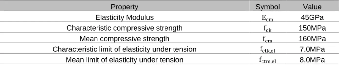
Table 3.2. – Usual values elasticity modulus, poisson´s ratio, thermal expansion coefficient, and density. Country E ν α ρ [GPa] - [10-6 m/m/ºC] [kg/m3] France 45 - 65 0.2 11 2200 - 2800 Japan 50 0.2 13.5 - Switzerland 45 - 65 0.2 10 - Australia 50 0.2 - 2400 - 2650 3.3.2. DURABILITY
It has been mentioned that UHPC is very homogeneous concrete thanks to its high packing density and its ultrafine particles. Its dense matrix prevents from being penetrated by aggressive agents. Consequently, durability properties are significantly better than those of CC [9, 30].
Considering the main objective of this study, durability has not an important role and that is why it is not deeper detailed, even knowing that it may assure low maintenance and then life-cycle cost savings. However, these enhanced durability properties have positive influence on UHPC cover thickness by reducing it.
3.4. AFFORDABILITY
It can be seen in the Table 2 that UHPC has not a unique formulation and, therefore, high range of material cost can be expected. UHPC is characterized by its high performance but it comes along with a price which makes it difficult to fight against reinforced CC solutions.
During 2013, there was only one commercial supplier for transportation infrastructure in the United States. That blend was sold for about USD2600/m3 (≈2000€/m3 at that time) and it includes not only the raw materials cost and fiber reinforcement but also costs related with production and delivery. It means that UHPC may cost 20 times higher than CC. This discrepancy is justified by proprietary nature, high material cost and high production quality control.
A non-proprietary UHPC was developed with local raw materials which accomplishes compressive strength not lower than 155MPa. This material costs 1110$/m3 (≈850€/m3) whose steel fibers (1.5%/volume) cost amounts half of the total material total cost [48]. Moreover, there is a company [49] that claims its UHPC technology is 3 to 4 times cheaper than other regular UHPC commercially available and, the author was informed that the UHPC produced by Dura Technology® costs USD475-500/m3 in Malaysia.
4
UHPC STANDARDS
4.1. AUSTRALIA
DESIGN GUIDELINES FOR DUCTAL PRESTRESSED CONCRETE BEAMS [15]
Australian guidelines on UHPC are based on a study of the existing literature at that time, research undertaken at University of New South Wales (UNSW) and information gained from the performance of existing UHPC structures constructed overseas. This document emerged in 2000 and it was the first specification concerning UHPC in structural design.
However, this document is only applicable on design of pre-stressed concrete beams manufactured from the Reactive Powder Concrete (RPC) known as Ductal. As result, it addresses a limited material and structural field of application. Where possible, these guidelines are consistent with the limit states design philosophy of Australian Standard for Concrete Structures (AS3600-1994).
Stress-strain curves in compression and tension are provided as well as values for modulus of elasticity, density, Poisson’s ratio, creep, and shrinkage. Design guidelines are provided for strength in flexure, shear, and torsion followed by specifications for flexural crack control and deflection at service loads. It is slightly referred issues like resistance to fire and fatigue. It ends with indications for pre-stressing losses and anchorage zones calculations.
The idealized stress-strain curve shown in Fig.4.1. may generally be used for the evaluation of ultimate limit state (ULS). For the evaluation of serviceability limit state (SLS) stress-strain diagram may be regarded as linear.
Fig.4.1. - Design stress-strain relationship recommended in Design Guidelines for Ductal Pre-Stressed Concrete Beams: in compression (left) and in tension (right) [15].
Design flexural strength is based on equilibrium of forces and strain compatibility using constitutive laws in compression and tension for UHPC. Ductility is provided by limiting the ratio of neutral axis depth to effective depth (x/d) to a maximum value of 0.4.
Shear strength of the UHPC in beams is based on limiting the principal tensile stress either at the centroidal axis or at the junction of the web and the flange of the cross-section, whichever is the smaller, to a maximum value based on a section uncracked in flexure. Shear reinforcement and pre-stress can contribute to shear strength but steel fibers contribution is not considered.
In this document appendix could be found numerical examples illustrating the behavior of pre-tensioned concrete beams and unreinforced elements are included together with detailed design calculations.
4.2. JAPAN
Recommendations for Design and Construction of Ultra High Strength Fiber Reinforced Concrete Structures (Draft)
Concrete Committee of Japan Society of Civil Engineers (JSCE) established a subcommittee for the research on UHPC in 2003 to publish recommendations for design and construction. The research was based on the results of a technical examination of Sakata-Mirai footbridge and the guidelines from French Association of Civil Engineers. JCSE published UHPC recommendations in 2004 and English version in 2006 [40], which provide basic principles for design and construction [16].
Most of the design values for UHPC are determined through pre-existing Japanese standards for CC or fiber reinforced concrete. JSCE recommendation provides those values that can be used under standard material mix and standard curing conditions (Fig.4.2.).
Fig.4.2. - JSCE composition of standard mixed ingredients (left) and conditions of standard heat curing (right) [16].
Constitutive law of UHPC is shown in the Fig.4.3. and is used for ultimate limit state (ULS). For tensile behavior, and based on Association Française de Génie Civil (AFGC) recommendations, it is defined the orientation factor with which it is considered the difference in fiber orientation between test specimens and in the actual structure. Under service loads, stress-strain diagram may be regarded as linear.
![Table 3.1. - Dosages and properties of the most common commercial UHPC. [36]](https://thumb-eu.123doks.com/thumbv2/123dok_br/15677953.1063063/41.892.128.816.261.692/table-dosages-properties-common-commercial-uhpc.webp)
![Table 8.14 - Case 1 - First approach to assess minimum slab thickness on Section 3. h [m] x [m] x/d ε s [%] A s[cm2 /m] ρ [%] V rd,c [kN/m] V rd,f [kN/m] V rd,s [kN/m] V rd,max [kN/m] V rd [kN/m] 1 0.24 0.02 - - 0.0 0.00 343 291 0](https://thumb-eu.123doks.com/thumbv2/123dok_br/15677953.1063063/95.892.125.810.162.466/table-case-approach-assess-minimum-slab-thickness-section.webp)