Faculty of Engineering of the University of Porto
edgeBOX High-Availability
Ant´
onio Nuno Bacelar Martins Barreiro Covas
Project Report written in the Scope of the
Integrated Master in Informatics and Computer Engineering Advisor: Pedro Ferreira do Souto
c
edgeBOX High-Availability
Ant´
onio Nuno Bacelar Martins Barreiro Covas
Project Report written in the Scope of the
Integrated Master in Informatics and Computer Engineering
Approved in public proofs by the Jury:
President: Jos´e Manuel Magalh˜aes CruzExternal Arguer: Artur Pereira Internal Arguer: Nuno Ferreira
Abstract
High-Availability is a research area that studies the best way to configure a computer system to be accessible during the maximum amount of time possible. These kinds of systems are designed to be tolerant to hardware and software failures and are becoming popular in systems where failures lead to potential loss of profit. Availability is the status of a system when its users can actually use the services provided by it (networking, intranet, storage, etc). The time when the system is not able to provide services to its users is called downtime. A system that, during a year, has been unavailable during 87 hours (approximately 1% of a 365 days year), is said to have an Availability of 99%. High-Availability’s main objective is to make this number as high as possible.
The edgeBOX, Critical Links’s flagship product, is a solution aiming for the Small to Medium-sized Business market, offering a vast amount of services such as internal network, Internet access, digital and analog telephony and collaboration tools (E-Mail, Groupware, etc) among others. Usually systems implementing so much services are divided in more than one piece of hardware, making the investment a little heavier when compared to the edgeBOX. Besides, the edgeBOX Operating System - a Linux-based distribution, entirely developed by Critical Links - empowers the administrator with a huge amount of advanced configurations made easy with a complete and user-friendly Java applet runnable in every browser on the market, or alternately with a simplified specially designed Command Line Interface that implements just the required directives for simple administration using just a screen and a keyboard or through the serial port.
edgeBOX’s High-Availability subsystem is a project divided into four phases, being the work described in the document in the scope of the second phase. The main purpose of the study was to implement a failure detection system that could allow two identical edgeBOXes (redundant) in a way the failure of one of them automatically triggers its detection on the other one and consequent actions to re-establish service, giving the users the smallest sensation of failure as possible. This second phase only includes automatic fault detection and cover, because the data replication has been implemented in the first phase of the project.
Along this report, I will explain in detail all the processes that were used to de-tect hardware/software failures, all the integration steps in the various management layers and the additional implementations that had to be made to cover the analog and digital line switching management creating one of the main advantages of the edgeBOX against its direct competitors.
Resumo
A Alta-Disponibilidade ´e uma ´area que estuda a melhor maneira de configurar um sistema inform´atico de forma a que este esteja acess´ıvel durante o m´aximo de tempo poss´ıvel. Este tipo de sistemas s˜ao geralmente desenhados para serem tolerantes a falhas de hardware e software, e est˜ao a tornar-se populares nos sistemas em que as falhas podem levar a potencias perdas de lucro.
Disponibilidade ´e o estado de um sistema durante o qual os seus utilizadores con-seguem efectivamente usar os servi¸cos por ele fornecidos (rede, intranet, armazena-mento, etc). O tempo em que o sistema, por alguma raz˜ao, n˜ao pode fornecer os devidos servi¸cos aos utilizadores, ´e chamado downtime. Sobre um sistema que, durante um ano, esteve inacess´ıvel durante 87 horas (1% de um ano completo de 365 dias), ´e dito que teve uma disponibilidade de 99%. O principal objectivo da Alta-Disponibilidade ´e reduzir este n´umero ao m´ınimo poss´ıvel.
O sistema edgeBOX, da Critical Links, ´e uma solu¸c˜ao para pequenas e m´edias empresas, que oferece um vasto leque de servi¸cos, tais rede, acesso `a Internet, telefo-nia digital e anal´ogica e ferramentas de colabora¸c˜ao (E-mail, Groupware, etc), entre outros. Normalmente, os sistemas que fornecem este tipo de servi¸cos encontram-se descentralizados, tornando o investimento mais dispendioso. Al´em disto, o edge-BOX Operating System - uma distribui¸c˜ao baseada em Linux, completamente de-senvolvida pela Critical Links -, fornece ao utilizador uma elevada facilidade de configura¸c˜ao, permitindo um vasto n´umero de opera¸c˜oes de administra¸c˜ao atrav´es de um interface gr´afico remoto que pode ser visualizado atrav´es de qualquer browser ou, alternativamente, atrav´es de uma linha de comandos simplificada e com apenas os comandos essencias `a administra¸c˜ao, o que permite uma f´acil gest˜ao do servidor usando apenas um teclado e um monitor.
O sub-sistema de Alta-Disponibilidade do edgeBOX ´e um projecto dividido em quatro fases, sendo que este trabalho se insere no contexto da segunda. O objectivo principal foi implementar um sistema de detec¸c˜ao de falhas que permite usar dois edgeBOX idˆenticos (redundantes) de modo a que a falha de um deles origine a disponibilidade imediata (e autom´atica do outro), tonando a percep¸c˜ao de falha de servi¸cos o mais pequena poss´ıvel para os utilizadores do sistema. Esta segunda fase conta apenas com detec¸c˜ao e cobertura autom´atica de falhas, sendo que a replica¸c˜ao de dados foi implementada na primeira fase do projecto.
Ao longo deste relat´orio s˜ao explicados os processos que foram usados para a detec¸c˜ao de falhas/avarias de hardware, de software, e as implementa¸c˜oes adicionais que tiveram de ser feitas gerir a comuta¸c˜ao de linhas telef´onicas anal´ogicas e dig-itais na cria¸c˜ao de uma das principais vantagens competitivas do edgeBOX face `a concorrˆencia.
Acknowledgements
Before anyone else, I would like to thank all the Critical Links team for helping me with such a warm integration either in business and personal level.
In particular, I would like to thank Nuno Ferreira for being a right arm with the legal issues, the interaction with the Faculty, the meetings with the Faculty’s adviser and for introducing me to all of team partners.
A very special thank you to Jo˜ao Ferreira for guiding me in the development process, always insisting on the usage of good programming practices and letting me make the mistakes, being there afterwards to help me truly realise the problems and why they happened.
The Faculty’s adviser, Pedro Souto, for being a truly help with general guidance and for constantly reading and reviewing this report while it was being written, highlighting all the good things and bad things and for being an excellent technical counsellor.
Another very special thank you note to my family for supporting me not only through the Internship but also during the entire academic career that just culmi-nated with this report. Thank you for believing in me and always be supportive, even when things get a little rough.
Finally, I’d like to thank my girlfriend, Inˆes, for always making my life happier.
The Author
Contents
1 Introduction 1 1.1 Context/Background . . . 1 1.1.1 Feature Phases . . . 1 1.1.1.1 Phase 1 - Hotbackup . . . 2 1.1.1.2 Phase 2 - Warmstandby . . . 21.1.1.3 Phase 3 - Warmstandby with real-time replication . . 2
1.1.1.4 Phase 4 - Load balancing cluster . . . 2
1.2 Project . . . 2
1.3 Objectives and Motivation . . . 3
1.4 Document structure . . . 3 2 Background Information 5 2.1 The edgeBOX . . . 5 2.1.1 Features . . . 5 2.1.2 Hardware . . . 6 2.1.2.1 The cases . . . 7 2.1.3 Telephony interfaces . . . 8
2.1.3.1 Analog phone lines . . . 8
2.1.3.2 Digital subscriber’s line . . . 8
2.1.4 Management Layer . . . 9
2.1.5 The Hotbackup feature . . . 9
2.2 Clustering . . . 10
2.2.1 High-Availability . . . 10
2.2.2 Load Balancing . . . 11
2.2.3 Measuring performance . . . 12
2.2.4 Split Brain . . . 13
2.3 Linux High-Availability project - Heartbeat . . . 14
2.3.1 Managing Resources . . . 16
2.3.2 OCF scripts . . . 16
2.3.3 Configuration and status files . . . 17
2.3.3.1 ha.cf . . . 17
2.3.3.2 nodeinfo . . . 19
2.3.3.3 haresources . . . 19
2.3.3.4 authkeys . . . 20
CONTENTS
3 Requirements specification 21
3.1 Network topology . . . 21
3.2 High-level requirements . . . 22
3.2.1 Failure detection . . . 22
3.2.2 Integration with the Operating System . . . 23
3.2.3 Integration with the Management Layer . . . 23
3.2.4 Phone line switching . . . 24
3.2.5 STONITH devices . . . 25
3.3 Use cases . . . 25
3.3.1 Actors . . . 25
3.3.2 Master Cluster Management package . . . 26
3.3.2.1 Activate Cluster . . . 26
3.3.2.2 Disable Cluster . . . 26
3.3.2.3 Remove Master . . . 26
3.3.2.4 Configure AUX port . . . 26
3.3.3 Slave Cluster Management package . . . 27
3.3.3.1 Choose Ethernet Port . . . 27
3.3.3.2 Activate Slave mode . . . 27
3.3.4 Advanced settings . . . 27
3.3.4.1 Choose to use STONITH devices . . . 27
3.3.4.2 Choose to use Layer 1 Switch . . . 27
3.3.5 Automatic failover . . . 28
3.3.5.1 Take-over . . . 28
4 Implementation 29 4.1 Integration of Warmstandby with Hotbackup . . . 29
4.2 Management modules . . . 30 4.2.1 WarmStandby . . . 30 4.2.2 Definitions . . . 31 4.2.3 Cluster . . . 31 4.2.4 Logs . . . 31 4.2.5 Serial . . . 31 4.2.6 Configs . . . 31 4.2.7 Layer1Switch . . . 32 4.2.8 HeartbeatDiagnostics . . . 32 4.2.9 Mode . . . 32 4.2.10 Status . . . 32 4.2.11 Interface . . . 32
4.3 Support for Layer 1 switch . . . 32
4.4 Sequence Diagrams . . . 34
4.4.1 Activate Cluster . . . 34
4.4.2 Disable Cluster . . . 36
4.4.3 Remove Master (Maintenance) . . . 37
4.4.4 Configure AUX port . . . 37
4.4.5 Choose Ethernet port . . . 37
4.4.6 Activate Slave mode . . . 38
CONTENTS
4.4.8 Choose to use STONITH device . . . 39
4.4.9 Take-over . . . 40
4.5 Heartbeat . . . 40
4.5.1 Communication subsystem . . . 40
4.5.2 Resource Management . . . 41
4.5.3 Getting info from Heartbeat . . . 42
4.6 Startup scripts . . . 43
4.6.1 Slave startup . . . 44
4.7 Graphics User Interface . . . 44
4.7.1 edgeBOX Master configuration panel . . . 44
4.7.2 edgeBOX Slave configuration panel . . . 45
4.8 Software packages . . . 45
4.8.1 Package construction . . . 47
5 Tests and results 49 5.1 Testing Heartbeat . . . 49
5.2 Testing Heartbeat in Warmstandby environment . . . 50
5.3 Results . . . 51
6 Conclusions and Future Work 53 6.1 Objectives Satisfaction . . . 53 6.2 Future Work . . . 54 References 55 A Development Environment 57 A.1 Usage of CVS . . . 57 ix Version 1.0 (July 28, 2008)
List of Figures
1.1 The various phases of the High-Availability feature . . . 1
2.1 Office, Business and Enterprise models . . . 7
2.2 Office model - back casing . . . 7
2.3 Business model - back casing . . . 7
2.4 Enterprise model - back casing . . . 7
2.5 Relationships between Hotbackup compoments . . . 9
2.6 Example of a Disaster Recovery system . . . 11
2.7 Load Balancing system . . . 12
2.8 Split Brain scenario in shared storage system . . . 13
2.9 iBoot power switch by Dataprobe . . . 14
2.10 System running heartbeat . . . 15
2.11 Primary node failure . . . 15
2.12 Heartbeat configuration files . . . 17
3.1 edgeBOX network topology with Heartbeat . . . 21
3.2 Cluster Behaviour State Diagram . . . 23
3.3 Need for phone line switching . . . 24
3.4 Use Cases diagram . . . 25
4.1 edgeBOX WarmStandby architecture . . . 29
4.2 Management Modules . . . 30
4.3 Usage of a layer 1 switch in failover scenario . . . 33
4.4 Activate Cluster sequence diagram . . . 35
4.5 Cluster Disable sequence diagram . . . 36
4.6 Remove Master sequence diagram . . . 37
4.7 Configure AUX sequence diagram . . . 37
4.8 Activate Slave sequence diagram . . . 38
4.9 Layer 1 Switch Sequence Diagram . . . 39
4.10 STONITH devices Sequence Diagram . . . 39
4.11 Take over Sequence Diagram . . . 40
4.12 Warmstandby OCF wrapper . . . 42
4.13 Fetching Heartbeat diagnostics Sequence Diagram . . . 43
4.14 Master configuration panel . . . 44
4.15 Slave configuration panel . . . 46
4.16 Package dependencies . . . 46
4.17 Package building process . . . 47
4.18 Generating the patch . . . 48
LIST OF FIGURES
5.1 Testing with Virtual Machines . . . 50
List of Tables
Chapter 1
Introduction
1.1
Context/Background
The High-Availability for edgeBOX aims at giving redundancy capabilities, so not only it can be introduced to the market with a complete set of functionality, but also with High-Availability features that help improving the confidence the final user has in the hardware he is buying.
1.1.1 Feature Phases
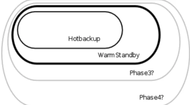
The feature itself is divided into four distinct phases, each of them being an improvement of the preceding one. These phases are also superficially described in the project briefing [1].
Figure 1.1: The various phases of the High-Availability feature
sl As depicted in Figure1.1, each phase intends to add something to the previous one in terms of improvement.
Introduction
1.1.1.1 Phase 1 - Hotbackup
Non-realtime, scheduled data replication was the main goal of the first phase. It involved getting an accurate snapshot of the data in the main server and the to automatically replicate it to a backup server, according to the schedule defined by the system administrator.
Any references to the Hotbackup feature that are made along this document are concerning the Phase 1 of edgeBOX High-Availability.
1.1.1.2 Phase 2 - Warmstandby
In the first phase, the operation was not made automatically, which means that in the case of failure, the admin would have to manually re-switch all the cables from the crashed edgeBOX. The second phase introduced the automatic failure detection and implemented the required management layer functionality to allow proper configuration of the feature.
Any references to the Warmstandby feature that are made along this document are concerning the Phase 2 of edgeBOX High-Availability, in which this document is completely based on.
This document will only be based on the second phase of the edgeBOX High-Availability feature.
1.1.1.3 Phase 3 - Warmstandby with real-time replication
The main flaw of the second phase is that data is not replicated in real-time. It works more like a Disaster Recovery solution. The fact that the two edgeBOXes are places near to each other, opens the doors to a real-time data replication, eliminating the need to stop some services during replication.
1.1.1.4 Phase 4 - Load balancing cluster
The last stage of this project aims at providing the edgeBOX with a complete Clustering suite, eliminating the waste of having a backup node that doesn’t have an active role in the system. This involves load-balancing network requests and also probably load-balancing incoming/outgoing calls through the use of custom designed hardware, such as Redfone foneBridge [2].
1.2
Project
As briefly explained in Section 1.1.1.2, this project’s main purpose is to imple-ment an automatic failover feature on edgeBOX, in order to allow the system to be
Introduction
configured with redundancy, and being tolerant to node failures, providing mecha-nisms to automatically recover from a crash without human intervention. The re-dundancy at the data level (replication) was assured in the first phase of edgeBOX High-Availability and was assumed, at the start of this project, to be implemented and fully working.
1.3
Objectives and Motivation
The motivation for this project comes from the growing demand for network availability and how people tend to increasingly rely on the local networks and the Internet simply to do their work.
In fact, in many organizations, when there is a network outage, many workers will simply stop because all their work processes depend on the instant access random information. This is especially true in the IT organizations.
Many businesses wouldn’t even exist it it wasn’t for the information technology. That’s the case of many well-known on-line stores and service providers, such as Amazon.com, eBay.com and others. As the data traffic figures rise, many organi-zations seek for ways of improving the aparent availability to their users, avoiding downtime (time during which the system is not available), which can help not loosing many clients, and thus, many potential earnings in money.
Following the already defined strategies for application development and imple-mentation in the edgeBOX system, this project intends to improve the product’s value by implementing High Availability functionality, which will allow the edge-BOX system to automatically recover from failures of various natures - hardware, cabling, software bugs, etc.
1.4
Document structure
This document is intended to deliver the most possibly accurate information about the whole implementation.
Besides this introduction, the document has four more chapters and, in the end some annexes
The second chapter provides some background information that is needed to un-derstand the context in which this project is inserted. This project is tightly related with some Clustering architectures and has many dependencies on the first phase (section 1.1.1.1). The High Availability software and the edgeBOX architecture (software and hardware) are also unveiled along the second chapter.
The third chapter features a more profound feature analysis, with the Require-ments Definition, use Cases and validation constraints. In a more technical context,
Introduction
this chapter presents some integration issues with the operating system and the Management Layer.
The fourth chapter describes the implementation with the highest possible level of detail. This includes not only design decisions and implementations, but also how the development was structured and how the collaboration with the entire team was accomplished. Detailed information on the modifications made to the software Heartbeat are also presented. The use cases present in the third chapter are extended with the corresponding Sequence Diagrams to show the interactions between the implemented modules. The final results and the way the feature is presented to the final user is also shown with a closeup on the Graphic’s User Interface and the Command Line Interface
Chapter 2
Background Information
This chapter describes the concepts that are behind this project, which help understanding the decisions that have been made and to better understand the technologies that have been implemented.
The edgeBOX is presented with a detailed description about the hardware, the operating system and some of the most important features as well.
The study on the concept of High Availability and Clustering helped providing a better idea of the current state of the art and what is possible of doing, as well as the possible architectures. This study has gone a little bit above the scope of this project because of the future development plans that had to be addressed in order to validate the viability and necessary effort.
The software Heartbeat from the Linux High Availability project is also shown here with incisive detail over the features that are relevant to this project.
2.1
The edgeBOX
The edgeBOX is Critical-Links’s flagship product, representing most, if not all, of the corporation’s activity.
It is a complete server suite designed to be the main gateway of an office or even a larger corporation. It is suitable for up to 300 simultaneous users, depending on the hardware the operating system is running on.
2.1.1 Features
All the services edgeBOX provides are based on Linux Open Source software, specifically modified according to the needs.
edgeBOX has with the following features:
• Access Router: being the corporation’s gateway, it provides its users with external access to the Internet with an access router. The administrator can use
Background Information
the Java-based graphical user’s interface to set routing parameters according to the company’s needs. It also allows the admin to set up Virtual LANs (VLANs) to better organize collision domains and logic topologies.
• Wireless Access point: edgeBOX can be equipped with a PCMCIA wireless card or it can be connected to an external Access Point to provide a wireless hotspot.
• File storage and print server: the Samba software and Cups print server provide edgeBOX users with file storage and printing facilities.
• Firewall security: edgeBOX features a built-in firewall that filters traffic and protects the network from external attacks.
• Internet telephony: alongside being certified for some ISDN/analogue cards, edgeBOX also provides IP telephony features using the software Asterisk. This way, the edgeBOX can be connected to the phone company network with digital (ISDN). The users can then use SIP or regular analogue phones to make calls. The administrator can configure default routes for specific phone numbers allowing the company to save money on phone calls.
• Network Access Control: the Network Access Control feature allows a more refined control on who gets access to the services. The edgeBOX client uses a web-based login panel to identify itself with the system.
• Web server and collaborative tools: edgeBOX has built-in HTTP and FTP web server and uses Squid to accelerate content delivery. As an add-on, the edgeBOX can be equipped with a Content Management System (edgeCMS), a Learning Management System (edgeLMS) and a Groupware tool (edgeEx-change).
• Mail server: The mail server allows the users to be provided with a mailbox where they can fetch their mail to their computers and also send main to the outside.
2.1.2 Hardware
The edgeBOX can be sold as bundle completely installed and ready to deploy or it can be sold in a CD with a proper license. There are three main appliance models, but the operating system can be installed in any hardware available, as long as it’s certified.
The available models are 3 - from the entry-level to the top, the Office, the Business and the Enterprise, each one supporting up to 40, 100 and 300 simultaneous users.
Background Information
Figure 2.1: Office, Business and Enterprise models
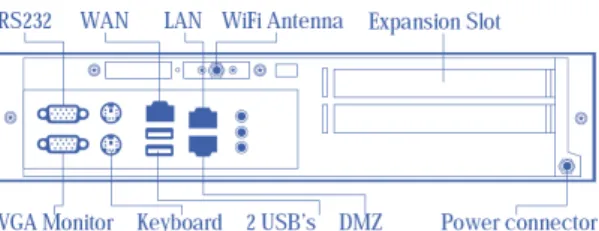
2.1.2.1 The cases
With the exception of the Office model, all the others use rack-mountable cases. On the back, the available connection ports are similar, among the various models, but again, with the exception of the Office model that lacks an important port (the AUX Ethernet interface) for the Warmstandby feature. In all the models that have the AUX interface, it is bridged with the LAN interface by default, and as such, it doesn’t make a difference to use one or the other.
Figure 2.2: Office model - back casing
Figure 2.3: Business model - back casing
Figure 2.4: Enterprise model - back casing
Figures 2.2, 2.3 and 2.4 show the back connection ports available in the three models.
Background Information
The importance of the AUX interface in the implementation of the Warmstandby feature will be explained some pages ahead in Section 3.1.
2.1.3 Telephony interfaces
One of edgeBOX’s main characteristics is the telephony subsystem. It can be connected to the digital or analog network through a regular service provider. The VoIP subsystem and the analog interfaces allow the edgeBOX to interconnect a virtually unlimited number of SIP (Session Initiation Protocol) telephone stations with the analog lines. This allows the edgeBOX to act as an intelligent telephone central, enabling the administrator to select the better routes for each kind of call.
The telephony interfaces are generally PCI cards with configurable number of slots. The user can use any configuration, as long as the required number of inter-faces is supported by the hardware.
2.1.3.1 Analog phone lines
The edgeBOX’s support for analog telephony telephony is a feature that strongly differentiates edgeBOX from it’s closest competitors, and as such, is very important. With this feature, the edgeBOX can integrate analog, digital (ISDN) and VoIP communication.
The analog telephony interfaces can be set up with configurable number of each of the following connections:
• FXO (Foreign Exchange Office) - a port that connects directly to a regular analog telephone, which in technical terms, is a FXO device. It provides the required power for normal operation of the FXO devices.
• FXS (Foreign Exchange Station) - a port that connects to the phone service provider.
2.1.3.2 Digital subscriber’s line
The edgeBOX supports digital ISDN telephony, either PRI1 and BRI2.
Both these standards are ISDN. The only difference is that BRI aims at the home and small-business use, since it only carries two B-channels and one D-channel, while PRI carries 23 (T1 - USA/Japan) or 30 (Europe/Rest of the world) B-channels and one D-channel.
The B-channel carries voice and data while the D-channel carries signaling and control information ([3][4]).
1
Primary Rate Interface
Background Information
2.1.4 Management Layer
The edgeBOX features a unified Management Layer that makes the configuration of the various components very simple, using a technology-centric point-of-view, that allows the user to see the configurations at a higher level, keeping an abstraction layer that hides the component specific configurations, and exposing to the user only what matters to alter the configurations according to the needs.
The Management Layer interacts with the user either through the GUI (Graph-ical User Interface) or through the CLI (Command Line Interface).
2.1.5 The Hotbackup feature
As briefly explained in Section 1.1.1.1 (page 2), Hotbackup is the first phase of the whole High-Availability feature of edgeBOX.
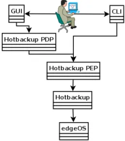
As such, Warmstandby indends to add new tecnologies. Since there are many ”sticky patches” careful consideration has been taken when choosing/modifying fea-ture architecfea-ture. In fact, the relationships between the modules have been slightly altered.
Figure 2.5: Relationships between Hotbackup compoments
As represented in Figure 2.5, the Administrator uses either the GUI or the CLI (Section 2.1.4) to access and modify the edgeBOX configurations.
Since the GUI is accessible though a Web Browser, it first has to pass though an interface, which is called the PDP (Policy Decision Point). The PDP is very close to a Java servlet, and each functionality has its own. The session variables for the communication with the configuration applet are maintained at this level. The PDPs make the link between the GUI and the PEP server.
Background Information
The PEP server allows the access to the edgeBOX management modules (the PEPs - Policy Enforcement Point). The GUI (through the PDP) and the CLI use the PEP modules to view and apply the configurations to the system.
Each PEP is a Perl module that may interact with other modules or directly with the system. The modules are kept in a tree structure that eases the comprehension by dividing big modules into smaller sub-modules.
2.2
Clustering
In computer terminology, a Cluster is a group of computers that work together, providing the outside users the illusion there is only one computer on the other end. Clustering’s main goals are introducing hardware fault tolerance on the system (High Availability), dividing network load between the nodes (Load Balancing) or even delivering higher levels of computing performance (Grid Computing).
The node is the single computer that is configured to work with the other nodes in order to achieve the goals described above.
2.2.1 High-Availability
High-Availability systems have the main goal of providing the lowest possible downtime sensation to the end user. Generally, a High-Availability system can automatically recover from:
• Hardware faults;
– Hard drive failures
– Power Source Unit failures – Other hardware failure • Network faults;
• Software faults (bugs, etc)
In High-Availability, highly available data doesn’t mean strictly correct data. It may be acceptable to have a system that, in the case of failure in the main node, doesn’t provide a strictly equal copy of it’s data. The important thing is that the system provides a service to it’s user at all times, or at least as much as possible.
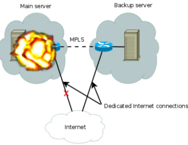
As such this technique doesn’t require advanced or distributed data replication. This kind of systems are commonly used for Disaster Recovery, which consists of having a main server and a backup server at a remote location. This would allow a system to recover from a situation that inflicted serious damage in the main location
Background Information
(a hurricane or an earthquake, for example). In this kind of scenario, having a regular Highly Available system in the main location would not help reducing downtime because all the nodes would be affected simultaneously.
Figure 2.6: Example of a Disaster Recovery system
Since geographically separated locations generally do not have a reliable connec-tion between them - when compared to Ethernet - (MPLS - MultiProtocol Label Switching -, for example, as depicted in Figure), the data replication is made using different mechanisms. Generally, the administrators use scheduled replication (once or more per day). The data is not real-time replicated, but at least it’s safe that there will be an acceptable snapshot of the data once the main location is down.
2.2.2 Load Balancing
The key difference from simple High-Availability to Load Balancing is that the first one has the inconvenient of the standby nodes being useless until the main one actually crashes. During the rest of the time they are just wasting energy. In Load Balancing, the nodes are simultaneously active, overcoming this problem of the High-Availability while keeping all its benefits. However, a Load Balancing Cluster involves a more complex network configuration.
The most common way to implement Load Balancing is to use a special network hub. Besides being able to route IP addresses, the hub has to work at the 4th layer (Transport) level, allowing it to redirect packets that are destined to one IP address to one of two or more computers. Generally, this kind of hardware uses a Round-Robin3 algorithm to maintain the load as equal as possible between the
nodes.
3
In best-effort packet switching, the Round-Robin algorithm is an alternative to first-come-first-served queuing and produces better results when the requests have similar sizes.
Background Information
Figure 2.7: Load Balancing system
2.2.3 Measuring performance
If a single computer has an independent probability p of becoming unreachable, a set of n similar nodes will have a probability of becoming unreachable given by the formula represented below:
pn
or, we can also calculate total availability by calculating the inverse[5, page 554]: Availability= 1 − pn
This means that, for example, if a single node has an independent probability (of becoming unreachable of 5%, it’s availability will be 95% . For a Cluster with two similar nodes, the overall probability of total failure will be
Cluster Availability= 1 − 0, 052
The conclusion is that adding another node to the cluster will significantly im-prove the overall availability.
• 1 node: Availability= 95%
• 2 nodes: Availability= 1 − 0, 052 = 99.75%
• 3 nodes: Availability= 1 − 0, 053 = 99.9875%
Background Information
These values as just representative or may be used for estimation purposes only. Precisely measuring a particular system’s availability can only be done empirically.
2.2.4 Split Brain
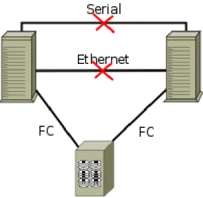
A concept that has always to be kept in mind when configuring High-Availability clusters is the Split Brain scenario. This happens when all the nodes loose all communication between them, which means all of them will ”think” they are alone and act as such.
Figure 2.8: Split Brain scenario in shared storage system
This scenario is generally avoided with the use of redundant communication channels (using the serial port, for instance), which reduces the probability of to-tal communication failure. However, it is always possible, and it can bring lots of complications in particular cases. Figure 2.8 shows a situation where the cluster uses a shared storage through Fibre Channel 4. The system is out of communica-tion (Ethernet and serial), which might lead to data loss and inconsistency, due to unsynchronized access to the same areas of the storage system.
The solution to this problem is commonly the STONITH5 device. It’s a simple device that may come in various flavours (serial/Ethernet/other) and many times, it’s the last resource for a taking over node to make sure the other one is completely turned off, unable to make any kind of damage.
The STONITH device is not more than a remote power switch. However, the power switch was primarily created with the purpose of being controlled by an
4Fibre Channel is a gigabit network technology primarily used for storage networking. The Fibre
Channel Protocol (FCP), similar to TCP, transports SCSI commands over Fibre Channel networks[6]
5Shoot The Other Node In The Head
Background Information
Figure 2.9: iBoot power switch by Dataprobe
administator. The STONITH device is generaly activated by software that manages the High Availability cluster (Heartbeat). Figure 2.9 shows an example of a simple remote power switch made by Dataprobe6.
2.3
Linux High-Availability project - Heartbeat
The High Availability Linux project is a widely software package, providing a high availability (clustering) solution for Linux which promotes reliability, availabil-ity, and serviceability (RAS) through a community development effort[7].
Many organizations use this software to improve their availability and, in some cases, maximize their profits. These organisations act in various fields, such as Education, Engineering, Media and Transportation [8].
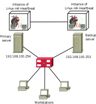
When configured in the system, Heartbeat is a running daemon that maintains communication with all the nodes that are known. In Figure 2.10, the depicted scenario features a High Availability cluster running Heartbeat on the background. The system is running in Automatic Failover mode, which means there is only one node active at a time. The nodes are actively sending keep-alive messages to each other, so that both instances of Heartbeat maintain an up-to-date status of the Cluster. In the outside of the Cluster, the users only now the Primary Node’s IP address (either because it is statically configured in all the computers or because it’s where the DNS points to), so the Backup Node is completely invisible outside the Cluster.
In the case the Primary Node crashes or stops responding, it will stop sending keep-alive messages to the instance of Heartbeat running in the Backup Node. Once the time lapse counting from the last message that was received from the Primary has exceeded the configured timeout, the Backup node will activate all the actions
Background Information
Figure 2.10: System running heartbeat
Figure 2.11: Primary node failure
Background Information
required to make it ”wear the Primary node’s skin”. In the most simple cases, this can be as simple as changing the IP address to the one that was being use by the Primary when it crashed.
2.3.1 Managing Resources
Heartbeat uses the concept of Resource to describe what it can be seen as a ser-vice do the end user. For example, when a cluster is exclusively dedicated to serving web pages, the main Resource might be Apache HTTP Web Server, which can be controlled by an init script defined accordingly to the LSB core’s7 specifications.
This means the Resources can be controlled with simple start/stop/status oper-ations. When the Cluster is brought up (the nodes are powered on), the resources are not activated during startup on regular init. This operation is controlled by Heartbeat instead. Once it is ran and manages do get in sync with the other nodes in the Cluster, it will decide, according to the configured policy, which one should be the node running which resources (Section 2.3.3.3). After this decision is made, Heartbeat will start all the resources that should be started.
This is accomplished with the use of the equivalent to the init scripts that start the services. The process will be explained with more detail in Section 2.3.2.
2.3.2 OCF scripts
Heartbeat can virtually control any kind of resource, as long as it is scriptable or, in other words, as long as it can be controled from a regular console using shell-like commands.
For such purpose, it uses the OCF (Open Clustering Framework), which is not more than an extension of what’s defined by the Linux Standard Base (LSB) Core Specification[9] regarding the init scripts standards.
The LSB specification states that the init script of a given application should support the following operations:
• start - start the program/aplication • stop - stop the program/aplication
• restart - stop and start the program/application
• force-reload - force the program/application to reload the configurations • status - check the current running status of the program/application
7
The LSB (or Linux Standard Base Core) is a organization that belongs to the structure of the Linux Foundation and has the objective of standardize the internal structure of Linux-based operating systems.
Background Information
OCF scripts are also written according to their own specification[10].
In Heartbeat, the OCF scripts are used as the Resource Agents, or in other words, the scripts that are used to start, stop or view the current status of any given application.
Being an open standard, the OCF specification allows the programmer to write code to virtually control any kind of Resource Agent. Besides being able to start and stop regular services, it can also configure or deconfigure network interface cards - this is especially helpful to make the secondary node assume the primary’s IP address when it fails. In fact, this Resource Script, which is called ”IPaddr” in Heartbeat’s distribution, is the one to be used by default when no particular is specified (Section 2.3.3.3).
2.3.3 Configuration and status files
Heartbeat relies on configuration files that can be edited with a simple text-based editor. These files are read during the startup process.
All of them as located in the /etc/ha.d directory (default).
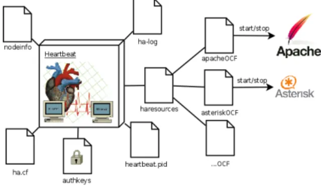
Figure 2.12: Heartbeat configuration files
Figure 2.12 represents the configuration files needed by Heartbeat. Each one of them is described with detail on the next sections.
Heartbeat 2.x uses a different set of configuration files. However, since the second version of this software is beyond the scope of this project, it will not be detailed here.
2.3.3.1 ha.cf
ha.cf stores the most important configurations Heartbeat needs to run. Since there are many possible configuration directives, this document will only detail the ones that were used for the implementation.
An example of a configuration for ha.cf would be:
Background Information crm off debugfile /var/log/ha-debug logfile /var/log/ha-log logfacility local0 keepalive 1 deadtime 5 warntime 4 initdead 10 auto_failback off node node1 node node2 baud 19200 serial /dev/ttyS0 udpport 694 ucast eth0 192.168.1.1 ucast eth0 192.168.1.2
The directives that were used are described as follows [11]:
• crm: <on/off> specifies whether Heartbeat should use a version 2 configura-tion or a regular version 1. As it was stated in Secconfigura-tion 2.3.3;
• logfile: <file> specifies the location of the main log file;
• logfacility: <file> specifies the logging facility that should be used - refer to syslog.conf8 documentation for further info;
• keepalive: <interval> time lapse between two heartbeats;
• deadtime: <interval> maximum time during which there was no communi-cation until the node is considered dead;
• warntime: <interval> time before Heartbeat issues a late Heartbeat warning; • initdead: <interval> time, during the start-up process, before Heartbeat
considers a node as being dead;
Background Information
• udpport: <port> UDP port to be used for the Ethernet Heartbeat monitor-ing;
• baud: <baud rate> baud rate to be used in the serial-based Heartbeat; • serial: <serial device> serial device to be used (/dev/ttyS0);
• auto failback: <on/off> defines how heartbeat should act. If set to ”on”, the non-preferred node will always fail back to the preferred node. Otherwise, they will only switch when the active node crashes;
• node: <node name> specifies the name of a node. There has to be as much ”node” directives as nodes in the Cluster;
• ucast: <NIC> <IP> specifies the network interface card and the IP address to which Heartbeat should send packets to (UDP unicast).
2.3.3.2 nodeinfo
The name for the node can be specified in this file. To set the name as ”node1”, it should be written as the only content of this file, as represented below:
node1
In case this file doesn’t exist, Heartbeat will get the hostname of the computer and use it instead.
2.3.3.3 haresources
This file is used to specify the resources that should pass from one node to the other in case of failure.
Each line in this file defines a resource group, or in other words, the group of resources that should be transferred from one node to another in case of failure. Generally, it’s written according to the following format:
$<$node name$>$ $<$resource type1$>$::$<$parameter 1$>$/.../$<$parameter n$>$ ... where there is only one node name - the preferred node to handle the resource(s)
-and one or more resource types with its parameters (optional, depending on the resource type itself - IPaddr resource, for example, requires the IP address to be specified).
node1 IPaddr::192.168.1.1/eth0/255.255.255.0
Background Information
In the example given above, the resource that is being transferred from one node to the other in case of failure is the IP address of the eth0 interface, which should be 192.168.1.1/netmask255.255.255.0 for the active node. The preferred node to serve this resource is node1.
It is also important to refer that when the resource type is not specified, it is assumed to be IPaddr. The configuration shown below does exactly the same thing as the one above.
node1 192.168.1.1/eth0/255.255.255.0
2.3.3.4 authkeys
The authkeys file should contain information that the node members should use to identify other Cluster members. There are 3 ways of signing the messages:
• crc: uses a CRC hash to verify the message - doesn’t require a key, so it’s insecure;
• md5: uses the md5 hash and the key to verify; • sha1: uses the sha1 hash and the key to verify; auth 1
1 sha1 edgeBOX-HA
The method is specified in the line <number> <method> [key]. The file can contain several methods, each one being identified by the corresponding number. The directive auth <number> specifies which key should be used.
Chapter 3
Requirements specification
The general objectives of this project have been thought out since the beginning, but there is the need to have a comprehensive description of the intended purpose and environment for software under development. This chapter describes what the software does and how it is expected to perform, as well as how it is going to interact with it’s users and the hardware.
3.1
Network topology
To better understand the environment in which the software will be deployed, it becomes necessary to describe the network architecture in which the system will work.
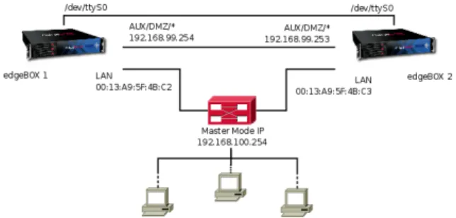
Figure 3.1: edgeBOX network topology with Heartbeat
The network topology represented in Figure 3.1 was designed to feature the following elements:
• Redundant serial link - Point-to-point serial connection to avoid Split Brain scenarios (Section2.2.4);
Requirements specification
• Ethernet link - Ethernet connection through the LAN interface for connection to the local network, data replication between the edgeBOXes;
• Dedicated Ethernet link - being optional, gives the System Administrator the option of using either the DMZ or the AUX port (when available) to make the data replication and the Heartbeat monitoring exclusively.
In regular system operation, the Master edgeBOX has always the same IP which is known by the users that are connected in the local network (through DHCP). The Slave edgeBOX uses an IP address that belongs to the same subnet as the Master’s. In case of failure, when the edgeBOXes switch status (Master to Slave and vice-versa), they must also change the IP address that’s been assigned to them during configuration (which is assured by the Slave being mirrored with Master’s data).
3.2
High-level requirements
There are some requirements that had to be satisfied in order to fully integrate the Warmstandby feature with edgeBOX. These are described in this section.
3.2.1 Failure detection
Failure detection is the most important requirement of this project. The system has to be capable of monitoring the active node and take-over when it fails. It has been decided from the beginning that the software Heartbeat would be the chosen tool for this purpose, because it fits most of the needs that have been described over Section 2.3.
This involved a profound study that contributed for a good idea of the needed modifications for this phase, but also for getting an idea of the needed effort that will have to be made to continue using Heartbeat as the base for the next phases, and also if it would be viable.
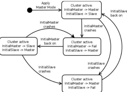
Figure3.2 features a State Diagram that describes how the various states which the systems goes through and the events that lead to each one. InitalMaster and InitialSlave refer to the the edgeBOXes that were initially configured as Master and as Slave, respectively. Since there is no preferred node - a node that is always active (Master) when present -, the roles are may completely invert - the node that was initially configured as Master becoming Slave.
Requirements specification
Figure 3.2: Cluster Behaviour State Diagram
3.2.2 Integration with the Operating System
The process of integrating the feature with the operating system dictates that all the required packages have to be studied and their dependencies identified, so that all of them can be included in edgeBOX’s package system. The software has to be successfully compiled in the building environment and successfully ran in the testing computers prior to being integrated in the operating system release.
After all the packages are built, it has to be possible to install the whole fea-ture without user intervention other than a simple install command or equivalent (provided by the packaging system[12]).
3.2.3 Integration with the Management Layer
The feature has to be fully integrated with the Management Layer, which means that all the configurations susceptible of being changed by the System Administrator need to be identified and implemented in user-friendly interfaces (The GUI and the CLI). It is not acceptable in any way that the System Administrator needs to use any tool other than the ones that were just specified to use the Warmstandby feature.
The user doesn’t need to know how to configure Heartbeat. Just to know (as it will be specified in the User’s Guide) that if the Warmstandby feature is activated, the system will behave in the expected manner - refer to Section3.2.1.
Requirements specification
3.2.4 Phone line switching
edgeBOX’s telephony features are amongst the most important ones, which forces the implementation of the Warmstandby feature to support phone line switching.
Phone line switching is an important part of this project, since the telephony features of the edgeBOX are one of its most important characteristics. It does complicate things a little bit, because Heartbeat only works around the switching between the active and the passive node.
Figure 3.3: Need for phone line switching
Figure 3.3 represents a scenario with two edgeBOX and an automatic failover scenario. The connection to the ISP (Internet Service Provider) - WAN - is Ethernet-based. The same works for the LAN, AUX and DMZ, which means all of these links don’t need to be physically switched - the Layer 2 switch maintains the scnenario valid when the edgeBOXes switch roles. However, the same doesn’t happen with the other lines - PRI, BRI and Analog.
In a Hotbackup scenario, these lines would have to be manually removed from the Master and connected to the Slave. However, this is not acceptable for an automatic failover scenario, reason why the system must be prepared to use hardware devices built for this purpose.
Requirements specification
3.2.5 STONITH devices
The system must be prepared to deal with Split Brain scenarios, giving the System Administrator the choice of using it or not, eliminating the risk of having two nodes owning the same IP address - which could lead to erroneous IP attribution (two concurrent DHCP servers, for example).
3.3
Use cases
Being the objective of the Warmstandby feature to make the configuration as simple as possible, the use cases have been reduced to the minimum. The adminis-trator has a small set of possible actions to control and configure the cluster.
Figure 3.4: Use Cases diagram
Figure3.4 shows the Use Cases packages that were implemented in this project. The main interactions with the system are described in Section 4.4.
3.3.1 Actors
The actors that can interact with this system are only two:
• System Administrator: the user that configures all the settings there are to be configured, by using the GUIs (Section4.7) or using the CLI ;
• Failure: a fictitious user to use in place of any possible form of system failure that originates the failure of the Master.
Common edgeBOX users are not supposed to even notice that the Warmstandby feature exists.
Requirements specification
3.3.2 Master Cluster Management package
The Master Cluster Management package includes the main operations of the ones directly related to the Warmstandby module. When configuring the cluster, the administrator will only have to use the Master GUI to activate the automatic monitoring function.
3.3.2.1 Activate Cluster
When the Administrator activates the Cluster, the edgeBOX being configured as Master will find the Slave and will follow a step-by-step process to validate all the configurations and dry-run the system before considering the configuration valid.
The expected behaviour is a confirmation box informing the System Adminis-trator that the process was completed with no problems of any sort.
3.3.2.2 Disable Cluster
Disabling the Cluster is a delicate operation because it means first disabling all the High-Availability subsystem in the Slave edgeBOX (it might unexpectedly take over otherwise), and then removing all the configurations.
After a successful disable, the Master edgeBOX will behave as one with no Hot-backup or Warmstandby configurations whatsoever. The Slave itself should continue as such, except the Warmstandby feature must be disabled.
3.3.2.3 Remove Master
In some cases, the Administrator may want to remove the Master edgeBOX from the Cluster - for maintenance reasons, such as replacing a noisy PSU. Of course it is possible to just unplug the switch and let the Slave detect Master absence and take over, but it is tidier to have an operation that allows the Slave to come up before the Master shuts down, avoiding a long downtime period.
3.3.2.4 Configure AUX port
In order to use the AUX port as a dedicated interface, it becomes necessary to configure it first with valid IP settings so it can reach the Slave edgeBOX, if it is configured to listen to the AUX port as well.
This was implemented as a separate step from the overall Cluster activation procedure since it should be done prior to it.
Requirements specification
3.3.3 Slave Cluster Management package
The Slave operations are simple. Since it is supposed to act as completely passive after a successful configuration - such as in regular Hotbackup mode -, the only extra configuration needed is the port that should be used.
3.3.3.1 Choose Ethernet Port
The choice of the Ethernet port lets the Administrator explicitly state which one should be used. The system should choose a default one if none is specified. For the sake of consistency, the system should use the LAN interface. This will keep the feature very similar to Hotbackup. In fact, configuring the Slave to be used in Warmstandby mode is exactly the same as configuring it to be used in regular Hotbackup mode. The only difference is that with the introduction of the Warmstandby feature it is now possible to chose which port to choose for data replication.
3.3.3.2 Activate Slave mode
After the System Administrator chooses to apply the Slave Mode, all the settings are verified and the system starts applying them, rebooting in the end into Slave Mode. A panel showing all the configurations should appear in the command line interface when done. The LCD should also show this information.
3.3.4 Advanced settings
The advanced settings section should support any other configuration that is not strictly needed to run the edgeBOX in Warmstandby mode. This includes configuring external hardware (layer 1 switches or STONITH devices).
This section should also be open to future improvements of the Warmstandby feature.
3.3.4.1 Choose to use STONITH devices
Sometimes the Administrator may want to use a STONITH device. From the user’s point of view, the configuration should be as simple as crossing a check box and see a confirmation dialog stating ”Device found and correctly configured”.
3.3.4.2 Choose to use Layer 1 Switch
Choosing to use a Layer 1 Switch should be similar to the STONITH device selection.
Requirements specification
3.3.5 Automatic failover
The Slave should be equipped with a failure detection mechanism (provided by Heartbeat) that can trigger the appropriate actions in the case of failure.
3.3.5.1 Take-over
Take over is the set of actions that the Slave edgeBOX has to make in order to become the Master. This should be done automatically with not user intervention whatsoever.
Chapter 4
Implementation
This chapter is dedicated to the description of all the work that was done during the development stage.
It starts by giving an overview on the parts of the architecture that had to be modified. Since the architecture is composed of several layers, not only the isolated changes will be detailed, but also most of the interactions between each layer.
It is also important to show the aspect of the GUI
In the final section, there is a general overview of all the packages that were implemented on the system as well as the dependencies between them.
4.1
Integration of Warmstandby with Hotbackup
As stated in Section2.1.5(page9), the Warmstandby feature has ”sticky patches” with the Hotbackup feature.
Figure 4.1: edgeBOX WarmStandby architecture
Implementation
Figure 4.1 shows the previously existing Hotbackup architecture (left) and the Warmstandby architecture with the modifications it implemented. The operation flows are identified with the corresponding arrows.
The Warmstandby module had to be created from scratch. That didn’t happen with Hotbackup module, the GUI and the CLI, which just needed modifications.
The requests that are processed by the Hotbackup PEP had be redirected to the Warmstandby module. Most of the regular Hotbackup functions are simply by-passed to the Hotbackup module, but others need some adicional processing. It’s the case, for example, of the Cluster Disable operation (Section 4.4.2).
4.2
Management modules
The management modules have been structured in order to improve their com-prehensiveness. There is a main module (Warmstandby) that is used by the layers above. The modules that sid underneath it were separeted in several files, making them smaller and easier to understand.
Figure 4.2: Management Modules
Figure4.2 represents the modules that were implemented for the Warmstandby feature. Each of them is described with more detail along the following subsections.
4.2.1 WarmStandby
WarmStandby is the main module for the Warmstandby feature. All the action flows pass through it, as represented in the Sequence Diagrams shown along Section
Implementation
It wraps up all the routines that have to be called by the Hotbackup PEP but most of the logic required for the Warmstandby feature is within the logic to the modules that sit right underneath it.
4.2.2 Definitions
The common variable definitions are placed in this module. It is useful as a common point to define names, file locations,
4.2.3 Cluster
All of the operations directly related with the High-Availability subsystem are triggered from this module.
It wraps up routines to:
• Remotely execute commands in the Slave edgeBOX • Control Heartbeat locally (start/stop/status/restart) • Control Heartbeat remotely
• Heartbeat dry-run check (on both Master ans Slave) • Heartbeat run check (on both Master ans Slave) • Get configurations from the Slave
• Install the cluster configurations 4.2.4 Logs
The logging module intends to set-up a common logging facility for all the mod-ules in this package
4.2.5 Serial
This package provides the required routines to manage the serial console inte-gration with the Warmstandby feature, such as verifying if it is being used by any other feature, and if so, configure it to be used exclusively with Warmstandby. 4.2.6 Configs
This module comprises a set of routines to manage the Warmstandby feature’s specific configurations. It helps setting and storing configurations and provides a friendly interface to fetch the configurations in use.
Implementation
4.2.7 Layer1Switch
The module that integrates the Layer 1 Switches with the system keeps a common set of routines that wrap specific calls to all the supported devices, providing an easy way to:
• Check for existing switches on the subnet; • Store a list with all the information about them; • Configure the switch(es) one by one or all at once; • Activate watchdogs for one or more devices; 4.2.8 HeartbeatDiagnostics
The Heartbeat Diagnostics module comprises all the routines to get diagnostics from Heartbeat, which provides the utilities to signal Heartbeat process and fetch the information directly from the logs, returning only the status of each link. 4.2.9 Mode
The mode module is used switch between Master and Slave mode, wrapping the required actions.
4.2.10 Status
This is a simple module that provides a quick way of finding in which Mode the cluster is running.
4.2.11 Interface
The interface module provides the required routines to deal with the configura-tion of the various interfaces, such as configuring AUX, removing or adding it to the bridge (Section 2.1.2.1).
4.3
Support for Layer 1 switch
The Layer 1 Switch is the device responsible for the phone line switching. There are many types of devices available with many possible configurations. However, it was established that all the supported devices should have Ethernet-based remote administration - many use serial-based administration.
Figure 4.3 shows the usage of a typical layer 1 switch. This kind of device generally works in two modes - normal and failover. It cannot operate in both
Implementation
Figure 4.3: Usage of a layer 1 switch in failover scenario
modes at once. The difference between them is the ports that are by-passed. The device represented in the figure has five groups of 4 ports each. The first group is directly connected to the phone service provider or analog phones - everything that could be plugged directly to the edgeBOX in a regular deployment scenario.
On normal operation, the switch physically connects the ports in the first group to the ports in the third group, which, for instance, are connected to the active edgeBOX. However, in failover mode, the switch can internally unplug the ports in the third group and bypass to the fourth group, which is connected to the redundant edgeBOX.
The process that triggers the line switch is done in several ways:
• When first configured, the devices are activated and configured to their normal operation mode;
• The devices have a hardware watchdog - a system that needs to receive constant updating and triggers some action when the time lapse since the last update exceeds the maximum timeout - which sets the device in failover mode once the ”feeder” stopped responding (in this case, the ”feeder” would be edgeBOX on the left);
Implementation
• When taking over, a node will make sure the switch is set to the proper mode by applying the correspondent configuration.
Since the only device that was used until now needs to be assigned an IP ad-dress (with DHCP) before being configurable, it was established that it should be connected to the LAN segment.
The security is also a concern - having a device that can be remotely configured and, if maliciously used, can cause system malfunction is not acceptable.
This is why the device should support authentication and secure communication. As such, when first configuring, the system creates and stores a password on the switch. This password should only be known by:
• The layer 1 switch; • The Master edgeBOX; • The Slave edgeBOX.
4.4
Sequence Diagrams
Each action from the user triggers a whole process that involves interactions between the modules that implement the solution [13, page 68]. As such, the Use Cases that were defined in Section3.3 (page25) will be detailed in this section with the corresponding sequence diagrams.
4.4.1 Activate Cluster
The Activate Cluster Use Case is described in Section 3.3.2.1. However, the sequence diagram represented in Figure 4.4 will give a better idea of the actions that take place when the user triggers the operation.
With the purpose of introducing some reliability on the action, all of the opera-tions are verified and propagated back to the user, returning no problems or error, if that’s the case.
The most important and critical step of this operation is activating Heartbeat. In order to securely test the operation, the script does a dry-run, configuring Heartbeat with all the configurations that will be used with the exception of the resources that are to be managed. This was decided because using the default OCF resource Script could inadvertently set the Slave in Master mode and vice-versa.
The dry-run consists on activating Heartbeat first on the Master (which will be our primary edgeBOX) and then on the slave (to assure the first one is the the initial master, as expected. After this step is completed, HeartbeatDiagnostics module is called so that the running information from heartbeat can be fetched.
Implementation
Figure 4.4: Activate Cluster sequence diagram
Implementation
4.4.2 Disable Cluster
The Cluster disable operation is very simple, but it must follow a strict order in the actions that are made.
Figure 4.5: Cluster Disable sequence diagram
Figure4.5 represents the interactions between modules that have to be made in order to complete this operation.
First the system tries to get the Slave’s IP and check for its availability (the Slave has to be present for this operation to be successful). If not present, a single node Warmstandby shutdown will be done - this can lead to Slave takeover, if for some reason it is present and working but not available through the network. Otherwise, if the Slave is correctly detected, the Warmstandby configurations will be removed, which implies:
• Stopping Watchdog daemons for STONITH devices and layer 1 switches; • Resetting Warmstandby configuration files;
• Bridging back the AUX and LAN interface (if applicable).
The Heartbeat shutdown procedure should be first done in the Slave and only after that, if successful, in the Master. If this is not done following this order, there is the risk the Slave may inadvertently take over.
Finally, all the Hotbackup configurations are removed in the Master edgeBOX. This last part is done by the Hotbackup module, exactly as it was previously im-plemented.
Implementation
4.4.3 Remove Master (Maintenance)
Since removing the Master edgeBOX is a maintenance and programmed action, it is useful to avoid the time the Slave takes to detect Master’s absence - the ad-ministrator could just unplug the Master edgeBOX and the Slave would take-over after the defined amount of time. However, the ideal scenario happens if the Master edgeBOX, after a programmed shutdown, only really turns off when the Slave has started the take-over procedure.
Figure 4.6: Remove Master sequence diagram
The procedure is completely described in Figure 4.6.
4.4.4 Configure AUX port
Configuring the AUX port has a static and a dynamic component. Because, unlike the Slave configuration (Section 4.4.6), this one has to be applied without system reboot, it has to be stored in the configuration files
Figure 4.7: Configure AUX sequence diagram
4.4.5 Choose Ethernet port
The Ethernet port choice follows the Slave activation flow, although this is not perceptible by the user, since the logic is embed in the GUI. If the user does not
Implementation
specify a communication port, it will be assumed that the LAN port is used. Either way, the port to be used will always be passed to the Management Layer by the GUI, with an indication stating whether the user selected the port itself or if it was the default choice.
4.4.6 Activate Slave mode
Activating the Slave mode is a very simple operation that doesn’t add much to the existing Slave mode in the HotBackup feature. In fact, it is basically the same as the former, except that it allows the choice of the Ethernet replication port.
Figure 4.8: Activate Slave sequence diagram
As represented in the diagram in Figure 4.8, the operation starts by setting the configuration files directly in the system - with no dynamic changes, since the configurations will be applied after a reboot.
After that, the already existing facility for setting up the HotBackup Slave mode is called to finalize the operation. The system is rebooted, but before it happens, the GUI receives the success status of the operation so the user knows what happened.
4.4.7 Choose to use Layer 1 Switch
Configuring the layer 1 switch is done in two steps. When the appropriate form in the GUI is loaded, it lists all the available devices found on the network.
Figure 4.9 is a Sequence Diagram showing the interactions. When the form is loading, the GUI requests Hotbackup PEP for the available devices. The request is propagated down to each of the supported devices (there was only one at the moment this document was closed). The discovery process can change from device to device, but generally, the control application broadcasts a UDP packet that was designed to be recognized by the switch device. The switch replies with its status information (IP, MAC address, operational status, etc). If there is more than one device - there can be in some special cases -, they will all be listed in the GUI.
Implementation
Figure 4.9: Layer 1 Switch Sequence Diagram
Showing the devices in the GUI is more a way of providing the user with visual proof that the device that was attached is being detected. In the next step - activa-tion -, there is no special informaactiva-tion being passed to the activaactiva-tion routine. What it does is getting a fresh list of devices and storing/applying all the configurations, which translates in:
• Creating a configuration file with all the detected devices; • Configuring all the detected devices for normal operation mode;
• Activating a watchdog daemon to ”feed” the watchdogs (there will be one watchdog daemon for each existing layer 1 switch).
4.4.8 Choose to use STONITH device
Configuring the STONITH devices is very similar to the configuration of layer 1 switches. In fact, the only STONITH device supported by the time this document was closed is also the layer 1 switch that was referenced earlier. Besides providing line switching, it also has two built-in remote power switches that can be used for this purpose.
Figure 4.10: STONITH devices Sequence Diagram