Analysis of cyclic and long-term effects in continuous precast railway bridge decks
371
0
0
Texto
(2)
(3) Abstract. Important investments have been made worldwide in the modernization and construction of railway lines. Plans for new constructions, in the near future, have also been laid out. Recently, precast concrete has been widely employed in the construction of railway bridges and viaducts. Various prefabricated solutions have been applied, namely: I-shaped or U-shaped precast girders and uni-cellular or bi-cellular precast box girders. As regards the structural scheme in the longitudinal direction, either simple span or continuous decks have been used. In this context, this work aims to contribute to the knowledge about the real performance of these structures, and also to give a contribution in terms of numerical methods for analysis of this type of constructions. Special attention is devoted to continuous bridge decks constructed with precast U-shaped girders, without continuity prestress. This option is justified by the advantages offered by this solution, in terms of economy and ease of construction, and also by the specificities of its structural behaviour, which require special attention in terms of analysis and design. These specificities are: (i) the absence of post-tensioning to resist hogging bending moments above the continuity supports, which requires a detailed analysis of the structural behaviour after cracking; (ii) the adoption of thin webs and slabs, subjected to important cyclic stresses, which implies that their fatigue behaviour must be properly assessed; (iii) the relevance of the construction sequence and of the concrete delayed deformations, in terms of long-term variation of concrete stresses and internal forces. In view of these issues, this thesis comprehends four main parts. In the first part, a numerical model for the analysis of cracked RC elements subjected to cyclic loading is developed and validated. The adopted analysis strategy involves the explicit consideration of the cyclic bond stress-slip relationship between the tensile reinforcement and the surrounding concrete, and also the relationship between the normal stress at the crack and the crack opening under cyclic loading. The validation, through the comparison with experimental results reported in the literature, reveals that this model provides an accurate description of the non-linear behaviour of the tested elements subjected to cyclic loading. The second part focuses on the fatigue behaviour of railway bridge decks. Alternative procedures for fatigue analyses are presented, special attention being paid to analyses based on the damage accumulation method. An original methodology for fatigue analysis of girder webs, taking into account the effects of in-plane shear and transverse bending, is developed and validated. The main specificity of this methodology lies in a simple algorithm for calculation of concrete and. iii.
(4) stirrup stresses. The comparison between numerical calculations and experimental results reported in the literature reveals that the developed analysis procedures provide results on the safe side, and are suitable to be applied in the design practice. The applicability of the same procedures to problems of shear between web and flanges is also discussed. The third part is dedicated to the numerical analysis of the long-term behaviour of continuous precast bridge decks, considering the influence of concrete delayed deformations and phased construction. The results of finite-element phased analyses are compared with the experimental results observed in a real viaduct. A Monte Carlo simulation is employed to evaluate the relevance of the uncertainty associated to the quantification of concrete delayed deformations and construction timings. In the last part, the previously developed and validated numerical methodologies are applied in the analysis of a real railway bridge deck built with precast U-shaped girders, without continuity prestress. The variability of the long-term structure behaviour, owing to concrete delayed deformations and phased construction, is quantified and discussed. Fatigue and ULS analyses of the girder webs and of the top slab, considering in-plane shear and transverse bending, are shown. Stiffness decreases after cracking and residual crack openings are quantified taking into account the influences of traffic (cyclic) loading and concrete shrinkage. Detailed analyses based on the methodologies developed in this thesis are compared with the simplified approaches suggested by the Eurocodes, and conclusions about the relevance of the developed models are drawn..
(5) Resumo. Atualmente estão em curso importantes investimentos na modernização e construção de linhas ferroviárias. Existem também vários projetos para a realização de novas obras num futuro próximo. A pré-fabricação em betão tem sido empregue em larga escala nesses empreendimentos, para a realização de pontes e viadutos. Diversas soluções têm sido utilizadas, nomeadamente vigas pré-fabricadas tipo I e tipo U, e também vigas pré-moldadas em caixão uniou bi-celular. No que diz respeito ao esquema estrutural, têm sido empregues quer soluções isostáticas, quer tabuleiros contínuos. Neste contexto, pretende-se com o presente trabalho contribuir para o conhecimento acerca do desempenho real destas estruturas, e sobre as metodologias para análise do seu comportamento estrutural. O trabalho foca, em particular, nos tabuleiros contínuos construídos com vigas tipo U, sem pré-esforço de continuidade. Esta opção é justificada pelas vantagens económicas e construtivas oferecidas por esta solução, e ainda pelas especificidades do seu comportamento estrutural, que requerem cuidados especiais em termos de conceção e análise. Destacam-se as seguintes especificidades: (i) a ausência de pré-esforço de continuidade para resistir a momentos fletores negativos, o que requer uma análise cuidada do comportamento em fase fendilhada; (ii) a adoção de lajes e almas esbeltas, sujeitas a importantes carregamentos cíclicos, tendo portanto relevo o fenómeno de fadiga; (iii) a importância do faseamento construtivo e do comportamento diferido do betão, em termos de distribuição de tensões e esforços a longo prazo. Tendo em conta estes aspetos, esta tese é dividida em quatro partes principais. Na primeira parte, é desenvolvido e validado um modelo numérico para análise do comportamento cíclico de elementos de betão armado fendilhados. A metodologia de análise adotada envolve a consideração explícita de modelos que descrevem o comportamento cíclico, quer da aderência aço-betão, quer da relação entre a tensão normal a uma fenda e a abertura dessa fenda. A validação, através de resultados experimentais disponível na bibliografia, revela que este modelo permite descrever de modo rigoroso o comportamento não linear dos elementos sujeitos a ensaios cíclicos. A segunda parte incide sobre a fadiga dos tabuleiros de pontes ferroviárias. São apresentados procedimentos alternativos para a realização de análises de fadiga, sendo dada especial atenção às análises baseadas no método da acumulação de dano. É apresentada e validada uma metodologia original para análises de fadiga das almas das vigas, considerando os efeitos do. v.
(6) esforço transverso no plano e da flexão transversal. A principal especificidade dessa metodologia reside no emprego de um algoritmo simples para cálculo de tensões instaladas nos estribos e no betão. A comparação entre resultados numéricos e experimentais (publicados por outros autores) mostra que a metodologia numérica desenvolvida fornece resultados do lado da segurança e é adequada para ser empregue na prática. É também discutida a aplicabilidade dessa metodologia a problemas de corte entre alma e banzos. A terceira parte é dedicada à análise numérica do comportamento a longo prazo de tabuleiros contínuos pré-fabricados, considerando a influência do faseamento construtivo e das deformações diferidas do betão. Os resultados de análises faseadas baseadas em modelos de elementos finitos são confrontados com valores observados num viaduto real. É utilizada uma simulação de Monte Carlo para avaliar a importância da variabilidade associada à quantificação das deformações diferidas do betão e dos tempos de construção. Na última parte, os modelos numéricos previamente desenvolvidos e validados são empregues na análise de um tabuleiro ferroviário real construído com vigas pré-fabricadas tipo U, sem préesforço de continuidade. A variabilidade do seu comportamento a longo prazo, considerando as deformações diferidas do betão e o faseamento construtivo, é quantificada e discutida. São levadas a cabo análises de fadiga das almas e da laje superior, considerando o corte no plano e a flexão transversal. É avaliada a redução de rigidez associada à fendilhação, assim como a abertura residual de fendas, tendo em consideração os efeitos do tráfego ferroviário e da retração do betão. As análises detalhadas baseadas nas metodologias desenvolvidas nesta tese são comparadas com as abordagens simplificadas dos Eurocódigos e são retiradas conclusões sobre a relevância dessas metodologias..
(7) Résumé. Actuellement, des investissements importants sont faits dans le monde entier pour la modernisation et la construction de lignes de chemin de fer. Des plans pour de nouvelles constructions, dans un avenir proche, ont également été mis en marche. Les préfabriqués en béton précontraint sont largement utilisés dans la construction de ponts de chemin de fer et de viaducs. Diverses solutions préfabriquées sont appliquées, à savoir, des poutres préfabriquées en I ou en U, ainsi que des poutres caissons préfabriquées uni-cellulaires ou bi-cellulaires. En ce qui concerne le schéma structurel, ces systèmes ont été utilisés pour des ponts isostatiques et hyperstatiques. Dans ce contexte, ce travail va présenter des résultats qui permettront mieux connaitre la performance réelle de ces structures et donnera aussi quelques contributions en ce qui concerne les méthodes numériques pour l'analyse de leur comportement structurel. Le travail s’est particulièrement consacré à l’analyse de ponts ayant des tabliers continus construits avec des poutres préfabriqués en U sans précontrainte de continuité. Cette option se justifie par les avantages offerts par cette solution, en ce qui concerne les facteurs économiques et la facilité de construction, autant que par les spécificités de son comportement structurel qui ont besoin d’une attention particulière au niveau de la conception et de l’analyse de son comportement. Les spécificités qui ont été considérées sont les suivantes: (i) l'absence de post-contrainte pour résister aux moments fléchissant sur les appuis nécessite d’une analyse détaillée du comportement structurel après la fissuration du béton; (ii) l'adoption de dalles et de poutres à âmes minces qui seront soumises à des chargements cycliques importants implique que leur comportement en fatigue doit être correctement évalué; (iii) l’importance du procédé de construction et des déformations différées de béton, en ce qui concerne la variation à long terme des contraintes du béton et des efforts internes. Compte tenu de ces questions, cette thèse comprend quatre parties principales. Dans la première partie, un modèle numérique pour l'analyse des éléments fissurés en béton armé soumis à un chargement cyclique a été développé et validé. La méthodologie adoptée utilise des modèles d’analyse qui décrivent le comportement cyclique de l’adhérence béton-acier et de la relation entre la contrainte perpendiculaire à une fissure et l’ouverture de cette fissure. La validation de ce modèle d’analyse utilisant des résultats expérimentaux disponibles dans la littérature montre qu’il fournit une description précise du comportement non-linéaire des éléments testés soumis à un chargement cyclique.. vii.
(8) La deuxième partie se concentre sur le comportement en fatigue des tabliers de ponts de chemin de fer. Les différentes procédures pour l'analyse de la fatigue sont présentées, donnant une attention particulière aux analyses basées sur la méthode d'accumulation des dommages. Une méthodologie originale pour l'analyse de la fatigue de l’âme des poutres en tenant compte des effets de cisaillement dans le plan et de flexion transversale a aussi été développée et validée. La principale spécificité de cette méthode réside dans l'utilisation d'un algorithme simple pour le calcul des contraintes du béton et des étriers. La comparaison entre les calculs numériques et des résultats expérimentaux rapportés dans la littérature montre que cette méthodologie fournit des résultats sur le côté de la sécurité et qu’elle est donc apte à être utilisée dans la pratique du projet. L'applicabilité de cette méthodologie à des problèmes de cisaillement entre l’âme et les membrures des sections est également discutée. La troisième partie est consacrée à l'analyse numérique du comportement à long terme de ponts préfabriqués à tablier continu, en tenant compte de l'influence des déformations différées du béton et du procédé de construction. Les résultats de l'analyse par éléments finis par étapes sont comparés avec les résultats expérimentaux observés dans un viaduc réel. Une simulation de Monte Carlo est utilisée pour évaluer l'importance de la variabilité associée à la mesure des déformations différées du béton et à la durée des étapes de construction. Dans la dernière partie, les modèles numériques déjà développés et validés sont utilisés dans l'analyse d'un tablier de pont de chemin de fer réel construit avec des poutres préfabriqués en U, sans précontrainte de continuité. La variabilité du comportement de la structure à long terme, en raison de l'influence des déformations différées du béton et du procédé de construction, est quantifiée et discutée. La fatigue de l’âme des poutres et des dalles est analysée en tenant compte des effets de cisaillement dans le plan et de flexion transversale. La réduction de la rigidité des éléments après la fissuration du béton est analysée, bien comme l’ouverture des fissures, en tenant compte des effets du trafic ferroviaire et du retrait du béton. Les résultats des analyses détaillées basées sur les méthodologies développées dans cette thèse sont aussi comparés avec ceux qui sont obtenus par des méthodes simplifiées proposées par les Eurocodes et des conclusions sur la pertinence des modèles qui ont été développés sont tirées..
(9) Acknowledgements. The work which constitutes this doctoral thesis was carried out at the Department of Civil Engineering of the Faculty of Engineering of the University of Porto between 2006 and 2012. To all who have accompanied me during this journey, I express my sincere gratitude. For the importance of their role, I present my special thanks: . to my supervisors, Professors Afonso Serra Neves and Rui Calçada, for their support and encouragement, for providing me with the opportunity to participate in research projects and projects with the industry related to the theme of the present work, for their confidence in my work, for the final review of the text, and for their friendship;. . to Professor Joaquim Figueiras, Director of the research unit LABEST (which I belong to) at the time my work was initiated, for having been a reference in my undergraduate and graduate studies of concrete structures, and for giving me the opportunity to conduct the numerical studies of the South Approach Viaduct to the Lezíria Bridge;. . to Professor Rui Faria, current Director of the research unit LABEST, with whom I had the pleasure to work, have interesting discussions and learn;. . to Professor David Fernandez-Ordoñez, from the Technical University of Madrid and former Technical Manager of Prefabricados Castelo S.A., for our brief but interesting discussions, and for providing me with the opportunity to conduct numerical studies on a real railway bridge deck;. . to Professor Antonio Martínez Cutillas, from the Technical University of Madrid and Carlos Fernández Casado S.L., for the motivating conversation we had within the scope of the research project PTDC/ECM/68430/2006.. . to Engineer Alípio Ferreira from STRENG, for tutoring the initial steps of my professional career, and transmitting me the interest in bridges built with precast beams; and to Bernardo Lima, Pedro Torres and Rui Sousa, also from STRENG, for the interesting discussions we had at the beginning of this work; in particular, I thank Bernardo for the opportunity to use his computer program for analysis of shells according to the three-layer method;. . to the Portuguese Foundation for Science and Technology, for the PhD grant SFRH/BD/29125/2006, and for the funding for the research project entitled “Continuous precast bridge decks for railway bridges: numerical and experimental assessment” ix.
(10) (PTDC/ECM/68430/2006); to Agência de Inovação, for supporting the research project entitled “Innovative precast solutions for high speed railway lines”, which is being developed in cooperation with the precast company MEBEP; . to all my colleagues in the Construction Materials Division, for the pleasant and friendly working environment which I have the privilege to be part of;. . to my other work colleagues and friends; in particular, to those with whom I had the pleasure to work during the course of my thesis, to have technical discussions or to cooperate in research projects: Miguel Azenha, Hélder Sousa, João Rocha, Diogo Figueira, Marco Fonseca and Joel Malveiro; to those who helped me with the final revision of the text: Miguel Azenha, Joana Fonseca, Miguel Castro and João Rio; to Xavier Romão, who helped me with the translation of the Abstract into French; and to those with whom I have the opportunity to work every day and share break times, creating a friendly environment, namely Filipe Magalhães, Mário Pimental, Miguel Ferraz, Nuno Raposo, Pedro Costa, and Topa Gomes.. Finally I would like to thank my family in general for their support and affection, and in particular to Salete and to our daughter Francisca, for their support and love, despite those times I was physically or mentally absent..
(11) Table of contents. Abstract ........................................................................................................................................ iii Resumo ...........................................................................................................................................v Résumé......................................................................................................................................... vii Acknowledgements ...................................................................................................................... ix Table of contents.......................................................................................................................... xi List of symbols and abbreviations........................................................................................... xvii Chapter 1. Introduction ...........................................................................................................1. 1.1. Motivation .......................................................................................................................1. 1.2. Objectives and main contributions ..................................................................................6. 1.3. Organization of the text ...................................................................................................9. Chapter 2 2.1. Numerical analysis of the cyclic behaviour of RC elements after cracking ...11. Introduction ...................................................................................................................11. 2.2 Bond between steel and concrete...................................................................................13 2.2.1 Bond mechanics.....................................................................................................13 2.2.2 End effect...............................................................................................................18 2.2.3 Factors influencing bond performance ..................................................................19 2.2.4 Tests for evaluation of the bond stress-slip relationship .......................................20 2.2.4.1 Form of test........................................................................................................20 2.2.4.2 Bonded length....................................................................................................23 2.2.5 Bond stress-slip relationship for monotonically increasing loading .....................23 2.2.6 Calculation of crack width based on the bond stress-slip relationship..................26 2.2.7 Bond under cyclic loading.....................................................................................29 2.2.7.1 Bond behaviour under reversed cyclic loading .................................................29 2.2.7.2 Bond behaviour under unidirectional cyclic loading.........................................31 2.2.7.3 Bond stress-slip relationship for cyclic loading ................................................35 2.2.8 Bond under long-term loading...............................................................................42. xi.
(12) 2.3 Cyclic behaviour of concrete ........................................................................................ 43 2.3.1 The tensile behaviour of concrete......................................................................... 43 2.3.2 Constitutive models for the cyclic tensile behaviour of concrete......................... 46 2.4 Numerical model for analysis of the cyclic behaviour of cracked RC elements.......... 47 2.4.1 Previously developed numerical models .............................................................. 47 2.4.2 Proposed model .................................................................................................... 52 2.4.2.1 Equilibrium and compatibility conditions in the longitudinal direction........... 53 2.4.2.2 Cross-sectional analysis.................................................................................... 55 2.4.2.3 Bond stress-slip relationship............................................................................. 58 2.4.2.4 Concrete stress-crack opening relationship ...................................................... 60 2.4.2.5 Iterative calculation of the slip distribution ...................................................... 60 2.4.2.6 Relevant analysis results................................................................................... 64 2.5 Validation of the proposed numerical model................................................................ 66 2.5.1 Comparison with experimental results by Laurencet ........................................... 66 2.5.1.1 Introduction....................................................................................................... 66 2.5.1.2 Parametric analysis ........................................................................................... 67 2.5.1.3 Reloading steps................................................................................................. 72 2.5.2 Comparison with experimental results by Neild .................................................. 77 2.5.2.1 Introduction....................................................................................................... 77 2.5.2.2 Base calculation ................................................................................................ 78 2.5.2.3 Parametric analysis ........................................................................................... 81 2.5.2.4 Small reloading steps considering the modified Yankelevsky’s FPM ............. 82 2.6. Final considerations ...................................................................................................... 85. Chapter 3. Fatigue analysis of railway bridge decks .......................................................... 87. 3.1. Introduction................................................................................................................... 87. 3.2. Fatigue of reinforcing steel ........................................................................................... 88. 3.3. Fatigue of prestressing steel.......................................................................................... 91. 3.4. Fatigue of concrete ....................................................................................................... 92. 3.5 Fatigue of reinforced and prestressed concrete structures ............................................ 98 3.5.1 Bending................................................................................................................. 98 3.5.2 Shear in members without shear reinforcement ................................................... 99 3.5.3 Shear in members with stirrups .......................................................................... 100 3.5.4 Shear at the interface between concretes cast at different times ........................ 100 3.6 Alternative approaches for fatigue analyses of RC and PC railway bridge decks ..... 100 3.6.1 General remarks.................................................................................................. 100 xii.
(13) 3.6.1.1 Calculation of internal forces ..........................................................................101 3.6.1.2 Calculation of stresses .....................................................................................103 3.6.1.3 Combination of actions....................................................................................104 3.6.2 Damage accumulation method ............................................................................105 3.6.2.1 Cases in which dynamic analyses are required ...............................................108 3.6.2.2 Cases in which dynamic analyses are not required .........................................112 3.6.2.3 Software for fatigue analysis according to the damage accumulation method116 3.6.3 Damage equivalent stress method .......................................................................117 3.6.4 Fatigue proving by limiting stresses....................................................................118 3.7. Final considerations.....................................................................................................119. Chapter 4 bending 4.1. Fatigue analysis of girder webs subjected to in-plane shear and out-of-plane .............................................................................................................................121. Introduction .................................................................................................................121. 4.2 Analysis of the sole effect of in-plane shear................................................................124 4.2.1 Methodology for ULS and fatigue analyses ........................................................125 4.2.2 Validation through the comparison with experimental results............................128 4.2.2.1 Reinforced concrete members .........................................................................129 4.2.2.1.1 Experimental results by Ruhnau................................................................129 4.2.2.1.2 Experimental results by Frey.....................................................................136 4.2.2.1.3 Experimental results by Higgins et al........................................................139 4.2.2.2 Prestressed concrete members .........................................................................144 4.2.2.2.1 Experimental results by Kreger et al. ........................................................144 4.2.2.2.2 Experimental results by Price and Edwards ..............................................148 4.2.3 Concluding remarks on the adequacy of truss models for fatigue analyses........151 4.3 Analysis of the effects of in-plane shear and out-of-plane bending ............................152 4.3.1 Methodologies for ULS analysis .........................................................................152 4.3.1.1 Application to the analysis of deck slabs, considering the influence of shear between web and flanges.................................................................................................153 4.3.2 Proposed methodology for fatigue analysis ........................................................155 4.3.2.1 Plausible range of values for the parameter km ................................................159 4.3.2.2 Application to the analysis of deck slabs, considering the influence of shear between web and flanges.................................................................................................161 4.3.3 Validation through the comparison with experimental results by Gaspar...........162 4.3.3.1 Beam 3.............................................................................................................163 4.3.3.2 Beam 4.............................................................................................................170 4.4. Final considerations.....................................................................................................174. xiii.
(14) Chapter 5. FE analysis of the long-term behaviour of precast continuous bridge decks.... ............................................................................................................................ 177. 5.1. Introduction................................................................................................................. 177. 5.2. Case study – the precast approach viaduct to the Lezíria Bridge ............................... 179. 5.2.1 5.2.2. Structure description........................................................................................... 179 Monitoring system .............................................................................................. 181. 5.3 FE analysis strategy .................................................................................................... 183 5.3.1 Phased analysis ................................................................................................... 185 5.3.2 Loading ............................................................................................................... 186 5.3.3 Reinforcement modelling ................................................................................... 186 5.3.4 Concrete modelling............................................................................................. 188 5.3.4.1 Evolution of concrete compressive strength................................................... 189 5.3.4.2 Modulus of elasticity ...................................................................................... 192 5.3.4.3 Shrinkage ........................................................................................................ 192 5.3.4.3.1 Shrinkage of the diaphragm concrete ....................................................... 195 5.3.4.4 Creep............................................................................................................... 196 5.4 Deterministic analysis results ..................................................................................... 197 5.4.1 Comparison between numerical and experimental results ................................. 197 5.4.2 Calculations based on the ACI 209 and the EN 1992-1-1 creep and shrinkage models ............................................................................................................................ 199 5.5 Probabilistic analysis .................................................................................................. 203 5.5.1 Monte Carlo simulation method ......................................................................... 204 5.5.2 Material properties and construction sequence................................................... 206 5.5.3 Basic random variables....................................................................................... 206 5.5.4 Results and discussion ........................................................................................ 208 5.6. Final considerations .................................................................................................... 212. Chapter 6. Numerical analysis of a real precast railway bridge deck ............................ 215. 6.1. Introduction................................................................................................................. 215. 6.2. Structure description ................................................................................................... 216. 6.3 Loading ....................................................................................................................... 219 6.3.1 Self weight .......................................................................................................... 220 6.3.2 Prestressing ......................................................................................................... 220 6.3.3 Temperature gradients ........................................................................................ 221 6.3.4 Railway traffic .................................................................................................... 222 6.4. Long-term redistribution of stresses and internal forces ............................................ 223 xiv.
(15) 6.4.1 6.4.2. Numerical model and material properties ...........................................................223 Variability of the long-term structural response..................................................225. 6.5 Fatigue and ULS analysis of the girder web and the deck slab...................................232 6.5.1 Calculation of internal forces ..............................................................................232 6.5.1.1 Permanent loads and temperature differences .................................................234 6.5.1.2 Railway traffic actions.....................................................................................234 6.5.1.3 Combinations of actions ..................................................................................238 6.5.2 Fatigue and ULS analysis of the girder web........................................................240 6.5.3 Fatigue and ULS analysis of the deck slab..........................................................250 6.5.3.1 Slab section at the intersection with the girder web ........................................251 6.5.3.2 Mid-span section of the slab............................................................................257 6.6 Influence of cracking at the continuity connection .....................................................259 6.6.1 Local analysis of the cyclic behaviour after cracking .........................................260 6.6.2 Parametric analysis of the local behaviour after cracking...................................268 6.6.3 Global analysis of the dynamic behaviour after cracking ...................................275 6.7. Final considerations.....................................................................................................280. Chapter 7. Conclusions and future research......................................................................285. 7.1. Conclusions .................................................................................................................285. 7.2. Future research ............................................................................................................291. Bibliography...............................................................................................................................295 Annex 1 Ultimate capacity of girder webs considering the effects of in-plane shear and outof-plane bending ........................................................................................................................315 Stage 1 .....................................................................................................................................316 Stage 2 .....................................................................................................................................318 Analysis procedure based on the method proposed by Gaspar ...........................................318 Analysis procedure based on the method proposed by Menn .............................................320 Validation through the comparison with experimental results................................................322 Beam 1.................................................................................................................................322 Influence of the strength of the compression struts.....................................................324 Influence of the parameter c ......................................................................................326 Influence of the normal force ......................................................................................327 Influence of the stirrup stress due to the sole effect of in-plane shear ........................328 Beam 2.................................................................................................................................330 Influence of the parameter c ......................................................................................331. xv.
(16) Influence of the normal force ..................................................................................... 332 Influence of the strength of the compression struts .................................................... 333 Influence of the percentage of the shear force resisted by the web ............................ 334 Final considerations ............................................................................................................ 335 Annex 2 Reinforcement layout in the structure considered in Chapter 6........................... 337 Annex 3 Diagrams of internal forces for the structure considered in Chapter 6 ............... 341. xvi.
(17) List of symbols and abbreviations. Symbols and abbreviations are defined upon their first appearance in the text. The following list is presented in alphabetic order and does not include some symbols and notations of a secondary order (whose concern is limited to specific applications).. Roman letters a a1 a2 Ac Ac,eff As As,sec Asw/s ACI209 b b b0 bl bm bt btriang bunif bw bw,req B BCNCL Bl,0. Sleeper spacing Dimensionless constant used in the bond stress-slip relationship Dimensionless constant used in the bond stress-slip relationship Cross sectional area of the concrete Effective area of concrete in tension Cross sectional area of the steel Secondary reinforcement Cross-sectional area of stirrups per unit length ACI Committee 209 (1992) Dimensionless constant used in the bond stress-slip relationship Dimensionless constant for calculation of the slip increase under repeated loading Distance between the axes of stirrup legs Length over which the load applied by each sleeper is assumed to be evenly distributed, in the longitudinal direction Length over which the transverse bending moment is assumed to be evenly distributed Length over which the load applied by each sleeper is assumed to be evenly distributed, in the transverse direction Depth of the triangular diagram of normal stresses if the compression struts Depth of the rectangular diagram of normal stresses if the compression struts Web thickness Minimum required web thickness Axial force applied to one stirrup leg Basic combination of non-cyclic loading Tensile for in the left stirrup leg due to the sole effect of in-plane shear. xvii.
(18) Br,0 c C C1 and C2 CEB CEN CFM CIP CTL d db D D DAM DESM Dyear e emax,fat Ec Ecd,max,i Ecd,min,i Ecm EC2 ERRI Es fc fc,cube fcd fcd,fat fck fcm fcm(t) fcm,cube fcm,fat fctm. Tensile for in the right stirrup leg due to the sole effect of in-plane shear Cover to the reinforcement Vertical component of the compression force in the struts Fitting parameters to define the time variation of the creep coefficient Comité Euro-International du Béton Comité Européen de Normalisation Continuous Function Model Cast in place Construction Technology Laboratories Effective depth Bar diameter Diameter of the mandrel Damage factor Damage Accumulation Method Damage Equivalent Stress Method Damage factor corresponding to one year of traffic Eccentricity of the force applied to the compression struts Upper bound limit for the eccentricity of the compression struts Modulus of elasticity of the concrete Maximum compressive stress level, to define the fatigue strength of concrete under compression Minimum compressive stress level, to define the fatigue strength of concrete under compression Mean value of the modulus of elasticity of the concrete Eurocode 2 (EN 1992-1-1) European Rail Research Institute Modulus of elasticity of the steel Concrete cylinder compressive strength Concrete cube compressive strength Design value of concrete compressive strength Fatigue reference strength for concrete under compression (design value) Characteristic value of concrete compressive strength Mean value of concrete cylinder compressive strength Mean value of concrete cylinder compressive strength at an age t Mean value of concrete cube compressive strength Estimated mean value of the fatigue reference strength for concrete under compression Mean value of axial tensile strength of concrete. xviii.
(19) fib fp0,1k fy fyd fyk F Fcw,unit. The International Federation for Structural Concrete Characteristic 0.1% proof-stress of prestressing steel Yield strength of reinforcement Design yield strength of reinforcement Characteristic yield strength of reinforcement Applied force Compression force in the struts, in the direction , per unit length. FE FEM FL FPM G h h0. Finite element Finite-element model Fatigue life Focal Point Model Permanent action Crack band width. hf. Flange thickness High speed line High speed load model Instituto Português da Qualidade International Organization for Standardization Parameter to define the Wöhler curve for reinforcing and prestressing steel Reduction factor to define the design fatigue strength of concrete Parameter to define the Wöhler curve for reinforcing and prestressing steel Percentage of transverse bending moment that is resisted by the mechanism of eccentricity of the compression struts Factor to describe the slip increase under repeated loading Stiffness of the bond stress-slip relationship upon unloading from the envelope curve Bonded length Traffic load model LM71 as defined by the EN 1991-2 Transmission length for bond stresses Bending moment per unit length Parameter to quantify the tension stiffening effect Bending moment that can be resisted by the eccentricity of the compression struts Bending moment Model Code 1990 Bending moment at the onset of yielding Membrane force per unit length. HSL HSLM IPQ ISO k1 k1 k2 km kn KB lb LM71 Lr m m mmax,1 M MC90 My n. Notional size of the cross section. xix.
(20) n n ndiv nEd n N N N* Ncr Ny p pˆ P PB PC PCA Pi Q Qi,j RB RC Ri s s sre sp sr srm S S1 to S4 t t tcont tT. Number of random variables Number of steel bars Number of layers into which the web thickness is divided for fatigue analyses Design value of the compression force in the web, in the transverse direction, per unit length Number of applied stress cycles Axial force Number of load cycles at fatigue failure Number of load cycles at fatigue failure at the transition between slopes of the Wöhler curve for reinforcing and prestressing steel Cracking load Axial force at the onset of yielding Percentile Estimated percentile Prestress action Plain bar Prestressed concrete Portland Cement Association Axle load Variable action Load transmitted by the axle load Pi to the sleeper j Ribbed bar Reinforced concrete Stress ratio, to define the fatigue strength of concrete under compression Slip Parameter to define the time variation of the concrete strength Slip value considering the influence of repeated loading or long-term loading; slip in the reduced envelope Slip at the peak bond stress Crack spacing Average crack spacing Stress range Fitting parameters to define the time variation of the shrinkage strain Concrete age Temperature Time interval between the prestress release and the casting of the continuity connection Temperature adjusted concrete age. xx.
(21) TP TSI TT5 U ULS vf vfreq V V VEd w ws xa yna z z0.05. Transition pier Technical Specifications for Interoperability Train type 5, as defined by the EN 1991-2, Annex D Perimeter of reinforcing bars Ultimate Limit State Applied shear stress due to the transference of forces between web and flanges Frequent operating speed Applied shear force Train speed Design value of the applied shear force Crack opening Crack opening at the level of the main tension reinforcement Distance between the axle load and the sleeper Qi,2 Neutral axis depth lever arm Upper 0.05 percentage point of the standard normal distribution. Greek letters B cw. Factor for quantification of classified railway traffic loads Constant to define the frictional bond strength Coefficient that accounts for the influence of the axial force on the girder, in the. . calculation of the compression strength of web struts Percentage of longitudinal force applied to each flange, in problems of shear. c(t, t0) cc(t0) m equ c cs(t) cas(t) cs(t) s s1 c1 sm. between web and flanges Coefficient to describe the development of creep with time after loading Coefficient to define the concrete compressive strength at the time t0 Curvature Average curvature Range Damage equivalent stress range Normal strain in the concrete Shrinkage strain Autogenous shrinkage strain Drying shrinkage strain Normal strain in the steel Normal strain in the steel in the uncracked phase (state I) Normal strain in the concrete in state I Average steel strain xxi.
(22) sh ’’. Diameter Factor to describe the dynamic enhancement due to track defects and vehicle. 0 (t, t0) cr sh . imperfections Notional creep coefficient Creep coefficient Random variable to describe the variability of the creep coefficient Random variable to describe the uncertainty in the shrinkage model Reduction coefficient for definition of the upper bound limit for the eccentricity. F,fat s,fat 0 to 4 1 ρ. Absolute value of the concrete shrinkage strain. of the compression struts Partial factor for cyclic actions Partial factor for fatigue verification of reinforcing and prestressing steel Factor to describe the influence of the type of track maintenance Correction factors for calculation of damage equivalent stress ranges Coefficient that accounts for the influence of shear cracks, in the calculation of the compression strength of web struts Inclination of the compression struts Principal direction. c c1 cd,max,i. Steel ratio, given by As /Ac Normal stress in the concrete Normal stress in the concrete in state I Upper stress in a cycle, to define the fatigue strength of concrete under. cd,min,i. compression Upper stress in a cycle, to define the fatigue strength of concrete under. cw s s1 sr sw b,max b,min f,i i max. compression Normal stress in the concrete struts Normal stress in the steel Normal stress in the steel in state I Steel stress at the crack section Normal stress in the stirrups Bond stress Maximum value of cyclically applied bond stress Minimum value of cyclically applied bond stress Frictional bond strength Bond stress on the envelope curve from which the unloading starts peak bond stress under monotonically increasing load, also known as monotonic bond strength. xxii.
(23) Chapter 1 Introduction. 1.1 Motivation Important investments are currently being made worldwide in the modernization and expansion of railway lines. In part, these investments have been motivated by the commitment in terms of construction of new high-speed lines. Numerous new lines are currently under construction. China is the world’s leader, with an estimated total length of more than 12,000 km in high-speed tracks (for speeds higher than 200 km/h), to be concluded by the end of 2012. Moreover, this state’s spending on railroad construction during the present decade is expected to exceed $700 billion (Ramzy 2010). In Europe, the length of high-speed lines under construction in 2010 amounted to 1,624 km, 210 km and 378 km in Spain, France and Germany, respectively (European Commission 2010). Important initiatives in terms of upgrading and expansion of railway transportations are also being taken by the United States (Grunwald 2010; James 2009), among others. As regards freight traffic, relevant initiatives are also being carried out in order to promote efficient long-distance transport services on national and international corridors (UIC 2011). In Portugal, various plans for future investments in railway lines have also been laid out. According to the plan approved in 2004 (REFER 2011), the future Portuguese High-Speed Network consists of five routes, and comprehends the Lisbon-Porto axis (292 km) and the Portuguese branch of the Lisbon-Madrid axis (207 km). Important investments are also planned. 1.
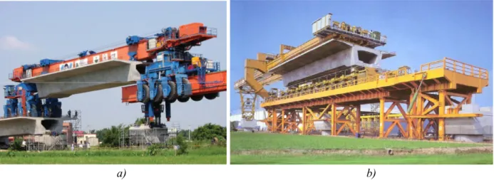
(24) Introduction. in terms of construction of conventional goods lines, connecting sea ports to the Portuguese and Spanish hinterland. Recently, prefabrication has played an important role in the construction of railway bridge decks. In France and Spain, different prefabricated solutions with I-shaped or U-shaped girders have been adopted (Figure 1.1). In France, several viaducts were constructed, in the line LGV EstEuropéenne, using precast I-shaped girders (Vavel 2004). The spans were made continuous, but continuity prestress was not employed. In these structures, the span length is, in general, equal to 22.5 m. Each viaduct is divided into a succession of various elementary viaducts separated by expansion joints, so that the length of each continuous deck is approximately equal to 90 m (four continuous spans of 22.5 m). In Spain, U-shaped girders have been widely employed in the construction of bridge decks with one or more box girders (Aparicio 2004; Sobrino 2003). Both isostatic spans and continuous solutions have been employed. Continuity connections have been built with continuity prestress or, alternatively, using only passive reinforcements.. a). b). Figure 1.1 –Railway bridge decks made with precast girders: a) viaduct in the French line LGV Est-Européenne, built with I-shaped girders (Structurae 2011a); b) viaduct in the Spanish line Madrid-Barcelona, made with U-shaped precast girders (Aparicio 2004).. In Italy, more than 90% of new railway viaducts included in the high-speed network were made with simply-supported prestressed concrete decks. Most of these were built with precast elements (Evangelista and Vedova 2004). Precast I-shaped and U-shaped girders, similar to the ones employed in France and in Spain, were also employed. However, other solutions were also adopted. Precast box girders, connected through a narrow strip of cast-in-place concrete, were also employed (Figure 1.2a). In some structures, such as the Piacenza viaduct, very heavy precast elements were used, with a total weight of 970 t per beam (Figure 1.2b). In this case, each span is formed by a single prefabricated element (Evangelista and Vedova 2004; Miotti et al. 2003).. 2.
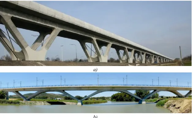
(25) Chapter 1. Similar solutions, with very heavy prefabricated elements that form a single span, were also employed in Taiwan (Figure 1.3), with typical spans of 35 m (Fritsch 2003). The full span precast method has also been used in South Korea, with typical spans of 25 m and precast elements with a total weight of ~600 t per beam (Kauffman 2001).. a). b). Figure 1.2 – Precast solutions for railway bridge decks in Italy: a) deck composed by two precast box girders; b) precast bi-cellular box girder that constitutes a single span, in Piacenza viaduct (Evangelista and Vedova 2004).. a). b). Figure 1.3 – Railway viaducts in Taiwan, each span being made with a single prefabricated element: a) construction with erection equipment by VSL (2010); b) construction with erection equipment designed by Wiecon (2011).. Precast U-shaped girders have also been used in the construction of high-speed lines in Belgium (Couchard and Detandt 2003; Kaiser 2005). In this case, inclined prefabricated columns, monolithically connected to the girders, were used in order to provide the structure with great horizontal stiffness in the longitudinal direction (Figure 1.4a). Similar solutions have also been adopted in Spain (Figure 1.4b).. 3.
(26) Introduction. In Portugal, precast solutions were also adopted in the design of viaducts for the line linking Lisbon to the Spanish border. In the section from Poceirão to Caia, continuous viaducts made with U-shaped precast girders, with typical spans of 30 m, 35 m and 40 m, were generically adopted (ELOS and LGV 2010). The total length of double-track precast viaducts in the highspeed line amounts to 8.4 km. The length of single-track precast viaducts in the conventional goods line, which goes side by side with the high-speed line along part of the way, reaches a total of 5.1 km.. a). b) Figure 1.4 –High-speed railway bridges made with precast U-shaped girders and inclined columns: a) Battice Viaduct in the line linking Brussels to Cologne (Structurae 2011b); b) Portal Viaduct in Cadiz (image gently provided by Carlos Fernandez Casado, S.L.).. In view of the relevance of prefabricated solutions in the construction of modern railway bridge decks, and taking into account the foreseeable investments in the construction of railway lines in the near future, this thesis aims to contribute to the knowledge about the real performance of these structures, and also to give a contribution in terms of numerical methods for analysis of this type of construction. The relevance of research devoted to the study of typical precast solutions for bridge decks was pointed out by Calavera (fib 2004). This author denotes that most publications regarding case studies and guidance on design and execution of precast bridges generally focus on the most spectacular structures, with very large spans and challenging execution conditions. However, the bulk of the bridge market concerns ordinary bridges with moderate spans. Calavera (fib 2004) also points out that the knowledge about modern precast bridges among authorities and designers is often limited, which motivates several prejudices. 4.
(27) Chapter 1. In this work, special attention is also paid to continuous precast bridge decks without continuity prestress. As shown before, this construction technique has recently been employed in France and in Spain. One of the specificities of this type of structure lies in the absence of continuity prestress in structures whose spans are, in some cases, longer than 30 m. The adoption of continuous precast decks without continuity prestress is strongly motivated by economic and construction factors. When compared to solutions with continuity prestress, the latter is usually less cost-effective and makes the construction procedure more time consuming and complex. However, if continuity prestress is not employed, cracking can occur in the vicinity of continuity supports. Cracking gives rise to modifications of the structural stiffness, and consequently, affects the structure response to the passage of high-speed trains. Therefore, the development of feasible analysis methodologies for calculation of the stiffness decrease in cracked structures subjected to cyclic loading is of interest. Moreover, crack openings must be limited to given threshold values, so that the durability of the structure is not impaired. The development of analysis methodologies for computation of residual crack openings in structures subjected to important cyclic loads is, therefore, needed. Another specificity of bridge decks built with precast girders has to do with the reduced thickness of the various deck components, which implies that their fatigue behaviour should be analysed in detail. On the one hand, thanks to the adoption of light structures, the traffic (cyclic) loading represents a significant percentage of the total loading. As the importance of cyclic loading increases, fatigue verifications become more critical, when compared to other limit states. On the other hand, precast girders typically have thin webs, subjected to important shear forces, which makes them sensitive to the fatigue phenomenon. Moreover, girder webs are also subjected to important transverse (out-of-plane) bending moments, which must also be taken into account in fatigue analyses. In the case of continuous precast girders without continuity prestress, the occurrence of cracking gives rise to an increased relevance of the fatigue phenomenon, because higher stresses occur in cracked structures. Furthermore, a recent survey carried out by the ERRI Committee D216 (2002) concluded that there is a need for further studies into the application of various existing fatigue analysis procedures for railway bridge decks. Therefore, the development of analysis methodologies for fatigue analysis of railway bridge decks appears to be of interest. Special attention has to be paid to the combined effects of in-plane shear and out-of-plane bending in precast girder webs. The specificities of bridge decks built with precast elements motivated extensive laboratorial experiments in France. In this country, fatigue tests were carried out at the CERIB (Chefdebien 1998) for evaluation of the fatigue behaviour of the adopted construction procedure, which comprehends continuous bridge decks without continuity prestress, built with precast I-shaped 5.
(28) Introduction. girders. Continuous beams, made up of two precast girders with spans of 5.35 m, were subjected to cyclic loading, simulating the working life of approximately 100 years on a high-speed TGV line. Also, precast structures undergo significant stress redistributions, owing to the modification of the structural system during construction and concrete deformations due to creep and shrinkage. The validation of numerical methodologies for calculation of long-term stress redistributions, through the comparison with experimental results obtained in real structures is, at the present time, quite limited. Therefore, the additional validation of long-term analysis procedures, by using monitoring results from the observation of real structures, is of interest. Both the concrete delayed deformations and the girder ages at the time the continuity is established are subjected to an important variability (i.e., accurate predictions of their actual values can hardly be made at the design stage). Therefore, a significant variability is also associated to the calculated long-term stresses. For that reason, the development of analysis methodologies for calculating the variability of the structure response, taking into account the variability of concrete delayed deformations and construction timings, also appears to be of interest.. 1.2 Objectives and main contributions The main purpose of this thesis consists of the development and validation of numerical methodologies for the analysis of continuous precast railway bridge decks. Special attention is devoted to continuous structures without continuity prestress. New methodologies are proposed for: . numerical evaluation of the stiffness decrease and residual crack openings at the continuity connection due to cyclic loading;. . fatigue analysis of girder webs subjected to in-plane shear and out-of-plane (transverse) bending.. Numerical methodologies for evaluation of long-term redistributions of stresses in continuous bridge decks built with precast girders are also validated through the comparison with experimental results.. The first part of the present work focuses on the development of a numerical model for analysis of the cyclic behaviour of reinforced and prestressed concrete elements after cracking. Various premises were taken into consideration during the conception of the model. The model should be 6.
(29) Chapter 1. able to analyse the response of structures subjected to variable-amplitude load histories. Realistic constitutive models should be used to describe the cyclic behaviour in terms of stress-crack opening relationship and bond stress-slip response. The model should also provide realistic values for both the stiffness decrease and the residual crack openings in structures subjected to cyclic loading. Furthermore, the model should be feasible and robust for application in design practice. The adopted analysis approach consists of the discretization, through the finite-differences technique, of a reinforced concrete element comprised between the cross section where a crack occurs and the closest cross section where the slip between the tensile reinforcement and the surrounding concrete is null. In the transverse direction, the cross-section is decomposed into horizontal layers. Applied actions can include axial forces and plane bending. The influence of concrete shrinkage is taken into account. The adopted constitutive models to describe the bond stress-slip behaviour and the normal stresscrack opening relationship consist of modified versions of models reported in the literature. Modifications were introduced in order to solve convergence difficulties, and also to improve the agreement with experimental results. The developed model was validated through the comparison with experimental results available in the literature for prestressed concrete ties and reinforced concrete beams subjected to cyclic loading.. The second part of this thesis focuses on the fatigue behaviour of reinforced and prestressed concrete railway bridge decks. Alternative procedures for fatigue analysis of railway bridge decks are presented. The specificities and the field of application of each analysis procedure are presented, aiming at contributing to the knowledge about the fatigue behaviour of railway bridge decks and about methodologies for fatigue analysis of this type of structure. Software for fatigue analyses according to the damage accumulation method (the most detailed analysis procedure among the ones considered in this work) was developed, so that the fatigue damage associated to any traffic scenario can be calculated. A feasible procedure for taking into account the lateral degradation of train axle loads through rails, sleepers and ballast was also implemented. One of the specific objectives of this work consists of the development of a numerical methodology for fatigue analysis of girder webs, considering the combined effect of in-plane shear and out-of-plane (transverse) bending. This task is considered to be relevant owing to the 7.
(30) Introduction. limited amount of information available in the literature about this theme, and also owing to the reduced thickness of typical precast girder webs (which makes them sensitive to fatigue). The developed methodology is based on the damage accumulation method, and can, therefore, be used to calculate the fatigue damage caused by any traffic scenario. A specific algorithm for calculation of the stress history applied to the stirrups and to the concrete compression struts was conceived. This methodology was validated through the comparison with experimental results reported by Gaspar (2003).. The third part of the present thesis focuses on the long-term behaviour of continuous bridge decks built with precast girders. The main purpose of this task consists of the validation of numerical methodologies for calculation of long-term redistributions of stresses and bending moments. This validation is carried out by comparing numerical calculations with experimental results observed in a real viaduct. The structure under analysis is the South Access Viaduct to the Lezíria Bridge in Portugal, which has been monitored since the beginning of the construction. This experimental work has been carried out by NewMENSUS (2011) and LABEST (2011). The specific objectives of this task comprehend: . the evaluation of the adequacy of finite-element viscoelastic phased analyses to predict the real behaviour of this kind of structure;. . the evaluation of the errors associated to simplified analyses based on limited information about the concrete properties and the sequence of construction;. . the evaluation of the adequacy of probabilistic analyses based on Monte Carlo simulations to calculate tolerance intervals that contain the actual results (stresses, strains or bending moments) with a certain confidence level, taking into account the variability of creep, shrinkage and construction timings;. . contribute to the knowledge on the long-term behaviour of this kind of structure.. In the last part of this thesis, the developed and validated analysis methodologies are applied to the analysis of a real precast railway bridge deck, included in the Spanish line linking Alcácer to Valencia. This structure is composed of four continuous spans (interior spans of 33.5 m and end spans of 26.5 m) without continuity prestress. The main purposes of this task are as follows: . to illustrate the application of the developed and validated numerical methodologies, which allow the detailed analysis of critical aspects of the structural behaviour of this type of structure;. 8.
(31) Chapter 1. . to contribute to the knowledge about the structural behaviour of this bridge type.. 1.3 Organization of the text This thesis is divided into seven chapters, whose content is briefly summarized in the following paragraphs. The present Chapter 1 presents the main motivations for the development of this thesis, describes its main objectives, and outlines the organization of the text. Chapter 2 is dedicated to the numerical analysis of the cyclic behaviour of reinforced and prestressed elements after cracking. This chapter starts with a review of constitutive models to describe the bond stress-slip relationship and the normal stress-crack opening relationship in structures subjected to cyclic loading. Then, it presents the state of the art in terms of numerical models for analysis of cracked, reinforced and prestressed concrete elements subjected to cyclic loads. After that, the developed numerical methodology is described. Finally, the validation of that methodology is made through the comparison with experimental results reported in the literature. Chapters 3 and 4 are dedicated to fatigue analyses of railway bridge decks. Chapter 3 starts with a brief presentation of the fatigue behaviour of concrete, steel and reinforced concrete structures. Then, a critical review of alternative methodologies for fatigue analysis of railway bridge decks is presented. Special attention is paid to bridge decks included in high-speed lines. Chapter 4 focuses on the fatigue analysis of girder webs subjected to in-plane shear forces and out-of-plane (transverse) bending moments. Firstly, the adequacy of truss models for stress calculations in fatigue analyses of beams subjected to in-plane shear is assessed by comparing numerical calculations with experimental results reported in the literature. Then, the developed procedure for stress calculations considering the combined effect of in-plane shear and out-ofplane bending is described. Then, this procedure is validated through the comparison with experimental results. Even though this chapter focuses on fatigue analyses, available methodologies for ultimate limit state analyses (considering the interaction between in-plane shear and transverse bending) are identified. The applicability of the developed methodology to problems of shear between web and flanges is also discussed. Chapter 5 is dedicated to the analysis of the long-term behaviour of precast continuous bridge decks, considering the influence of concrete delayed deformations and phased construction. A recently constructed viaduct is adopted as a case study. This chapter starts with the description of 9.
(32) Introduction. the structure and the monitoring system. Then, the experimental results are compared with the ones calculated by means of finite-element analyses. The results of calibrated analyses – in which the material properties and the sequence of construction are defined taking into account data gathered during the construction – are compared with “blind” analyses – based only on the information that is usually available at the design stage. Finally, the variability of the structure response, due to the uncertainty associated to the quantification of concrete delayed deformations and construction timings, is assessed by means of a probabilistic analysis. In Chapter 6, the previously developed numerical methodologies are applied to the analysis of a real railway bridge deck built with precast U-shaped girders. The structure is described, and the external loads considered in this study are presented. Then, the long-term redistributions of stresses and internal forces are evaluated. Following this, the fatigue behaviour of both the girder webs and the deck slab is analysed and discussed. Finally, the consequences of cracking, owing to the absence of continuity prestress, are discussed. Chapter 7 presents the main conclusions of this work, and summarizes some future research topics.. 10.
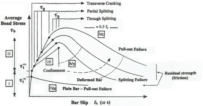
(33) Chapter 2 Numerical analysis of the cyclic behaviour of RC elements after cracking. 2.1 Introduction Stiffness is one of the parameters that most affect the dynamic behaviour of railway bridge decks. Even though the maximum mid-span accelerations are not significantly affected by the stiffness of the structure (ERRI D214 1999b), the dynamic displacements and the dynamic enhancement of internal forces depend considerably on the structural stiffness (ERRI D214 1999b). Moreover, the critical speeds at which resonance effects occur also depend on the natural frequencies of the structure which, in turn, are influenced by its stiffness. Therefore, the accurate prediction of structural stiffness plays an important role in the analysis of railway bridge decks, particularly in the case of structures that are not fully prestressed, in which the admissible cracking frequently causes significant reductions in structural stiffness. The ERRI Commission D214 (1999a) conducted a survey on the different methods in national codes for calculating bridge stiffness and found different practices for taking into account the stiffening effect of concrete in tensile zones. Based on this survey, this commission identified the following research needs: . the development of methods for calculation of the stiffness of cracked reinforced concrete in slabs;. . the development of methods for calculation of the stiffness of composite bridge decks in hogging zones over intermediate piers; 11.
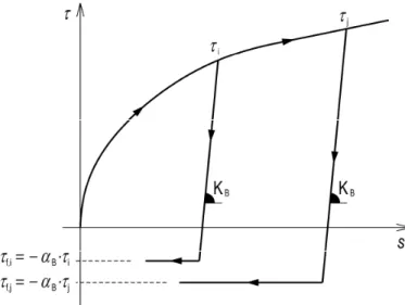
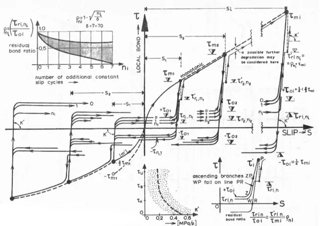
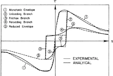
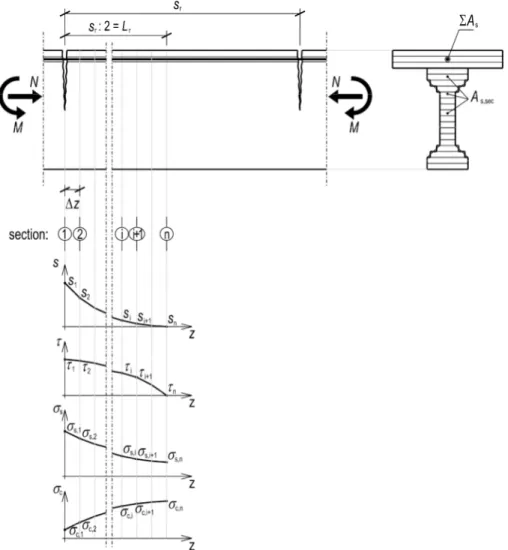
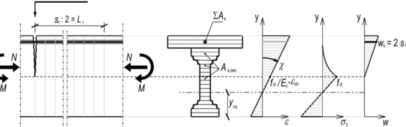
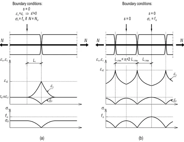
(34) Numerical analysis of the cyclic behaviour of RC elements after cracking. . the understanding of the differences in the structural response for short term static loadings and the behaviour at frequencies corresponding to the dynamic response, for different loading amplitudes.. Crack openings are also significantly affected by traffic loading (Rotilio 1998). In the case of railway bridge decks, traffic loads have important values, and consequently, residual crack openings (after removal of live loads) can be significantly affected by the maximum applied live loads. Therefore, cyclic loading should be considered in the calculation of crack openings for durability verifications, particularly in the case of reinforced concrete (RC) structures sensitive to these effects (e.g. continuous railway bridge decks without continuity prestress). However, the Eurocodes fail to do that, as will be shown in Chapter 6. Feasible numerical tools for taking into account the influence of live loads in the calculation of residual crack openings are therefore needed. The aforementioned reasons were the motivations for the development of a numerical methodology for the analysis of the cyclic behaviour of reinforced concrete members after cracking, which was, in turn, validated through the comparison with experimental results. The methodology was devised so that it could comply with the following principles: . it should be able to analyse the structural response under the effect of a load history composed by variable-amplitude load cycles;. . realistic constitutive models should be used to describe the concrete cyclic behaviour, with respect to the stress-crack opening and the bond stress-slip relationships; these models should correctly define the non-linear unloading and reloading trajectories of the material behaviour;. . the model should provide realistic values for both the stiffness decrease due to cracking and the residual crack openings due to permanent and variable loads;. . the feasibility and the usability of the model should be a matter of concern, so that this methodology could be used in practice.. The proposed analysis approach consists of the discretization, through the finite differences technique, of a RC element comprised between a cross section where a crack occurs and the closest cross-section where the slip between the tensile reinforcement and the surrounding concrete is null (at the stabilized cracking stage, this cross-section is located halfway between two consecutive cracks). The solution is found iteratively by employing the bisection method. In the transverse direction, the cross-section is decomposed into horizontal layers. The influence of concrete shrinkage is taken into account. This methodology was based on the work of several researchers, identified below, who adopted the same type of model with different purposes. The adopted constitutive models were based on the literature review that is summarized below, too. 12.
Imagem
+7
Documentos relacionados