Universidade do Minho
Escola de Engenharia
Daniel Nascimento Cadete
From Natural Language Requirements to
Formal Descriptions in Alloy through
Boilerplates
Universidade do Minho
Escola de Engenharia
Daniel Nascimento Cadete
From Natural Language Requirements to
Formal Descriptions in Alloy through
Boilerplates
Dissertação de Mestrado em Engenharia de Informática
Trabalho efectuado sob a orientação do
University of Minho School of Engineering
From Natural Language Requirements to Formal
Descriptions in Alloy through Boilerplates
Daniel Nascimento Cadete
Informatics Department - University of Minho
January 31, 2012
Acknowledgements
I would like to thank my supervisor, José Nuno Oliveira, for all the help, guidance and inspiration, for all the time spending discussing ideas for this dissertation and for allowing me to see software development in a different perspective. Working with him was an inspiring task and something that I will never forget. I strongly believe that his vision of software and mathematics together, can shape the future of software development.
To my colleagues from Braga, João Martins, André Pedro, Manuel Costa, Nelson Gonçalves, João Bordalo, Raquel Ribeiro, and Francisco Ribeiro, I would like to thank for all the relaxing moments and for all the chats which greatly inspired this dissertation.
To my friends João Vieira, Nuno Santos, Bruno Almeida, Ana Sequeira, Samuel Martins, Cátia Conceição, João Palma, Cristel Domingos, Cátia Esteves I would like to thank for all the support, hours of laughing and the countless times you have made me move forward to complete this dissertation.
To Critical Software and particularly José Miguel Faria I would like to thank for ideas, back-ground and support which significantly improved this dissertation. Thanks are also due to the Educed team and particularly André Passos, for their support and interest on the results of this dissertation. Seeing one’s research absorbed by industry makes the work extremely fulfilling. To EVOLVE/QREN project I would like to thank for the financial support which partially funded this research through a research grant.
Many thanks to all my family who put expectations on me and always helped me move forward. Specially to my beautiful niece Matilde, whose smile and those big hugs make me want to be near her all the time.
To my father, mother and sister, I dedicate this dissertation. During all my life, you have been my inspiration and my idols, you have taught me how to overcome challenges and work hard to get the things I want in life.
Resumo
Os métodos formais são normalmente aplicados por especialistas nas fases finais do desen-volvimento de software. A sua aplicação visa identificar erros de programação, reduzindo assim a probabilidade de uma falha futura. Tipicamente, os erros que se encontram prendem-se com má interpretação de requisitos e não má programação. Cada vez mais os documentos de req-uisitos tratam de termos complexos e fora do conhecimento do programador, o que leva a mais erros de interpretação e consequentemente a um aumento dos custos de execução de um pro-jeto de software. A utilização de métodos formais poderia minimizar estes custos, caso eles fossem utilizados não para verificar código, mas sim para verificar requisitos. No entanto, muitas empresas evitam a utilização de métodos formais, devido ao custo elevado da sua aplicação. Os programadores ou engenheiros de requisitos não conseguem aplicar métodos formais de forma eficiente sem terem formação prévia e específica na área, o que implica a contratação de especialistas em métodos formais.
Nesta dissertação são apresentados métodos que visam aproximar os métodos formais da escrita dos requisitos. Para tal, a modelação formal é utilizada não para verificar código, mas para verificar a escrita de requisitos. Inicialmente é apresentado um standard para a criação de modelos, que faz uma correspondência direta entre cada requisito e o seu modelo formal. Este standard é suportado por uma ferramenta que, entre outras coisas, gera de forma automática representações gráficas dos requisitos através dos seus modelos. Posteriormente é apresentada uma conexão entre templates de requisitos (requirements boilerplates) e modelos Alloy. Esta conexão permite a criação de modelos formais de forma automática, sem necessidade de um especialista. Isto reduz drasticamente o custo de utilização de métodos formais. Apresenta-se igualmente o começo de uma álgebra que permite agregar estes templates. Esta agregação permite que um engenheiro de requisitos escreva o seu documento de requisitos através de templates e no fim tenha de forma automática o modelo formal de todos os requisitos.
Quando se está a modelar um documento de requisitos em Alloy e a certo ponto aparecem requisitos com restrições temporais explícitas, é necessário recriar todo o modelo numa ferra-menta que permita essa modelação (ex: Uppaal). Este processo está sujeito a erros, porque esta transformação é manual e altamente dependente da interpretação de quem está a modelar. Nesta dissertação é apresentado um método que permite a geração automática de um modelo Uppaal a partir de um modelo Alloy. Esta transformação permite que a qualquer ponto da mod-elação em Alloy, se crie o modelo Uppaal correspondente e se especifiquem as propriedades temporais.
Abstract
Formal Methods are usually applied by specialists in the final phases of software development. They aim to identify programming errors, and through that reduce the probability of a future failure. Usually, errors are more related with misinterpretation of requirements than with bad program-ming. More than ever, requirements documents deal with complex terms, which programmers aren’t familiar with, resulting in an increase of misinterpretation of requirements and increasing the costs of the execution of a software project. The use of formal methods could reduce these costs, if properly used to verify requirements and not source code. However, most companies avoid using formal methods due to high costs associated with formal methods application. Pro-grammers or requirements engineers can’t apply formal methods efficiently without previously having specific training, which implies hiring expensive specialists in formal methods.
This dissertation presents methods which aim to bring formal methods closer to requirements descriptions. For such, formal modeling is used to verify and validate the descriptions of require-ments, and not source code. Initially it’s presented a standard to create formal models, which makes a direct correspondence between each requirement and its model. This standard is sup-ported by a tool which, among other things, automatically generates graphics representations of requirements using its models. Afterwards it’s presented a connection between requirements boilerplates and Alloy models. This connection allows to generate formal models in an auto-matic fashion, without the need of a specialist. This drastically reduces the costs of using formal methods in software projects. It’s also presented the beginning of an algebra which allows to aggregate these templates. This aggregation allows one to write its requirements documents throught boilerplates and at the end have the complete model of all requirements, for free.
When one is modeling a requirements document in Alloy and at some point appears require-ments with explicit temporal restrictions, it’s necessary to recreate the whole model in a tool which allows that kind of specification (eg. Uppaal). This process is highly error prone, because it’s a manual transformation and highly dependent on the interpretation of who is modeling. In this dissertation it’s presented a method which allows to automatically generate an Uppaal model from an Alloy model. This transformation allows that at any point in the requirements document, the requirements engineer can generate the correspondent Uppaal model and there specify the temporal properties.
Contents
List of Acronyms k List of Figures m List of Tables o 1 Introduction 1 1.1 Requirements Engineering . . . 2 1.2 Formal Methods . . . 51.3 Formal Methods and Requirements Engineering . . . 6
1.4 Aims of the dissertation . . . 7
1.5 Document Structure . . . 7
2 Formal Methods Tools 9 2.1 Alloy . . . 9
2.1.1 Modeling Idioms . . . 17
2.1.2 Alloy and Relational Calculus . . . 19
2.2 Uppaal . . . 23
2.2.1 Specification . . . 23
2.2.2 Verification . . . 24
2.3 Summary . . . 25
3 Requirements Engineering Assisted by Formal Methods 27 3.1 Introduction . . . 27
3.2 Methodology . . . 30
3.3 Tool Support . . . 35
3.4 Summary . . . 39
4 Case Study : Partitioning Microkernel 41 4.1 Document Structure . . . 41
4.2 Requirements Modeling . . . 43
4.3 Summary . . . 54
5 From Boilerplated Requirements to Abstract Models 55 5.1 Introduction . . . 55
5.2 Boilerplates meets Alloy. . . 56
5.3 Boilerplates Repository . . . 58
6 From Alloy to free Uppaal models 63 6.1 Introduction . . . 63 6.2 Methodology . . . 64 6.3 Tool Support . . . 72 6.4 Final Considerations . . . 76 6.5 Summary . . . 81
7 Conclusions and Future Work 83 Bibliography 87 Index 92 A Partitioning Kernel Modeling 95 A.1 Scheduling Instance. . . 109
Acronyms
API Application Programming Interface. CC Common Criteria.
CMS Configuration Management System. DFA Deterministic Finite Automaton. FMTR Formal Methods Tool Repository. GUI Graphical User Interface.
IFIP International Federation for Information Processing. LCS Life-Critical System.
LHS Left Hand Side.
NATO North Atlantic Treaty Organization. NL Natural Language.
OOP Object Oriented Programming. PIFP Partition Information Flow Policy. RB Requirements Boilerplates. RE Requirements Engineering. RHS Right Hand Side.
SAT Boolean satisfiability problem. SPK Secure Partitioned Kernel. UML Unified Modeling Language. VSR Verified Software Repository. XML Extensible Markup Language.
List of Figures
2.1 Make directory operation . . . 17
2.2 Running theLightBulbmodel in global state idiom. . . 19
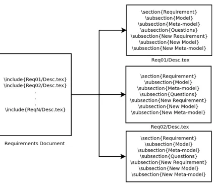
3.1 A Requirements Document . . . 36
3.2 Tool Pipeline . . . 36
3.3 Macros for writing models. . . 37
4.1 Partitioning Microkernel . . . 42
4.2 Partition Model . . . 44
4.3 A model instance . . . 44
4.4 Partition Model . . . 45
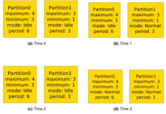
4.5 Partitions Evolution over Time . . . 46
4.6 Partitions Evolution over Time . . . 48
4.7 Process Model. . . 50
4.8 Partitions Evolution over Time . . . 53
6.1 Traces of the River Crossing Puzzle . . . 66
6.2 A Set of Alloy instances. . . 67
6.3 A DFA from a set of instances. . . 68
6.4 The minimum DFA from a set of instances. . . 71
6.5 The minimum DFA of the river-crossing problem. . . 72
6.6 Tool Interface . . . 73
6.7 Alloy Instance. . . 74
6.8 Graph from an instance. . . 75
6.9 Trace of execution. . . 78
6.10 DFA Generated without abstract interpretation. . . 78
6.11 Correct DFA Generated with the tool. . . 79
6.12 River Crossing with Real-Time Restrictions. . . 81
List of Tables
1.1 Why software projects fail . . . 3
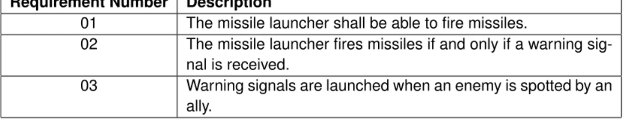
3.1 Missile Launcher Requirements . . . 27
Chapter 1
Introduction
Software has gained a prominent place in mankind history. It is today an essential part of ev-ery service, business process or research activity. Software usage has proliferated and is om-nipresent not only in companies and universities but also in the every day life of the anonymous citizen: in cars, mobile phones, bank ATM systems, home computers, TV sets, houses, and so on.
Since the first computer program by Ada Lovelace to the highly complex software systems of today which control nuclear power-stations, maintain airplanes flying or coordinate complex financial operations across the globe, the process of software construction has undergone an impressive evolution. However, under such rapid growth in both complexity and demand for soft-ware, programmers have become unable to deliver 100% safe software systems, meaning that quality is hard to achieve both in the development process and in the end product.
Such an embarrassing situation dates back to the 1960s, when the world first witnessed what became known as the Software Crisis. This was the first evidence that the archaic development methods of those times were inefficient and resulted in poor quality, highly error prone software often offering more costs than benefits. Under the urgent need to change this situation, theNorth Atlantic Treaty Organization (NATO) organized a Software Engineering Conference in 1968 at Garmisch, Germany where academics from several universities, staff from software companies and other contributors from the civil sector addressed issues such that the design, production, implementation, distribution and service of software [65]. In this conference the phrase “Soft-ware Engineering” was coined to reflect the need for soft“Soft-ware manufacture being based on solid foundations:
In late 1967 the Study Group recommended the holding of a working conference on Software Engineering. The phrase ‘software engineering’ was deliberately chosen as being provoca-tive, in implying the need for software manufacture to be based on the types of theoretical foundations and practical disciplines, that are traditional in the established branches of engi-neering. (Quoted from [65].)
Provocative or not, the need for sound theoretical foundations has clearly been under concern since the very beginning of the discipline.
TheNATO Conference of 1968 triggered the development of a series of methods and guide-lines which significantly improved software quality. Business could now rely on machine support without fear that at any moment the software would start to fail with consequent massive losses. Software development was structured in a sequence of formal phases, usually starting with in-formal meetings where clients exposed their needs and requirement engineers tried to gather a
sketch of what the system should be able to do and in which conditions. The outcome of such meetings would be grouped and refined until all requirements were written inNatural Language (NL)and put together into a so-called requirements document. These requirements documents could then be passed to the development team who would be charged thereupon with developing a system that should meet the requirements written in the document.
In this way, requirements engineering emerged as one of the most important areas in the software industry. After theNATO conference further investigation was carried out by an ever larger number of researchers, industry and universities. In 1995, theInternational Federation for Information Processing (IFIP)Working Group 2.9 was established, aiming at providing insights on requirements specification, interpretation and documentation. This group encompasses a num-ber of different areas in requirement engineering: formal representation and requirements mod-eling, requirement elicitation and further analysis, tools and environments to support requirement engineering, requirements for safety-critical, real-time and embedded systems, etc.
The area of IFIP2.9 which studies requirements on safety-critical and real-time systems is intrinsically related to the scope of this dissertation. Many software systems of today are systems whose failure does not result in life or money loss: one may have to restart the computer or lose a day of hard work, but hopefully one will live another day to work out the problem. However, there are software systems which cannot fail in any circumstance. A system of this kind is usually called aLife-Critical System (LCS). LCS failure or malfunction can result in death or injury to people, environmental harm or loss of great amounts of money [7].
PreventingLCSs from failure or malfunction has became extremely important and the history of 20th and 21th century is full of catastrophes caused byLCSmalfunction. On 4 June 1996 the Ariane rocket crashed 37 seconds after launch. According to [57] the cause for its crash was an integer overflow arising from bad software design practice. The Denver International Airport main advance would be its top technology in an automated baggage handler, but software problems delayed the airport opening by 16 months [66]. All these events (and many others found in literature [32,60,12]) have resulted in millions of dollars spent to resolve failures and sometimes in human life losses.
As the software industry started to face new challenges, universities and software companies started to invest in new approaches to maintain the strict requirements ofLCS. Some invested in methods in the area of software engineering, trying to improve existing methods. Others discov-ered new methods ensuring that systems wouldn’t fail or that the probability of failure is residual [64,52,11]. Other invested in mathematical theories to prove or increase the confidence that soft-ware system won’t fail based on sound mathematical proofs. This is what the scientific community recognizes as Formal methods [14].
1.1
Requirements Engineering
Ian Sommerville presents a widely accepted definition for software engineering in [78]:
Software Engineering is an engineering discipline that is concerned with all aspects of soft-ware production from the early stages of system specification to maintaining the system after it has gone into use.
Software engineering thus appears across all phases of software development. Software engi-neers try and improve this discipline every day so as to discover new methods of analysis. In order to improve software quality one needs to know first and foremost why systems fail or don’t
do what they are supposed to do. The Standish Group present in [79] a number of factors for software failure, given in Table1.1.
Table 1.1: Why software projects fail
Factors %
Incomplete Requirements 13.1 Lack of User Involvement 12.4 Lack of Resources 10.6 Unrealistic Expectations 9.9 Lack of Executive Support 9.3 Changing Requirements & Specifications 8.7 Lack of Planning 8.1 Didn’t Need it Any Longer 7.5 Lack of IT Management 6.2 Technology Illiteracy 4.3
Other 9.9
Inspection of this table shows that poor use of technologies is not a main factor for software project failure, but rather incomplete requirements, which is the factor standing at the top. So soft-ware engineering had to find “new engineering” inside itself: requirements engineering. Laplant defines requirements engineering in [58] as:
Requirements engineering is the process of eliciting, documenting, analyzing, validating, and managing requirements.
The term requirement usually means a service the system should provide. Clearly, by improv-ing the quality of requirements one not only improves the quality of target software system but also does so at a much lower cost when compared to improving the other phases in development and maintenance, where (bad) design decisions have been committed into the system already.
According to [78], requirements can be divided into:
• User Requirements - Statements in NL telling what services the system is expected to provide and under which circumstances.
• System Requirements - System’s functions, services and operational constraints in detail. Both system and user requirements shouldn’t be directly delivered to the development team without passing through a series of stages which aim to improve the quality and understanding of requirements. First of all, they should be elicited through a number of different techniques such as group elicitation, prototyping, model-driven techniques, etc. This elicitation phase 1 aims to find out which main problems need to be solved, how the system will fit with the existing organization and the stakeholders [33] and so on.
After the elicitation phase, requirements should be modeled and analyzed. Typically in this phase, the requirements are represented in some abstract form. One finds in [67] find different types of modeling that one submit requirements to:
1
The word “elicitation”, which comes from the Latin “elicit” (‘draw out by trickery or magic’) means drawing forth something that is latent or potential into existence.
• Enterprise Modeling - Organization structure and how the system will interact with it.
• Data Modeling - Analyze how the system data will be manipulated and kept.
• Behavioral Modeling - Interactions of the stakeholders with the system.
• Domain Modeling - How the system will interact with the world around it.
• Non-Functional Requirements Modeling - Quality objectives that the system should meet. It is important to define from the early stages of the project who will use and read require-ments. In most projects, requirements are used by several people:
• User - Someone who uses and tests the final system.
• Systems Engineer - Someone who focuses on the design and management of the project life cycle.
• System Designer - Someone who designs the architecture, components, modules, inter-faces of the software.
• Programmer - Someone who writes the software.
• Tester - Someone who writes and performs software tests.
Requirements are usually written inNLand they hardly can be written in other format due to the fact that all people mentioned above, and participates in the software development should be able to easily understand any requirement [1]. BecauseNLis ambiguous and imprecise, require-ments engineers have tried to find ways to improve the quality of requirerequire-ments without writing them in other (eg. formal) way. A major advance in achieving higher quality requirement textual descriptions is to consistently write each requirement following aRequirements Boilerplates (RB).
Requirements boilerplates are textual templates of the form:
The <Stakeholder> shall be able to <Capability>
The idea is to cast arbitrary requirements into such templates, as a means to ensure that one is not writing possibly ill-formed or difficult to understand free text, but rather a piece of text which as been used by others and proved effective and implementable before. Faced with a requirement such as ”The Operating System can schedule processes“, one can write the requirement by instantiating the above boilerplate: TheOperating System shall be able to Schedule Processes.
Requirements boilerplates play a major role in the approach to requirements engineering put forward in this dissertation. A detailed account of requirements boilerplates will be given in Chapter5.
Another important concept in requirements engineering is traceability. Traceability is de-scribed in [34] as
”Requirements traceability refers to the ability to describe and follow the life of a requirement, in both a forwards and backwards direction (i.e., from its origins, through its development and specification, to its subsequent deployment and use, and through all periods of on-going refinement and iteration in any of these phases).”
Requirement traceability is important because requirements change all over the development cy-cle of a software project. Keeping track of those changes helps bringing up requirement quality and justifies why clients want particular requirements. In design process, traceability helps in justi-fying design options, with a complete history of the design process and its changes. It is essential for testers, because test cases are designed to test specific sets of requirements. Whenever a requirement changes, testers know exactly which changes need to be made in their test suites in order to cover the changed requirements [74].
Requirements traceability is usually achieved using frameworks. Researchers have put to-gether several frameworks which aim to improve traceability using both manual an automatic tasks. However, there is today an increasing need for automatic frameworks catering for au-tomatic requirement traceability [15]. Chapter 3 will present a method and a tool which helps in requirement traceability using formal models and a standard layout for writing and analyzing requirements.
1.2
Formal Methods
Above it was mentioned that, after the elicitation phase, requirements should somehow be mod-eled and analyzed. Formal Methods are techniques that use mathematics in the modeling, mak-ing it possible not only to specify but also to verify the design, be this hardware or software. A method is formal if it has precise mathematical foundations that enable the definition of proper-ties like consistency, completeness, specification, implementation and correctness [81]. Formal methods usage in software systems can be divided into specification and verification.
Specification is the process whereby a system and its desired properties are formally de-scribed. Usually, the important properties of a system are the behavioral ones. To specify a system one needs to write such properties in a precise manner, allowing one to gain a deeper understanding of the system and to discover design flaws, inconsistencies, ambiguities and in-completeness. The specification also provides a useful communication between the client, de-signer, programmer and tester [35].
There are several methods such as Z [82], VDM [49] and Larch [35] which cater for the formal specification of sequential systems. In such methods the system (machine) states are mathe-matical entities like sets, relations and functions; state transitions are specified by pre and post conditions. Other methods, such as CCS [63] and Temporal Logic [61], enable the specification of concurrent systems where states are defined over domains and the behavior is represented through sequences, trees, traces or events.
Verification is the process of ensuring that a system satisfies the properties described in its specification. Formal Verification used maths for this, the verification consisting in proving that all properties are met. In a sense, every property rises a theorem — the assertion of its preservation in the implementation — which is discharged by proof. As already mentioned, this is common practice in safety-critical systems, which include protocols, cryptographic algorithms, software programs and kernel hardware devices [81]. This class of verification techniques is known as Theorem Proving.
Verification can still be approached by incomplete techniques such as Model Checking. Model checking is the process of building a finite model of the system and checking if a desired property holds in that model. Because such a model is a finite approximation of the final system one can never be sure that a property is valid; but can show that the property is invalid by means of counter-examples. Model checking has been widely used to verify hardware specifications and is
now being used to verify software [3].
In theorem proving both the system and its properties are expressed as formulæ in some formal system with axioms and inference rules. In order to verify a system, one has to discharge the proof of a property using the axioms of the formal system. Although theorem proving can be carried out manually, it is usually done using a computer assisted program (Theorem Prover ) helping discharge the proof. This prover can be automatic [25] or semi-automatic [4], where the user guides the program in the proof process.
Model Checking. Later in this dissertation, model checking will be shown to be at the epicenter of the approach put forward for requirement engineering in this dissertation. It therefore deserves a more detailed account. The technique invented separately by E.M. Clarke, E.A. Emerson and J. Sifakis who earned the 2007 Turing Award. The great disadvantage of model checking is the state space explosion 2 and the impossibility to specify and verify systems with infinite states. There are two approaches to the model checking problem, the Explicit State Model Checking and Symbolic Model Checking [76].
In Explicit State Model Checking the system is modeled as a finite automaton and the proper-ties are expressed in a temporal logic. An efficient algorithm is used to determine if the property is true in the automaton. With this approach, the automaton usually consists of several spaces and the verification of properties in useful time is highly related to the user’s ability to model a system with fewer state variables [62]. Symbolic Model Checking tries to overcome this weakness by us-ing Boolean formulæ to represent sets and relations that are manipulated usus-ing so-called ordered binary decision diagrams (OBDD) [62]. With this approach, systems with up to1020system can
be verified, resulting in a wider range of verifiable systems.
1.3
Formal Methods and Requirements Engineering
Formal Methods (F.M) have been used in several phases of the software development with differ-ent objectives and results [50]. In the literature one finds research aiming at usingF.Min the early phases of software development, namely in areas related with requirements engineering.
The approaches followed by [72,38,75] use formal methods to model the requirement spec-ifications and find some ambiguities in them. Although these approaches are valuable and in-teresting, little is done in order to clear up the textual descriptions of the requirements. Their main focus is on identifying ambiguous requirements and fixing them before implementation. For a requirement engineer it is not enough to identify all requirements which are bad specified, for she/he also needs to have some kind of tips or guidelines on how to re-write them, making them more clear and suitable to be implemented.
Elsewhere researchers have tried to focus on the descriptions of requirements and methods which could improve them. References [9] and [83] put forward two approaches which try and identify bad descriptions of requirements. With methods like these, requirements engineers al-ready have the possibility to identify and re-write requirements using a set of guidelines. The main disadvantage of these approaches is their lack of mathematical formalism which doesn’t shorten the gap between requirements descriptions and implementation.
2
State space explosion usually means that the number of states needed to represent the system doesn’t fit into computer memory.
Requirements engineers would much benefit from a mathematical formalism able to provide guidelines, methods or techniques that could help in rewriting the requirement’s descriptions that are ambiguous. Through mathematics, the distance from description to implementation of re-quirements would be shorter, which would be helpful in projects where rere-quirements are con-stantly changing.
1.4
Aims of the dissertation
The software industry must use tools and techniques to prevent disasters caused byLCSfailures. Formal Methods appeared in the late 1980s as a good solution to detect and prevent software bugs [14] in such systems. Although these methods have shown significant improvement on
LCS, they are often criticized because of its difficult adoption and the high costs they purport by requiring highly specialized software engineers. This happens mainly because they are applied when the system is already developed or in an advanced state of development. As Daniel Jackson puts it [42]:
Almost all grave software problems can be traced to conceptual mistakes made before pro-gramming started.
Further to applying formal methods to code analysis and synthesis, these methods should be applied to requirements. Find a serious flaw at requirement phase in an expensive project in eg. the aerospace industry, well before any development has started, much can be saved in code refactoring and bug correction. It is widely accepted that one of the main reasons for such mistakes is the use of poorly written NLrequirements descriptions [1, 23]. Following this idea, researchers started to develop techniques and tools that help software engineers to detect and correct flaws in the early phases of software development [73,48].
This dissertation aims to improve the use of Formal Methods in requirements documents with the objective to identify mistakes in such an early phase — when actually writing them (earlier than this is not possible!). F.M will be applied in order to create a mathematical foundation for requirements documents which otherwise would not exist. This mathematical foundation may be hidden from readers of requirements documents but, if used, will provide valuable contribution to the quality of the final system through the use of mathematical meaningful boilerplates.
Through F.M it is possible to achieve not only a mathematical model which is meaningful in
further phases of development but also an insight on the quality of textual descriptions of require-ments. Requirements description are bound to be written in NL because this is the language easily understood by everyone (hopefully). But it suffers from major disadvantages: it is impre-cise, ambiguous and could lead to different interpretations in the same design. A combined use of Requirement Boilerplates (RB) with theAlloymodel checker will be eventually proposed in order to add to structure and clearance of such textual descriptions.
1.5
Document Structure
The following Chapter will present the tools used throughout the dissertation and explain why they where chosen. Chapter 3presents a method which helps requirements engineers to write better requirements documents while creating formal models for them. This method is supported by a tool developed on purpose, which is also explained in the chapter. The method is illustrated
using a small example which evolves into a larger case study in Chapter4, concerning a .Secure Partitioned Kernel (SPK)
The ideas presented in these chapters are refined into Chapter 5, where a connection be-tween requirement patterns and formal models is presented. This chapter presents an interesting connection betweenAlloyand commonly used patterns to write requirements. In Chapter6,Alloy
is integrated intoUpppal, creating an automated method which connects the two worlds (relational calculus and first order logic to networks of timed automata). Finally, Chapter7concludes and presents suggestions for future work, showing new possibilities while stressing on the industrial adoption of the ideas put forward in earlier chapters.
Chapter 2
Formal Methods Tools
The formal methods community offers today several tools which support different notation styles and purposes. In the Formal Methods Tool Repository (FMTR) 1 one can see a categorized account of formal methods tools by their different features. Which such features should a tool offer in case one wishes to adopt it to support an efficient and fast method to analyze requirements descriptions and quickly provided insights on inconsistencies and ambiguities? Such a tool should be able to identify flaws (eg. by providing counterexamples), should be versatile (making it easy to re-factor specifications) and offer a good visual representation of models and use cases. The last point is important because it will allow the user to present results to non-technical staff, that is, engineers with no deep knowledge inF.M.
Looking at theFMTR table one finds such criteria in columns ”Model Checking“,”Animation / Execution”, “Graphical User Interface (GUI)`‘ and ”Refinement“. In the following section we will
presentAlloy, a tool which meets most of such criteria. This tool will play an important role in the method presented in Chapter3, allowing for a quick way to analyze requirement descriptions. In Section 2.2we will introduceUppaal, another tool offering excellent support to model real-time constraint systems. Chapter 6 will show how to transform Alloy models into Uppaal and then apply real-time constraints in an efficient fashion.
2.1
Alloy
Alloy was created by a team in the Software Design Group at MIT lead by Daniel Jackson. The main aim was bringing the benefits of model checking and the power of abstraction to the soft-ware development world. |Alloy is a language (widely inspired by Z and object modeling notions) together with an analyzer which performs automatic verification of model properties. Alloy’s math-ematical foundation is set theory (sets, relations, etc) allowing one to easily model structures like file systems, naming schemes, architectures, etc. With sets and relations, primitive data types like records or arrays can easily be expressed and analyzed efficiently [31].
Alloy’s lemma is InAlloyeverything is a relation. The tool which comes with the language is calledAlloy Analyzer and it is atypical as a model checker. What it does is the following: given a specification of the some system or problem, it transforms it into a Boolean formula and then sends this to an off-the-shelfBoolean satisfiability problem (SAT)solver2which tries to find some
1Seehttp://fmtoolsrepository.di.uminho.pt. 2
SAT is the problem of determining if the variables of a given Boolean formula can be assigned in such a way as to make the formula evaluate to true.
model that makes the formula true.[44]
Let us illustrate theAlloyapproach to software modeling through the following example: sup-pose one wishes to model a mini file system with some basic file management operations. The fictional requirements call for an operation which allows the user to navigate through the file sys-tem and two operations for creating and removing directories. The following is also required: the root directory doesn’t have a parent directory, files and directories don’t have names and one can remove any empty directory as long as the directory isn’t the root.
Below we will go through all the steps in using theAlloylanguage and analyzer. The reader will see how easy it is to model a system and how theAlloyapproach is a lightweight one, proving effective in a wide range of problems in the software development world.
Signatures. A signature inAlloyrepresents a set of atoms. A signature can be interpreted as a class (inObject Oriented Programming (OOP)terms) and (like a class) it can declare relations associated to its atoms and the creation of implicit types. In our example three signatures are readily identified:
sig File{}
sig Dir{}
sig FileSystem{}
These offer files and directories in the file system and the atoms of the signature FileSystem will represent the file system at different points in time. A real file system has a parent relation among files and directories. Knowing that both directories and files have parent directories suggests that both File and Dir be subsets of an abstract signature called (file-system) Object:
abstract sig Object {}
sig File, Dir extends Object {}
Note the two keywords in creating signatures, extends and abstract. Where declaring a sig-nature as extends of a top-level sigsig-nature, this means that it will be a subset of the top-level signature (in the above: File and Dir are subsets of Object). The sets created by signatures File and Dir are completely disjoint. By declaring a signature as abstract, it will have no further atoms except those belonging to its extensions.
The FileSystem signature as given above doesn’t tell much about what a file system is. If we interpret each atom of FileSystem as a ”picture“ of the file system in each moment in time, such atoms should have a root, a parent relation, a print working directory (pwd) and a set of files and directories:
sig FileSystem { root : one Dir, pwd : one Dir,
objects : set Object, parent : Object → lone Dir }
This already shows some interesting aspects ofAlloylanguage. The new FileSystem signa-ture now has three new relations between atoms from FileSystem and atoms from Dir and File. The relation root declares that each atom of FileSystem has only one root and it is a member of Dir. The same happens for relation pwd. The relation objects declares that an atom of FileSys-tem has a set of files and directories. The parent relation is a little bit richer than the previous one, as it is a ternary relation between a FileSystem, a Object and a Dir and introduces the new word lone. This reserved is a multiplicity operator which represents zero or exactly one atom. So one can read the parent relation as follows: a particular file system has objects which may have directories as parents. Recall that the root directory has no parent (as required), entailing that the signature doesn’t force all objects to have a parent directory. Later on we will show how correctly express this assumption in the model through the declaration of an invariant.
Multiplicities, Operators and Constants. Before moving forward in the mini file system ex-ample attention should be paid to the operators, multiplicities and constants available in Alloy.
Alloyprovides a rich set of operators allowing for easy manipulation of both sets and relations to express properties in several ways. In general, when wishing to declare a relationrfrom a setA
to a setBone writesras:
r : A m -> n B
This will force relation r to map each member of set A into nmembers of set B, and map m
members of setAinto each member of setB. Instances of ”m“ and ”n“ are called set multiplicities. InAlloymultiplicities can be as in the following table:
Multiplicity Word Meaning some one or more
one exactly one
lone zero or one
set any number
Multiplicities some, one and lone are also used when wishing to quantify some variable (examples of this will be given later concerning the mini file system example).
ConcerningAlloy’s operators, these can be separated into two categories: the set operators and the relation operators. Set operators are, as expected: + (union), - (difference), in (inclusion)
and= (equality). These operators can also be applied to two relations as long they have the same
arity 3.
What really makes the difference is the rich (yet small) set of relational operators which allow one to manipulate, combine and construct all kind of relations. The most relevant operators are: -> (product), . (join, composition),~ (transpose) and ^ (transitive closure or closure). For a detailed
explanation of each operator available inAlloyit is highly recommended to see Daniel Jackson’s book [43].4 Alloyoffers not only a rich set of operators and multiplicities but also three important and time saving constants:
3
The arity of a relation, is the number of sets that it relates. A relation with arity two relates objects from two domains, and is often called a binary relation. A relation with arity three relates objects from three domains and is usually called a ternary relation. Relations can have an arbitrary arity.
4
The operator of closure it is a little more complicate than others. A relationrit is said transitive if: when it contains the tuples(a, b)and(b, c)then also contains(a, c). The transitive closure ^rof a binary relationrit is the smallest relation which containsrand is transitive.
Constant Meaning univ universal set
none empty set
iden identity
The best way to visualize what these constants mean inAlloyis through a small example. Sup-pose we have a model with the following sets:
File = {(F1),(F2),(F3)} Dir = {(D1),(D2)}
For theseAlloycomputes the following sets:
univ = {(F1),(F2),(F3),(D1),(D2)} none = {}
iden = {(F1,F1),(F2,F2),(F3,F3),(D1,D1),(D2,D2)}
These constants can be used together with the operators presented above to construct elegant relational properties. Suppose we have a relation Dir R //F ile:
R = {(D1,F1),(D2,F3)}
By resorting to composition and transposition, one can specify that ”Ris injective“ asR.~ R in
iden. We have:
~R = {(F1,D1),(F3,D2)}
R.~R = {(D1,F1),(D2,F3)}.{(F1,D1),(F3,D2)} R.~R = {(D1,D1),(D2,D2)}
Clearly, R.~ R in iden is true for relation R. Constructs of this kind are useful in writing properties which are easily understandable and memorable, which is important when we need to understand models with several lines and rich properties.
Constraints. The syntax for signatures allows the definition of structural restrictions on their inhabitants. However, this kind of restriction is not enough to create realistic models. Most of the time we need to impose restrictions in the model’s overall behavior, which isn’t easy to do through signatures. Therefore, besides signaturesAlloyoffers the definition of predicates, functions, facts and assertions which altogether create new ways of defining restrictions.
Restrictions which one wants to hold universally at any time can be written as facts. A fact is written using the keywordfactand the expressions defined inside it are always true for every instance of the model. We can have an arbitrary number of facts in the same model andAlloy
interprets them all in the same way. When a model has facts,Alloyonly shows instances of the model which entirely verify all facts defined.
In the mini file system example we could define as fact the assumption that the root never has a father:
fact RootOrphan{
all f:FileSystem | no (f·root)·f·parent }
This fact begins by quantifying a variablefwith keyword ”all“ meaning that the expression on the right hand side (after the vertical bar “|”) will hold for every atom in setFileSystem. Expression
no (f.root).f.parentcalls for additional explanation. Where writingf.rootone refers to the root atom of thef file system. Then one states that there can be no directory related with such root by relation parent. Altogether, factRootOrphan says that no file system exists whose root has a parent. Later we will see why sometimes it is better to express properties of this kind using predicates rather than facts.
When wishing to analyze the behavior of a model with different restrictions for different situa-tions in the model, one has to useAlloypredicates. A predicate (defined using the keywordpred) is a restriction with a name and zero or more arguments. The predicate must be always true to the arguments passed in. Predicates are very useful to analyze and model the behavior of the system’s operations.
In the mini file system example there should be operations for changing directory (cd), cre-ating a new directory (mkdir) and removing an empty directory (rmdir). To define a predicate modeling the cd operation, it should have as a parameter the new directory and two instances of FileSystem, one staying for the state before the operation and the other for the one after the operation — respectivelyfandf'in:
pred cd[f,f' : FileSystem, d : Dir] { d in f·objects f'·pwd = d f'·root = f·root f'·objects = f·objects f'·parent = f·parent }
Clearly, the directory which one will change to must exist as a file system object before the op-eration takes place (restrictions of this kind are known as pre-conditions). The post-condition will maintain all properties of the file system except pwd, which will change to the new directory.
The predicate which models the removal of a directory has more elaborate pre- and post-conditions:
pred rmdir[f,f' : FileSystem, d : Dir] { d in f·objects
d 6= f·root d 6= f·pwd
no (f·parent)·d
f'·objects = f·objects - d
f'·parent = f·parent - (d → Dir) f'·pwd = f·pwd
f'·root = f·root }
Again interpreting f,f' as the before and after states of the operation, respectively, we see that now we have more clauses in the pre-condition which need to be verified for f in order to ensure the success of the operation. First, the directory to be removed must exist in the system
before the operation (d in f.objects). By convention, the root cannot be removed (so d !=
f.root). Another clause (d != f.pwd) prevents from removing the working directory. To express the property ”the directory must be empty“ one writes no (f.parent).d and this property concludes the set of clauses of the pre-condition.
The operation must ensure two things in the new file system: the argument directory must disappear from the objects relation (f.objects - d) and the parent relation cannot relate that directory with any other object. The definition of parent relation was given asparent : Object
-> lone Dir. As seen above, the operator− > represents the product, ie the parent relation relates a file system with pairs(Object,Dir). Where writingf'.parent = f.parent - (d ->
Dir)one is forcing that the new parent relation will have all pairs in the old one except the ones in whichdappears as the first element of the pair.
To complete the illustration, we give below the dual operation which creates an empty direc-tory:
pred mkdir[f,f':FileSystem, d:Dir]{ d not in f·objects f'·objects = f·objects + d f'·parent = f·parent + (d → f·pwd) f'·pwd = f·pwd f'·root = f·root }
The details of this operation are similar to the ones present in rmkdir. Instead of removing a directory, we add it to the objects and parent relation, maintaining all that is static (pwd and root).
Assertions. Assertions are Boolean expressions which express desirable properties of the model which one wishes to check using the Alloy analyzer. Invalid assertions mean faults in the design, unless there is some misspecification in the assertion. Assertions are automatically verified by theAlloy analyzer, for the given scopes. In the mini file system example one could write an assertion saying that all objects in the file system are accessible from the root directory:
assert RootReachable{
all f:FileSystem | all o:f·objects | f·root in o·^(f·parent) }
To correctly write this property one has to use the transitive closure operator. The expression
^o.parentgives us all directories above the objectoin the parent relation (”above“ in the sense of a file system hierarchy). One only has to ensure that the root directory is present in that set of directories for every object.
Automatic verification of assertions by theAlloyanalyzer offers an interesting possibility. Ev-ery model has a set of properties which must always verify in the model (such properties are called invariant). As shown above, one can write such properties using facts andAlloywill guar-antee those properties verify for every instance of the model. Actually,Alloydoesn’t prove such properties for every instance of the model. What it actually does is to show only instances of the model which absolutely verifies all the facts.
When modeling a system, it is important to somehow prove that an operation never breaks the set of invariant properties declared. Writing invariant properties as facts, proving that an operation doesn’t violate the invariant for a given scope is impossible. Why? BecauseAlloy only creates atoms which verify all facts, and therefore the operation will always be applied on instances of the model which already verify the invariant. A complete proof that some operation maintains an invariant needs to check it for every possible instance of the model and show that if the invariant verifies before the operation, it will also verify after the operation. To show this method, let us start by defining our set of invariant properties in the mini file system example using a predicate:
pred Inv[f : FileSystem] { f·root in f·objects
f·pwd in f·objects
f·parent in f·objects → f·objects
no o : f·objects | o in o·^(f·parent)
no f·root·(f·parent)
all o : f·objects - f·root | some o·(f·parent) }
The predicate forces a set of restrictions into a certain element ofFileSystem. Note that some properties captured by the predicate haven’t been addressed before. For instancef.parent in
f.objects -> f.objects ensuring that the parent relation only relates objects existing in the file system. Another property, all o : f.objects - f.root | some o.(f.parent) states that every object (except the root directory) must have a father. Finally, a clause stating that no object can be father of itself: no o : f.objects | o in o.^(f.parent).
Assertion
assert rmkdirOk{
all f,f':FileSystem | all d:Dir | Inv[f] && rmdir[f,f',d] ⇒ Inv[f'] }
will check whether predicate rmdir maintains the invariant defined above. This assertion can be read as follows: if the invariant property verifies in the system before the operation rmdir is performed, then the invariant property must verify after the same operation takes place. TheAlloy
analyzer can be used to check this assertion. Using assertions in this form we can check that all operations in a certain model don’t violate the invariant properties, which wouldn’t make sense if invariants were specified as facts.
Commands and Scope. Having shown how to declare entities in models (signatures), how to specify the operation behavior (predicates and facts) and how to check some property in the model (assertions), it is time to show howAlloyanimates models by showing models instances.
There are two types of commands inAlloy: run (animation) and check (verification). Com-mand run uses the analyzer to retrieve model instances which verify some predicate. ComCom-mand check searches for counter-examples to a certain assertion:
run rmdir
Using commands in this way, the analyzer executes them to a maximum of three atoms in each signature (by default). One can explicit tell how many such atoms are wanted (scope) per
signa-ture:
run rmdir for 4 but 2 Dir
check rmdirOk for 5 but exactly 4 FileSystem
Increasing the size of assertions’ scopes slows down verification but it is required as a means to achieve a reasonable degree of trust in the model. Alloy´s underlying logic is first order logic, which is undecidable5. This means that there is no algorithm able to determine whether arbi-trary infinite formulæ are logically valid. To overcome this problemAlloy presents this notion of scope, which bounds a number of objects to each type. This procedure transforms the infinite propositional formulæ of first order logic into finite ones that can be validated with aSAT solver [43].
By executing a run commandAlloyshows instances of its argument predicate. Suppose one wants to observe the mkdir predicate running on some file system. One starts by defining another predicate,
pred mkdirTst[f,f':FileSystem, d:Dir]{ Inv[f]
mkdir[f,f',d] }
which guarantees that mkdir will run on states which are valid file systems, as prescribed by the invariant property. By running
run mkdirTst for 4 but exactly 2 FileSystem
Alloywill show the creation of empty directories in all possible file system instances with at most four objects. One such instance is given in Figure2.1.
Figure2.1shows how a directory Dir3 is created inside the pwd directory Dir2. Such a visual representation of models is a winning factor ofAlloy. Representing atoms as boxes and relations between them as arrows recalls theUnified Modeling Language (UML)notation style. Because
Alloycan show models in this way, people with different background can understand and evaluate models (this is particularly important if one is usingAlloyto do Requirements Engineering (RE)
and needs to show use-cases to clients). This visual representation of models is also used to show counter-examples of invalid assertions. Thanks to such counter-examples, one can easily find which invariant property the predicates are violating.
Alloyis a versatile tool which doesn’t force one to model in a fixed manner. Sometimes, prob-lems are easily modeled with different approaches than the one presented thus far, particularly if one has dynamic relations which evolve over time. Below we will see how to efficiently specify and model-check problems of this kind.
5
A decision problem is a yes-or-no question. The problem is undecidable if is impossible to construct a algorithm that always stops and outputs the correct yes-or-no answer.
(a) File System before the operation (b) File System after the operation Figure 2.1: Make directory operation
2.1.1
Modeling Idioms
Today programmers don’t need to solve from scratch every problem they are faced with. There are some common problems which appear so often that a solution is available which has already been widely studied and applied. These common solutions are usually called Design Pattens [27]. A pattern is a reusable solution to a commonly occurring problem which programmers have to solve. When the programmer is faced with a problem which has already been studied, he just need to search for the pattern solution and adapt it to the specific situation. When design patterns are to be applied in a OOPcontext, they often refer relational properties between classes and objects. This leads one to wonder if there are such patterns inAlloymodeling. In fact they exist and are called Modeling Idioms.
InAlloy there are two ways of specifying a state of a model: globally or locally [43]. These two ways of representing models states are called idioms and result in different models for the same problem. When modeling a problem using the global state idiom, the state of the model is represented by a signature which contains all relations of the model. On the other hand, if one chooses to model the problem using the local state idiom, the state of the model will be the set of all signatures which contain all relations present in the problem. As example, consider for example a colored light bulb:
abstract sig State{}
sig On, Off extends State{}
one sig Color{}
sig LightBulb{ color : one Color, state : one State }
As the state of the light bulb changes over time, at some point in time it can be on or off. The following piece ofAlloymodels the dynamic behaviour of the light bulb in the global state idiom:
sig Time{ s : LightBulb }
TheTimesignature allows one to see how the color of a light bulb evolves over time. Using this global state idiom we can see clearly which relations are static and which don’t.
This idiom opens an interesting possibility: it can be used to generate traces of execution of anAlloymodel as presented in [47]. A trace of a state machine is a finite sequence of transitions starting from a initial state and evolving by a series of constraints. To simulate a trace usingAlloy
we just have to define a global state like the Time signature and then restrict its evolution by adequate predicates:
open util/ordering[Time]
fact{
(first·s)·state=Off
all t:Time, t':t·next | LightOn[t,t'] || LightOff[t,t'] } pred LightOn[t,t':Time]{ t·s·state = On t·s·state = Off } pred LightOff[t,t':Time]{ t·s·state = Off t·s·state = On }
If one asksAlloyto give instances of the model aLightBulbwill turn up whose state is changing over time, but its color remains constant, as shown in in Figure2.2.
The other options is to model the light bulb using the local state idiom. In this option, each dynamic relation is added with a new column to represent its evolution over time:
sig Time{}
sig LightBulb{ color : one Color,
state : one State → Time }
The local state idiom is the natural approach to specify dynamic relations because when a relation is dynamic this is represented in the signature it belongs to and not in some other
(a) Time 0 (b) Time 1
(c) Time 2 (d) Time 3
Figure 2.2: Running theLightBulb model in global state idiom.
signature, mixed with completely different relations. The local state idiom allows for an easy conversion betweenAlloymodels and theUML[28].
These two idioms give some flexibility in choosing one idiom or another according to the user intuition. In addition, converting models in one idiom to another is very simple. In [30] we can find some formal reasoning about both idioms and a simple refactoring technique for changing the idiom of a model.
2.1.2
Alloy and Relational Calculus
TheAlloylemma “InAlloyeverything is a relation” has already been quoted. It is this characteristic of Alloy which allows us to relate its constructions to well known operators and entities of the relational calculus [6]. In Chapter5we will see how such a mapping between relational calculus and theAlloylanguage allow us to connect two different approaches for analyzing requirements.
Studying relational calculus is important to every programmer or system modeler. A program is nothing else than an agglomerate of several types of relations combined together to achieve a clear purpose. Sometimes programmers mistakenly call functions to relations and vice versa. Be-cause functions are only a particular case of relations, their properties are more specific. Thus a careful study of the relational calculus will definitely represent a quality improvement in a program-mer’s work allowing for a deeper knowledge of code properties and behavior. This combination of relational calculus and system modeling usually results in an clearly understanding of system’s requirements and their restrictions [5].
Binary relations. Relations are everywhere, eg. whenever we refer to people addresses or phone numbers, colors of objects, etc. As an example take the following phrase ”Johnlives at
767 Fifth Avenue“. In this phrase we have a relation lives at which is binary and relates people with their addresses. In this particular example, relation lives at relates John with 767 Fifth Avenue. A binary relation always relates objects from two domains. If two objectsaandbare related by a relationRthis is formally asserted by writingaRb.
As seen above, the specification of binary relation lives at inAlloyis easy to achieve:
livesAt : set Address }
sig Address{}
In relation algebra all relations are binary and can therefore be represented as arrows between domains. RelationlivesAt above is one such relation, relating elements from set Person with elements from set Address. In arrow notation: P ersonlivesAt//Address. Alloyallows for different ways of representing relations, either using quantifiers and bound variables or the point-free style there are no variables or quantifications in formulæ [2]. The latter style is more terse but far more economic and elegant. The change between the two is referred to as the pointfree transform in [70]. Quoting this reference:
”The pointfree transform offers to the predicate calculus what the Laplace transform offers to the differential/integral calculus: the possibility of changing the underlying mathematical space so as to enable agile algebraic calculation.“
Pointfree notation is grounded on the composition operator (.) of relations. Given two relations
A R //B and B S //C, one will say thatais related withcby the composition ofRandSiff
∃b ∈ B :: aRb ∧ bSc. This is written asa(R.S)b. This corresponds toAlloy’s “dot join” operator, which coincides with relation composition for binary relations. Together with converse (see below), this provides much of what is required for writing models inAlloyusing the pointfree style.
In order to see how pointfree notation is useful to express relational properties suppose one wishes to say that a relation A R //B is simple (or functional). Using the usual pointwise style, one would write this property as
∀x ∈ A, ∀y, z ∈ B :: xRy ∧ xRz ⇒ y = z (2.1) and encode this in pointwiseAlloy, leading to predicate:
pred SimpleWise{
all x:A, y,z:B | x in r·y and x in r·z ⇒ y==z }
To write the same in the pointfree style we need to introduce some important, generic notions. The first is the notion of converse of a relation. Every relation A R //B has a converseR◦
defined as:
h∀a ∈ A, ∀b ∈ B : aRb : b(R◦)ai (2.2) Thanks to converse, one can define the so-called kernel of a relation as: ker R= R.R◦ and its image as:img R= R◦.R. Kernel and image are converse-dual definitions:
ker(R◦) = img(R) (2.3)
img(R◦) = ker(R) (2.4)
Finally defining the identity relation asa id b iff a = b, one can now easily write the pointfree counterpart of (2.1) as follows:
ker R ⊆ id (2.5)
The economy of this definition contrasts with definition 2.1. Interestingly, Alloy is able to encode this pointfree definition as well as the pointwise one, in this case:
pred SimpleFree{ ~r·r in iden:>B }
Whereidis represented asiden:>Band the composition is written backwards inAlloy. The pred-icateSimpleFreeis simpler and more elegant thanSimpleWise, allowing for easier calculations.
Alloysupports the full range of relations, including functions. In relational calculus a function
f is regarded as a relation which is both simple and entire,
f.f◦⊆ id ∧ id ⊆ f◦.f
(In the pointfree notation, a relationf is said to be entire iffid ⊆ f◦.f). As learned in elementary school, “a function assigns exactly one output to each input”. Declaring functions in Alloy is straightforward using multiplicityone:
sig A{ f : one B }
What about combining functions? Functional composition is derived from the relational one: given functionsf, g, their composition is(f.g)x , f(g(x)). So, inAlloywe compose functions in exactly the same way as relations.
Pairing and disjoint union. In [6] we find two important relational combinators for gluing func-tions which do not compose: thesplit and either combinators (also called products and
coprod-ucts, respectively).
Suppose we have two functions which share the same source: A f //B and A g //C . There must be a functionhf, giwhich pairs both outputs, that is, such that
hf, gi : A //B × C
hf, gia , (f(a), g(a)) (2.6)
holds. The relational calculus provides a precise mathematical foundation to study relations and visual representations of them. Relation arrows allow us to draw diagrams showing relational types and restrictions [24]. For example, the split transformation can be displayed in the following diagram, B oo π2 B × C π2 //C A f ccGGGG GGGGGG hf,gi OO g ;;w w w w w w w w w w
whereπ1 andπ2 are projections such thatπ1(a, b) = aandπ2(a, b) = b.
Functional splits allow us to join two functions with same domain into a single one. To see how we can encode this combinator inAlloylet us first define projectionsπ1andπ2:
R·univ
}
fun p2 [R : univ → one univ] : univ {
univ·R }
We can implement the projection through the composition operator. With this projections, the split of two functionf, gcan be simulated as:
sig K{ f : A → one B, g : A → one C } fun split[R: A] : B→ C{ R·(K·f)→ R·(K·g) }
where B → C is the product operator makinghf, gi typed as: hf, gi : A //B × C . This operator will be used in Chapter5to construct the kernel of algebra for combining different sig-natures from differentAlloymodels.
The split combinator glues functions with the same domain. The dual operator in relational algebra is referred to as either. To defined it we need the two injections
B i1 //B+ C ooi2 C
which tag elements as they belong toAorB and inject them into the disjoint unionA+ B:
i1b= (t1, b)andi2c= (t2, c)
In literature the functioni1andi2are usually called ”injections“ [69]. This injections can be easily
mapped toAlloyusing the extends and abstract keywords:
abstract sig D{}
sig B extends D{}
sig C extends D{}
This declaresD= B ∪ C andC ∩ B= ∅. Because injection functions are just tagging functions, i.e, they decide if a value is inB orCwe can implement them as:
pred i1[d:D]{ d in B } pred i2[d:D]{ d in C }
Finally, given functions B f //A and C g //A, the either function[f, g](either f or g) is defined by: [f, g] : B + C //A [f, g]x , ( x= i1b=> f (b) x= i1c=> g(c) (2.7)
If we use the previousAlloy mapping for functionsi1, i2 and the disjoint unionB + C, this function can be easily mapped toAlloyas:
sig K{ f : B → A, g: C → A } pred either[d: D, k:K]{ i1[d] ⇒ one d·(k·f) i2[d] ⇒ one d·(k·g) }
As happens with splits, the either construction will be used in Chapter5to develop interesting operators which combineAlloymodels.
2.2
Uppaal
Uppaalis a toolbox developed in the universities of Uppsala and Aalborg. It is useful to model real-time and concurrent systems whose models can be created using a collection of non deterministic processes with real-time restrictions. Uppaal has been widely adopted to model such systems since its creation [41,37,36,8].
InUppaalthese processes are represented as a collection of timed automata6 which
com-municate using shared variables. One can model a system through a timed automaton together with a background language allowing the definition of data structures and functions (which can be called when the automaton transits). Uppaal not only provides time automata support and such a language but also has a verifier allowing for the verification of properties in a logic which is a subset of Computation Tree Logic (CTL) [59]. Below we will present a more detailed explanation of the modeling and verification language ofUppaal.
2.2.1
Specification
Models inUppaalare timed automata together with data structures and functions which operates on bounded variables. The clock variables in Uppaal are represented through real-time values and all clock variables progress synchronously. The system state is no longer the current location of all automata but also the value of all clock variables and the value of all other variables.
Let us see an example to clearly understand the ingredients of Uppaal. The behavior of a door is to be modeled where the user has at his disposal a button which opens, closes and locks
6