5dpo Robotic Soccer Team for Year 2004
Paulo Costa1,4, António Moreira4, Paulo Marques3, Armando Sousa2, Pedro Costa3, Susana Gaio3 ,
Faculdade de Engenharia da Universidade do Porto (FEUP) R. Dr. Roberto Frias, S/N / 4200-465 Porto / Portugal
1 Team Leader, 2 Lecturer at FEUP, 3 Researcher at FEUP, 4 Professor at FEUP
http://www.fe.up.pt/~robosoc
{paco,amoreira,pamarques,asousa,pedrogc,sgaio,}@fe.up.pt
Abstract. The design of a Robotic soccer Team is an evolving process where
the weaknesses and strengths of previous years drive the new enhancements. Also, the inevitable rule changes take an important role on design. The 5dpo team kept last year omni-directional robots. The robots have a controlled force Electromagnetic passing/kicking mechanism. The vision system is Linux based and uses two Firewire cameras to achieve better resolution and reduce system lag. This setup eliminates previous issues of control degradations caused by non-synchronisation of frames and noisy images. Team strategy is based on a hierarchical three level state machine. A dynamics prediction layer, based on a Kalman Filter, uses the ball and robots dynamics to predict the state at the time when the low level commands are executed thus improving the team performance.
Global Team Design
The 5dpo Team maintained the previous year Robots based on omnidirectional wheels. The major improvement is a new vision system based on two synchronized Firewire Cameras. That was necessary to cope with the extra size for this year field. This article briefly describes the robots, the communication system and then focuses on the vision system and the algorithm used to extract the neeedes information from the images.
Our robots have 3 omni-directional wheels each powered by a DC motor with direct coupling to a gearbox. The fitted gearbox is planetary and provides a reduction factor of 1:12. A Electro-Magnetic kicker is used because this kind of kicker can have the kicking strength immediately adjusted to allow passes without the full force. This is achieved by controlling the size of the applied pulse and can be done from the decision layer.
As there are not any sensors in the robots, it is not necessary a radio uplink so the radio protocol and the local software can be made very simple.
Fig. 1. CAD renderings of the new team
Electronics and Communications
The robots use 15 Ni-MH batteries. A low drop regulator from 6 Volts is used to drive digital circuits. All other parts of the robot use the full 18V. There is also an electromagnetic kicker that requires an higher voltage. That is achieved by a pump based circuit. Energy from the batteries is transferred to capacitors while the voltage is multiplied in order to strengthen the kick. Carefully controlling kicking times allows for controlled passing/kicking strength.
The radio protocol requires a second Atmel ATMega8 that handles all real time communications. There are two small single frequency Radio Frequency (RF) modules (433 MHz and 418MHz). An additional communication channel is provided through an InfraRed (IR) link. We successfully used the IRDA HSDL-1001 chips to communicate with the robots in spite of the heavy lighting conditions. The emitting LED's are at the camera level, pointing down. On the receiving side an automatic gain controller and adequate filtering are necessary to get reliability. The HSDL-7001 chip is used to perform Encoding/Decoding. Alignment problems and also power concerns led to having 3 emitting nests of a total of 8 LED's HSDL-4220. These LED's were submitted to bursts of 1.6 microsecond under a current of 0.5 Amps. The information transmitted via IR and RF is the same.
Robot Software
Embedded software for both microcontrollers was already totally written in C language. The C code is compiled with the libre AVR-GCC program. This allows a high level of code understandability and maintainability. There are 2 communication channels: RF and IR. Special packets allow for remote robot configuration such as robot number, future receiving frequency, etc. The robot has no autonomy and executes simple commands like set speed of motors, kick, etc.
Vision and Control
The vision system is based on two Firewire cameras, one for each mid-field. A new Linux Vision Server is now used. It allows for the two vision boards to work in the same computer and for the frames to be synchronised. The Vision Server communicates with the Strategy Server via sockets over an Ethernet 100 Mb/s network.
The vision software uses a fuzzy system to classify the colour of each pixel and aggregates them in contiguous groups. The observed groups are matched and that information is incorporated in the state resorting to a set of Kalman filters tuned to the dynamics of each kind of object. The Strategy Server uses the global system state as well as strategy rules to generate motor orders and send them to the players.
The Strategy Server is based on a hierarchical state diagram engine. Each robot has a Role that selects the Tasks to perform. Each task is decomposed in a series of different Actions.
Global team tactics depend on a state machine that switches roles according to the actual game state and a few parameters that control the overall strategy.
The control loop is closed through the cameras, as seen in Figure 1. It must be stressed that while the "sampling" frequency of this loop is 25 Hz, there is some intrinsic lag that degrades its optimal performance. The captured image takes some time to be delivered from the camera to the PC memory, then some time is spent processing it and then the decision is made about the new course of action. There is also the time spent sending the orders over the RF/IR channels to the robots. The controller performance benefits from a prediction layer where the low level control is calculated taking into consideration known system lag.
Fig. 2. Diagram of the closed loop workings of the team
The vision system uses a round-shaped bar code to keep track of which robot is which (as in Figures 2 and 3). Around the circular colour of the team (yellow or blue)
there is room for 6 bits of black or white sectors. As only 5 robots are needed on the field at the same time, from all the possible 6 bit combinations, the chosen combinations were those that had the maximum transitions and those that are not a rotation of previously chosen codes (Figure 3). From this bar code we retrieve a binary code of a robot as well as its orientation. Orientation noise is less then 4 degrees for our system.
Fig. 3. The old and the new teams
Details on the De-Bayering Problem
The new cameras allow us the have the original signal present on the CCD. Most color CCDs have an array of pixels sensitive to the three primaries arranged like in figure 4. This is called a Bayer pattern and has twice many green pixels as blue or red. This is an optimization connected with fact that human vision is more sensitive to luminance than crominance and the green component is the one responsible for most of the perceived luminance. From the Bayer pattern we can estimate the three components RGB for each pixel. One of the simplest ways of doing that is assuming that a pixel is composed by a square of two by two original Bayer pixels. The next neighbor shares two pixels from the previous one, both on the horizontal and in the vertical directions. This is a fast way to estimate the RGB components but is somewhat crude. Better methods, using more neighbors and clever analysis of the actual pattern can improve the quality of the estimation but are costly in terms of processing time.
Fig. 4. Bayer Pattern for a 5x5 CCD
Each pixel can be calculated by:
P1red = R2, P1green = (G1+G7)/2, P1blue = B6 P2red = R2, P2green = (G7+G3)/2, P2blue = B8 ...
P6red = R12, P6green = (G7+G11)/2, P6blue = B8 ...
We found that the biggest problem comes from the regions where there is a sharp transition, like the white line on the green field. There, the fact that the color sampling is done on different places for each pixel can lead to bad estimates of the RGB values. The pixels there can exhibit colors not present at all on the real image. Worse, some of that color can be mistaken for the ball or even the blue or yellow markers creating a lot of phantom robots.
While that problem can be solved by a more elaborate de-bayering algorithm the extra processing burden can become to high for the actual frame rates. We found that a better approach is to filter those pixels from the classification stage. In other words, these pixels are always marked as not belonging to any “interesting” color. One hint that a pixel is a “bad” one can be extracted from the two green values. If they are significantly different, that means that the pixels belong to a region where there is a sharp transition on the Luminance. This approach was successfully tested and can detect almost all the transitions leading to color artifacts.
This means that:
for Pngreen = (Ga+Gb)/2 then if |Ga-Gb|>thresh then this is bad pixel
Of course the thresh value can depend on the noise level and controls the strictness of this filter. A low value can lead to good pixels being discarded.
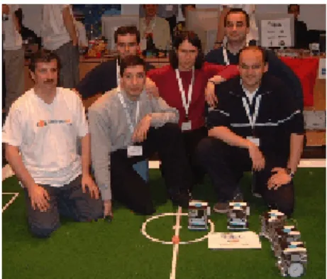
Fig. 5. Human team also showing robot's bar codes at German Open 2002 (old 5dpo robots on
the right side of the picture, with blue team colour)
Final Remarks
The 5dpo team kept last year omni-directional robots. They use an Electro-Magnetic passing/kicking device that allows controlling the force applied to the ball and sometimes is able to lift the ball over another robot. One drawback of this configuration is that is impossible to fit a active roller on the robot because the position where it should be placed is occupied by the kicker device. This obviously has important consequences on possible team strategies.
The vision system uses a single PC running Linux. It has two Firewire boards for the two cameras, one for each mid-field. This is needed to ensure that each camera can use the full bandwidth of the Firewire bus. The frames are hardware synchronised and the resolution is now 780x582 for each camera. The closed loop lag is under 50ms.
The bar code on top of the robots allows for good robot tracking and angle measurement and also prevents spurious blobs from being mistaken for a robot. This pattern has the advantage that it only uses the official colors for the robots and does not uses extra colors on top of the robots.