Acendino Alves da Silva Neto
Technological Evolution in Machining
Processes with CNC Machines in the
Context of the Concept of Industry 4.0
Master Thesis
Master in Industrial Engineering
Work done under the academic supervision of
Dr. Fernando Carlos Cabrita Romero
DECLARAÇÃO
Nome: Acendino Alves da Silva Neto
Endereço eletrónico:[email protected] Telefone:+351934658925 Número do Bilhete de Identidade: 18018131 9 ZZ9
Título da dissertação:
Technological Evolution in Machining Processes with CNC Machines in the Context of the Concept of Industry 4.0
Orientador(es):
Fernando Carlos Cabrita Romero Ano de conclusão: 2018
Designação do Mestrado:
Mestrado em Engenharia Industrial – Avaliação e Gestão de Projetos e Inovação
Nos exemplares das teses de doutoramento ou de mestrado ou de outros trabalhos entregues para prestação de provas públicas nas universidades ou outros estabelecimentos de ensino, e dos quais é obrigatoriamente enviado um exemplar para depósito legal na Biblioteca Nacional e, pelo menos outro para a biblioteca da universidade respetiva, deve constar uma das seguintes declarações:
1. É AUTORIZADA A REPRODUÇÃO INTEGRAL DESTA DISSERTAÇÃO APENAS PARA EFEITOS DE INVESTIGAÇÃO, MEDIANTE DECLARAÇÃO ESCRITA DO INTERESSADO, QUE A TAL SE COMPROMETE;
2. É AUTORIZADA A REPRODUÇÃO PARCIAL DESTA DISSERTAÇÃO (indicar, caso tal seja necessário, nº máximo de páginas, ilustrações, gráficos, etc.), APENAS PARA EFEITOS DE INVESTIGAÇÃO, MEDIANTE DECLARAÇÃO ESCRITA DO INTERESSADO, QUE A TAL SE COMPROMETE;
3. DE ACORDO COM A LEGISLAÇÃO EM VIGOR, NÃO É PERMITIDA A REPRODUÇÃO DE QUALQUER PARTE DESTA TESE/TRABALHO
Universidade do Minho, ___/___/______ Assinatura:
ACKNOWLEDGEMENTS
First of all, for this achievement and all the learning received during this course I would like to thank the architect of the universe, and the true essence of human beings, God.
I would like to thank the University of Minho and all the teachers from the School of Engineering for all the support and knowledge provided during the studies. In particular, I would like to thank my thesis advisor Dr. Fernando Carlos Cabrita Romero of the School of Engineering at the University of Minho. The door to Prof. Romero office was always open whenever I ran into a trouble spot or had a question about my research or writing. He consistently allowed this paper to be my own work, but steered me in the right direction whenever he thought I needed it.
I must express my very profound gratitude to my parents, Everaldo da Silva and Maria de Lourdes Santos da Silva for all the love and incentive during this work and for providing me with unfailing support and continuous encouragement throughout my years of study and through the process of researching and writing this thesis. This accomplishment would not have been possible without them.
I would like to thank my sister Karla Soraya Gomes dos Santos for all incentive and support in difficult times and would like to thank my sister Raeny Santos da Silva who helped me bring to the world a treasure of my life, my nephew, João Pedro Gomes da Silva.
I would also like to thank my family, friends and colleagues who shared moments, encouraged me and somehow helped to achieve this success.
ABSTRACT
The work related to the project of this dissertation will consist of an analysis of the technological evolution of the machining processes with CNC (Computer Numerical Control) machines regarding the new concept of Industry 4.0. The concept fits into the current transformation process for the fourth industrial revolution, such as integrated Cyber-Physical Systems (CPS) within the manufacturing processes using the Internet of Things (IoT) in industrial processes. Faced with technological advances, the processes of Industrial Engineering in machining using CNC machines must undergo adaptations, aiming at substantial increases in the operational effectiveness. Thus, an approach will be made to understand how current processes can adapt to the concept under study when analyzing the evolution of the machining tools for CNC machines in the face of new processes. A thorough study will be done to adapt the methodology of Industry 4.0 applying it to the machining processes in CNC Machines. Thereby, a proposal for future applications will be given on the topics studied. The methodology will be based entirely on a documental analysis research strategy.
The virtual technology in machining tools is still a subject in development, being one of the main factors to be understood in this dissertation. In this study, it will be possible to analyze the main factors that can influence directly or indirectly the production processes of a factory with CNC machines. It will be explored and studied the types of machining processes for CNC machines and the types of machining tools developed with virtual technology.
When we are talking about virtual technology, we are usually addressing the need for software. In CNC machining operations, there is a CAM (Computer Aided Manufacturing) software that performs machining simulations for CNC machines. Thus, a study and analysis of a production system involving a CAM software, a tool with virtual technology and CNC machines will be done to verify how this set can work encompassed and what changes this production model introduces. In the sequence of this study, an idea of a new production system will be proposed, allowing for a better understanding of the possibilities for application of new approaches in the future.
KEYWORDS
CNC Tools; CNC (Computer Numerical Control); CAM (Computer Aided Manufacturing); CPS (Cyber-Physical System); IoT (Internet of Things); Industry 4.0
RESUMO
O trabalho relacionado ao projeto desta dissertação de mestrado consistirá de uma análise da evolução tecnológica dos processos de usinagem com as máquinas CNC (Comando Numérico Computacional) em relação ao novo conceito da Indústria 4.0. O conceito se enquadra no atual processo de transformação da quarta revolução industrial, com os Sistemas Ciber-Físicos integrados (CPS) dentro dos processos de fabricação que utilizam a Internet das Coisas (IoT) em processos industriais. Diante dos avanços tecnológicos, os processos de Engenharia Industrial em usinagem utilizando máquinas CNC devem sofrer adaptações, visando um aumento substancial na eficácia operacional. Assim, uma abordagem será feita para entender como os processos atuais podem se adaptar ao conceito em estudo, visando também uma análise da evolução das ferramentas de usinagem para máquinas CNC em face de novos processos. Um estudo minucioso será feito para adaptar a metodologia da Indústria 4.0, aplicando-a aos processos de usinagem em máquinas CNC. Com isso, algumas proposta para aplicações futuras serão apresentadas para os tópicos estudados. A metodologia será totalmente baseada em uma estratégia de investigação documental.
A tecnologia virtual em ferramentas de usinagem ainda é um assunto em desenvolvimento, sendo um dos principais fatores a serem compreendidos na realização deste trabalho. Neste estudo, será possível analisar os principais fatores que podem influenciar direta ou indiretamente nos processos de produção de uma fábrica com máquinas CNC. Serão explorados e estudados os tipos de processos de usinagem para máquinas CNC e os tipos de ferramentas de usinagem desenvolvidas com tecnologia virtual. Quando abordamos o assunto sobre tecnologia virtual, geralmente estamos a lidar com a necessidade de um software. Nas operações de usinagem CNC, existe um software CAM (Manufatura Assistida por Computador) que realiza simulações de usinagem para máquinas CNC. Assim, um estudo e análise do sistema de produção envolvendo um software CAM, uma ferramenta com tecnologia virtual e máquinas CNC será feito para verificar como este conjunto pode trabalhar englobado e quais as mudanças para esse modelo de produção. Na sequência dessa análise, será proposta uma ideia de um novo sistema de produção, que permite uma melhor compreensão das possibilidades de aplicação no futuro das novas abordagens.
PALAVRAS-CHAVE
CNC (Controlo Numérico de Computadorizado); CAM (Manufatura Assistida por Computador); CPS (Sistema Cibernético Físico); IoT (Internet das Coisas); Indústria 4.0
TABLE OF CONTENTS
Acknowledgements ... iii
Abstract ... v
Resumo ... vii
List of Figures ... xiii
List of Tables ... xvii
Nomenclature and Abbreviation ... XVIII 1. Introduction ... 1
Framework and objective ... 1
Methodology ... 4
2. Literature Review: Industry 4.0 ... 7
The Concept of Industry 4.0 ... 7
Cyber-Physical System (CPS) ... 9
Smart Factories ... 11
Machine-to-Machine (M2M) ... 12
Internet of Things (IoT) ... 13
Internet Protocol version 6 (IPv6) ... 14
Machine Learning ... 15
3. Literature Review: CNC Machines ... 17
Concepts of CNC ... 17 Types of CNC Machines ... 18 3.2.1 Lathe Machine ... 18 3.2.2 Milling Machine ... 19 3.2.3 5 axis CNC Machine ... 19 CNC Programming ... 20 3.3.1 Requirements ... 20
3.3.2 CNC Programming by CAM (Computer Aided Manufacturing). ... 25
4. Literature Review: Machining tools for CNC machine ... 27
Process Machining for CNC ... 27
4.1.1 Turning ... 27
4.1.3 Drilling ... 28
CNC Tools ... 29
4.2.1 Requirements ... 29
4.2.2 CNC tools with cyber-physical technology ... 30
5. Exploring how the CNC tool developed with CPS works on the CNC ... 31
ISO 13399 – Cutting tool data representation and exchange ... 31
CNC Tool System ... 32
5.2.1 Cyber-Phisycal System (CPS) on CNC Tools ... 32
5.2.2 Internet of Things (IoT) on CNC Tools ... 35
Tool Functions ... 37
5.3.1 ToolPath code generators ... 37
5.3.2 In-cut monitoring ... 39
5.3.3 Process monitoring ... 40
Advantages in production ... 41
5.4.1 Virtual production control ... 42
5.4.2 Virtual interaction between human, machine and tool ... 42
5.4.3 Data saved on cloud ... 42
5.4.4 Reduction of inserts wastes ... 43
5.4.5 Collision detector ... 43
5.4.6 Machine Health inspector ... 43
Impact on Human Labor ... 44
5.5.1 The cutting parameters will not be only depend on human knowledge, if a similar process has been executed before. ... 45
5.5.2 Check the tool if the insert is damaged. ... 47
5.5.3 Decrease of tool preparation on CNC machines. ... 47
5.5.4 Decrease the verification of autonomous maintenance by the operator of the CNC machine 48 6. Proposal for future applications ... 49
Tool measurement ... 49
7. Studying how a CAM software works in communication between tools with Cyber
Physical System and a CNC machine ... 55
CAM communication ... 56
CAM functions ... 58
7.2.1 CAM Tool Library (Manufacturing set-up) ... 58
7.2.2 CAM cutting operations (Operations set-up) ... 60
Advantages of process simulation on CAM in communication with the tool with CPS 60 7.3.1 No need to draw the CNC tool on CAM process simulation. ... 61
7.3.2 No need to parameters calculation on CAM process simulation. ... 62
Impact on Human Labor ... 63
8. Proposal for future process applications ... 67
9. Study and analysis of the integrated production system with the tool with CPS, CNC machine and CAM software within the concept of Industry 4.0 ... 71
Architecture communication between CNC tool with Cyber-Physical Technology, CNC machine and CAM... 72
Technology combination within the concept of Industry 4.0 ... 73
Challenges in Industry 4.0 ... 76
9.3.1 The development of smart devices ... 76
9.3.2 The construction of the network environment ... 77
9.3.3 Big data analysis and processing ... 79
10. Final proposal for a new production model ... 81
Idea architecture ... 81
Idea development ... 84
Advantages in production ... 88
Impact on Human labor ... 89
Challenges on idea implementation ... 90
11. Conclusion and Outlook ... 93
Conclusion ... 93
Outlook ... 94
LIST OF FIGURES
Figure 1: Phases of Industrial Revolution. ... 8
Figure 2: Smart Factories on Industries 4.0. ... 9
Figure 3: CPS as a basis and enabler. ... 10
Figure 4: CPPS as a data processor. ... 11
Figure 5: Smart Factory in Industry 4.0. ... 12
Figure 6: Comparison between IPv4 and IPv6 ... 15
Figure 7: Machine learning algorithms ... 16
Figure 8: The movement of the axis of Lathe Machine. ... 18
Figure 9: The movement of the axis of Milling Machine. ... 19
Figure 10: The movement of the axis on 5 axis CNC Machine. ... 20
Figure 11: Workspace of EdgeCAM as a CAM software ... 25
Figure 12: Tuning operation on CNC Machine ... 27
Figure 13: Milling operation of CNC Machine ... 28
Figure 14: Drilling operation of CNC Machine ... 29
Figure 15: Simple parts of CNC Tool. ... 29
Figure 16: CoroPlus®, the tool with cyber-physical technology. ... 30
Figure 17: Cyber- Physical System on CNC communication. ... 33
Figure 18: Cyber- Physical System interaction on CNC machine, tool and operator in real time. ... 34
Figure 19: Flow data on process from CNC tool to CNC machine and Operator. ... 35
Figure 20: Internet of Things (IoT) versus Cyber- Physical System (CPS). ... 36
Figure 21: Architecture of CPS with IoT on CNC tool. ... 36
Figure 22: Directions of the traditional turning operations and the tool with ToolPath. ... 38
Figure 23: Comparison of the possibilities to use the inserts sides. ... 38
Figure 24: Internal system technology of the Silent Tool ... 39
Figure 25: Flow of data from turning process to the software. ... 40
Figure 26: System interaction between tool and machine if some problem occurs. ... 41
Figure 27: Process to do if some problem occurs with the traditional CNC tool. ... 46
Figure 28: Process if some problem occurs with the CNC tool with CPS. ... 46
Figure 29: Limit of the tool to execute the process. ... 48
Figure 31: Actual measurement process on CNC machines. ... 51
Figure 32: First proposal to measurement process on CNC machines. ... 52
Figure 33: Second proposal to measurement process on CNC machines. ... 53
Figure 34: Architecture of the process with interaction with social network. ... 54
Figure 35: Steps involved in the CNC program creation on CAM. ... 55
Figure 36: CAM workstation in DNC computer... 56
Figure 37: Architecture of the software interaction between the tools with CPS in communication with CAM. ... 57
Figure 38: EdgeCAM tool library as a CAM software ... 59
Figure 39: Sandvik ToolGuide workspace. ... 59
Figure 40: EdgeCAM cutting operations as a CAM software. ... 60
Figure 41: Tool design in Tool Library to import to CAM software. ... 62
Figure 42: Workspace of CAM software to fill the Speed and Feedrate calculation. ... 63
Figure 43: Flow information from Human to CAM. ... 64
Figure 44: Flow information from Human to CAM with tool software. ... 64
Figure 45: Three-dimensional space based on X, Y and Z axes. ... 67
Figure 46: Three-dimensional software collecting the point of measurement. ... 68
Figure 47: Finishing tool on lathe machine doing the measurement. ... 68
Figure 48: Interaction communication between CNC machine, CNC tool with CPS and CAM. ... 71
Figure 49: Flow information between CNC machine, CNC tool with CPS and CAM until the production of workpiece. ... 72
Figure 50: Different Challenges of Industry 4.0. ... 76
Figure 51: Proposal of architecture of flow information between CNC machine, CNC tool with CPS and CAM during the process production of workpiece. ... 82
Figure 52: The different architecture between the actual process using CNC tool with CPS and the proposal for the future process eliminating the waste time with machine stoppages ... 84
Figure 53: Information exchange between CNC tool with CPS and CNC machine during the measurement. ... 86
Figure 54: Automatic compensation of CNC machine software. ... 86
Figure 55: Implementation of a new operation on CAM (finishing with measurement). ... 87
Figure 56: Process interaction through social network. ... 88
Figure 57: Design Model ... 99
Figure 59: Manufacturing Model ... 100
Figure 60: Milling for manufacturing operation ... 100
Figure 61: Turning for manufacturing operation ... 101
Figure 62: Milling sequences for manufacturing operation ... 101
Figure 63: Turning sequences for manufacturing operation ... 102
Figure 64: NC post-processing, generate CNC code. ... 102
LIST OF TABLES
Table 1: G-codes ... 21 Table 2: M-codes ... 23 Table 3: Most used codes on CNC Programming ... 24
NOMENCLATURE AND ABBREVIATION
Nomenclature
𝑽𝑪 - Feedrate in meters per minute
𝑫 - Diameter of the cutter 𝒏 - Speed in rotation per minute
Abbreviation
API - Application Programming Interface BOM - Bill of Materials
CAD - Computer Aided Design
CAM - Computer Aided Manufacturing CNC - Computer Numerical Control
CPPS - Cyber-physical Production Systems CPS - Cyber-Physical Systems
CPU - Central Processing Unit CS - Cyber System
DNC - Direct Numerical control IC - Integrates Circuit
ICT - Information and Communication Technology IoS - Internet of Services
IoT - Internet of Things
IPv4 - Internet Protocol version four IPv6 - Internet Protocol version six
ISO - International Organization for Standardization M2M - Machine-to-Machine
MIT - Massachusetts Institute of Technology NC - Numerical Control
PCB - Printed Circuit Boards
PLC - Programmable Logic Controller PS - Physical System
RFID - Radio-Frequency Identification USA - United States of America
1.
INTRODUCTION
Framework and objective
The work related to the project of this dissertation will consist of an analysis of the technological evolution of the machining processes with CNC (Computer Numerical Command) machines regarding the new concept of Industry 4.0. The concept fits into the current transformation process for the fourth industrial revolution, such as integrated Cyber-Physical Systems (CPS) within the manufacturing processes using the Internet of Things (IoT) in industrial processes. This dissertation has the following specific objectives:
1) Adapt the methodology of Industry 4.0 applying it to the machining processes in CNC Machines.
2) Study of the issues related to the technological evolution of the tools used in CNC's with virtual technology.
3) Explore and study the types of machining processes for CNC machines and the types of machining tools developed with virtual technology.
4) Study and analysis the production system between a CAM software, a tool with virtual technology and CNC machine.
5) Develop proposals for future applications and enhancements on the studied topics. Currently, governments around the world are initiating programs to ensure competitiveness through adaptation to digital transformation (Kagermann, Wahlster & Helbig, 2013). In order to carry out this project, a detailed analysis of numerous primary, secondary and tertiary literary sources will be carried out in relation to the proposed topic related to Industry 4.0 and the principles it approaches, correlating it with the machining processes in CNC machines and with operation tools with virtual technology, which are currently under development. As such, scientific articles, books, and dissertations addressing the topic related to the purpose of this work will be researched and analyzed. Subsequently, with the conclusion of the archival research, all the relevant information will be synthesized in a critical review of the literature - so that it is possible to develop a complete and detailed knowledge and understanding regarding the proposed theme.
Simultaneously and in parallel, in order to reach the first objective of this dissertation, a thorough study will be done to adapt the methodology of Industry 4.0 applying it to the machining processes in CNC Machines. For this study, it will be necessary a research and an
analysis of scientific articles, books, and dissertations, which contain research related to the Industry 4.0 and subjects related to the technological evolution of the tools used in CNC Machines with virtual technology, aiming at the improvement of the machining processes. With the knowledge acquired, a framework will be established between the methodology of Industry 4.0 and the machining processes, in order to present a better opportunity of execution in the machining processes for CNC machines. For the development of this first objective it will be crucial the knowledge of the methodology of Industry 4.0 and the processes of machining with CNC Machines.
In the next phase, we know that one of the main factors that influence the development of machining processes in CNC machines are the tools used in CNC machining processes for the production of pieces or similar artifacts. Therefore, for the development of the second objective, a deep study of the issues related to the technological evolution of the tools used in CNC's with virtual technology will be necessary. The virtual technology in machining tools is still a subject in development, being one of the main factors to be understood in this work. In this study, it will be possible to analyze the main factors that can influence directly or indirectly the production processes of a factory with CNC machines. After all, the communication system between the tool and the machine will be totally virtual, having greater precision regarding the wear and friction information about the tool, working more efficiently with a system included between CNC machine, tool, and software - where human intervention to check whether the quality of the tool is good or not will not be necessary or it will be greatly reduced. Thereby, a study of the impact of human labor will be done.
Considering that the requisite "CNC machining tools" is one of the main factors that can affect, beneficially or not, the execution of machining processes in the CNC's, and in order to carry out the third objective presented in the objectives of this dissertation, it will be explored and studied the types of machining processes for CNC machines and the types of machining tools developed with virtual technology. In this part of the dissertation an analysis of how the machining operations (drilling, milling, turning, etc.) may undergo modifications in the execution will be made, emphasizing tools with virtual technology.
When we are talking about virtual technology, we are usually addressing the need for software. In CNC machining operations, there is a CAM (Computer Assisted Manufacturing) software that performs machining simulations for CNC Machines in a not very efficient way, because there is an immense need for the programmer's knowledge, in view of the type of CNC Machine, tools, what kind of workpiece material and production data (cutting speed, RPM, cutting feed, etc.) - where all this information is transmitted to the software by the programmer.
If there is any incorrect information or if it is not according to the type of material, or if there is non-ideal machining data, there will be a direct impact on the execution of the machining process. Therefore, the fourth objective of this dissertation will study and analyze the production system between a CAM software, a tool with virtual technology and CNC machine to verify how this set can work encompassed and what changes to this new production model. In order to analyze how this encompassed communication can work more efficiently without the immense need of the programmer's knowledge. That objective will be integrated on the concept of Industry 4.0 to achieve the main objective as mentioned above. Thereby, during the development of this work, it come up an idea of a new production model, and this idea will be proposed, which involves an architecture, development, identification of advantages in production, considerations on the impact in human labor and it will present the challenges of implementation for better understanding the possibilities for application in the future. So, as the last objective of this dissertation, some proposals for future applications concerning the suited topics will be suggested.
In chapters 2, 3 and 4 a literature review of the main concepts will be made to acquire a better understanding for the development of the objectives in this dissertation. Chapter 5 addresses the adaptation of the methodology of Industry 4.0 applying it to the machining processes in CNC Machines. In Chapter 6, a proposal will be suggested to have a better process production for future applications in machining processes in CNC machines succeeding the methodology of Industry 4.0. Chapter 7 aims to study how a CAM software works in communication between the tool with CPS and a CNC machine, presenting the CAM possibilities of connection and effects. Chapter 8 proposes an idea of how a new method of measurement could be done by the CNC tool with CPS during the process execution. Chapter 9 will explore and analyse how the production system works encompassing the tool with CPS, the CNC machine, a CAM software, and the concept of Industry 4.0. Finally, Chapter 10 presents a general proposal for a new production model and a better production system for machining areas. This final proposal will show how this new production model could work integrating the tool with CPS, CNC machines and CAM software in a better way than existing models, and will show the new idea of communication interaction between them.
Methodology
The methodology used during the development of this dissertation was based entirely on a documental research strategy. The bibliographic research was based in scientific publications on the machining area, machining processes, CNC machines, CAM and CAD software and the context of Industry 4.0. A new tool with cyber-physical technology has emerged in the CNC machining area, a technology with a combination of sensors, algorithms, the cloud, data analysis, and connectivity with Internet of Things (IoT), has provided the focus for this study, in order to highlight what changes could be done on actual processes on CNC machines. The methodology of this dissertation also has been based on the author´s experience of programming and operation of CNC´s machines during his eight years of experience with machining processes engineering. Through it, the topics addressed in this dissertation were compared to the problems experienced by the author to suggest what the changes could be done to future applications in the context of Industry 4.0. In this sense, data collection methods for this research involves also observation, and primary data, besides the collection of secondary data from documental sources. So, a detailed analysis of numerous literary sources has been carried out in relation to the proposed topic related to the context of Industry 4.0 and the principles it approaches, correlating it with the machining processes in CNC machines and with operation tools with virtual technology, which are currently under development. All the relevant information was synthesized in a critical review of the literature.
The study done to adapt the methodology of Industry 4.0 applying it to the machining processes in CNC machines was based on scientific articles, books, and dissertations, which contained research related to the Industry 4.0 concept and subjects related to the technological evolution of the tools used in CNC Machines with virtual technology.
The study of the issues related to the technological evolution of the tools used in CNC's with virtual technology has been made through scientific publications and the information given by the company´s developer, Sandvik, through the catalogue and site. The virtual technology in machining tools is still a subject in development, being one of the main factors to be understood in this work.
Research on the types of machining processes for CNC machines and the types of machining tools developed with virtual technology has been made through scientific publications and books about machining processes and CNC machines, having in mind how the machining operations may undergo modifications, emphasizing tools with virtual technology.
The research on the production system integrating a CAM software, a tool with virtual technology and CNC machines, was made to verify how this set can work together and what changes it implies. The research has been made through scientific publications and books. The proposals suggested by the author on the following chapters, concerning improvements in CNC machines, software and production model, were developed based on the author´s knowledge acquired during his experience, and on the documental research made during the development of this dissertation.
2.
LITERATURE REVIEW: INDUSTRY 4.0
This chapter presents the main concepts studied and analyzed about the Industry 4.0 paradigm to carry out the necessary research for this master thesis.
The Concept of Industry 4.0
The concept fits into the current transformation process for the fourth industrial revolution, such as integrated Cyber-Physical Systems (CPS) within the manufacturing and logistics processes using the Internet of Things (IoT) and the Internet of Services (IoS) in industrial processes (Platform Industry 4.0, 2017). The definition of the term Industry 4.0 was first presented in 2011 by the famous Hannover Fair as a project in the High-Tech Strategy of German Industry (Hermann, Pentek & Otto, 2015). Shortly thereafter, in the year 2013, the German working group presented a report about Industry 4.0 (Hermann et al., 2015). The report defined the environment for Industry 4.0, which included a strong customization of the products obtained with high flexibility of mass production (better technology in automation), presenting an introduction of the methods of systems with own organization (own automation, own configuration, own diagnosis, etc.) to obtain an adequate connection between the real world (people and machine) and the virtual world (Devezas, Leitão & Sarygulov, 2017). This new era of industry is centered on the intensive use of advanced Information and Communication Technology (ICT) resources in order to ensure greater flexibility in production systems and processes, as a consequence the increasing complexity of products and supply chains (Faller & Feldmüller, 2015).
The industrial revolutions are characterized by radical changes, motivated by the incorporation of technologies, which is reflected in the economic, social and political field. Until nowadays the consensus was that there were three industrial revolutions. The first occurred between the years of 1760 and 1840, dominated by technologies such as steam and hydraulic machines, and has as a symbol of this phase there was the advent of the first automated machining loom and other textile machinery. The second revolution took place between the late nineteenth and early twentieth centuries, represented by the introduction of electricity, the assembly line and the emergence of production based on a high, accentuated division of labor. The third stage of industrialization began around the 1960s, and is marked by the development of semiconductors, and technologies such as mainframes and personal computers. It was the age of the emergence and diffusion of electronics and information and communication technologies (ICTs), which
later in the 1990s saw the emergence of the Internet (FDC, 2016). Figure 1 briefly shows the succession of revolutions and characterizes each one.
Source: (Kagermann et al., 2013)
Figure 1: Phases of Industrial Revolution.
This new paradigm of the industry has as main purpose which is the consolidation of intelligent factories. It highlights the dissemination of Cyber-Physical Systems (CPSs), the evolution of embedded systems, allowing the implementation of the Internet of Things (IoT) and Services (IoS), making each input, feature or product a network-connected and mappable object. Cyber-Physical Systems correspond to the evolution of embedded systems in the form of devices distributed and connected to wireless networks with the ability to communicate with each other and with the Internet. That results in the convergence between the physical and virtual world (cyberspace). Accompanying this movement is the enhancement of network protocols such as IPv6, which provides enough network addresses to allow connectivity with intelligent objects via the Internet. This fact enables the conditions for the creation of the Internet in which resources, information, objects and persons will be connected in specific and particular ways. This technological evolution affects industry, and in the scope of manufacturing is described as the fourth stage of industrialization, or Industry 4.0 (Kagermann et al., 2013).
The main purpose of Industry 4.0, enabled by the convergence and integration of emergent and new technologies, is the creation of smart factories. These are capable of managing process complexity, operate with less disruption, and more efficiently. The interaction between humans, machines and resources resembling a social network (Kagermann et al., 2013) as you can see in Figure 2. In these installations, cyber-physical systems monitor physical plant processes and make decentralized decisions. Physical systems are converted into objects of the Internet of things, communicating and collaborating with each other and with humans in real time through wired and wireless networks connected to the Web (Marr, 2016).
Source: (Gigamon, 2017)
Figure 2: Smart Factories on Industries 4.0.
Cyber-Physical System (CPS)
In the general conception of CPS, it is a system formed by collaborative virtual entities intensely connected to the physical world and their processes in progress and interaction, consuming and providing access to data and data processing services available on the Internet (Acatech, 2011). According to the Report of the Steering Committee for Foundations and Innovation for Cyber-Physical (NIST, 2013), CPS´s have a great potential for modifying various aspects of life, allowing the development of concepts such as autonomous cars, robotic surgery, intelligent buildings, intelligent electrical network, intelligent manufacturing and implanted medical devices.
Specifically, in the scope of manufacture, Cyber-Physical Systems (CPS) correspond to the physical and virtual systems in an integrated network that brings together physical resources and processes (Gorecky, 2014). In these networks multiple information from different sources circulates that is monitored and synchronized between the factory and cyberspace (Lee, Bagheri
& Kao, 2015). The intelligent CPS, machinery and installations are able to exchange information autonomously, perform drives and control to others independently (Kagermann et al., 2013). According to Macdougall (2014), cyber-physical systems create the conditions for Internet of Things (IoT) which are combined with Internet Services (IoS) for Industry 4.0. The interaction between systems based on high-performance software and dedicated user interfaces, integrated with digital networks, creating a new universe of functionalities for systems, making CPS simultaneously a basis and enabler, as represented in Figure 3. Thereby, the CPS´s represent a paradigm shift from business models and the development of new applications, services and value chain.
Source: (I-Scoop, 2016)
Figure 3: CPS as a basis and enabler.
One of the concepts of Cyber-physical Systems is the Cyber-physical Production Systems (CPPS). These consists of machines, warehouses, logistics and intelligent production facilities that have been digitally mapped and enable the end-to-end integration of ICTs, from inbound logistics to outbound logistics and services, through production and marketing (Kagermann et al., 2013). It also has the function of enabling communication between machine, human and products as the example in Figure 4 shows. Elements of a CPPS will be able to acquire and
process data, to self-control certain tasks and interact with humans through interfaces (Monostori, 2015).
Source: (Ecosystems 4 innovators, 2016)
Figure 4: CPPS as a data processor.
Smart Factories
The main objective of Industrial 4.0 is to consolidate the "Intelligent Factories" concept to allow the customized on demand products and services according to the necessity of consumers (Pisching et al. 2015). As Deloitte (2017) argues, the smart factory is a flexible system that can self-optimize performance across a broader network, self-adapt to and learn from new conditions in real or near-real time, and autonomously run entire production processes.
The fusion of physical and virtual worlds through cyber-physical systems and the concomitant fusion of business processes and technical processes are opening the way for a new industrial era synthesized by the concept of "Smart Factory", which falls within the scope of the Industry 4.0 strategy.
The implementation of Cyber-physical systems in systems of production makes the concept of "intelligent factories" emerge. High levels of automation are applied in intelligent factories. This is possible because of flexible networks of production systems based on cyber-physical systems, supervising processes automatically. Flexible production systems, which are capable
of responding in almost real time, allow the internal production processes to be radically optimized. The production advantages are not limited or constrained to exclusively one production unit. They can also be optimized according to a global network of adaptable and self-organizing production units belonging to more than one operator Figure 5 (Macdougall, 2014).
Source: (Kagermann et al., 2013)
Figure 5: Smart Factory in Industry 4.0.
Machine-to-Machine (M2M)
The two major elements that enable to change the manufacturing environment to what is called Industry 4.0 is Machine-to-Machine (M2M) communication in combination with the Internet of Things (IoT). The concept of Machine-to-Machine (M2M) refers to communication between the machines with computerized capacity and communication without necessity of human intervention (Kim, 2014).
The data created by these machines could be saved and used by an application of useful data. The M2M communications are used for automated data transmission and measurement between mechanical or electronic devices. Typical components of an M2M system are: field deployed, wireless devices with embedded sensors or RFID and Wireless communication networks (Advantech, 2015).
A M2M service forms a Cyber-Physical system (CPS) where data is coming from sensors of physical machines and is analyzed, then converted to a value in a cloud computing environment (a cyber space). The data consequently becomes part of “Big Data” and data analytics and optimization can be performed, being now one of the main issues in information technology and service science communities. Recently, M2M service has attracted increasing attention from business and innovation perspectives in scientific and technological communities. A remote maintenance system using M2M communication is a typical and commercially successful application (Uchihira, Ishimatsu, Sakura, Kageyama, Kakutani, Mizushima & Yoneda, 2015).
Internet of Things (IoT)
The Internet of Things (IoT), is considered as an emergent technological wave in the global information industry. According to Chen, (2014), IoT is a network that connects all things to the Internet for the purpose of exchanging information and locating devices through pre-established protocols. IoT achieves the goal of promoting an intelligent identification, tracking and managing things. It is the extension and the concept of an Internet based on networks, which expands the paradigm of people to people, and things, or between things and things.
There is no final and absolute definition for IoT, since experts in the field have different perspectives on the subject. However, following expected technological evolution, it is possible to identify some characteristics that IoT should have (Chen, 2014):
• Comprehensive Perception - Using RFID, sensor, and barcode resources for information anywhere, anytime. From this perspective, communication systems and information will be incorporated imperceptibly and naturally in the environment. The networks will allow people to interact remotely with the real world.
• Reliable Transmission - A set of technologies for radio networks, telecommunication networks and the internet will allow the transmission and availability of information between network objects at any time. IoT creates the interaction between the physical world, the virtual world, the digital world and society.
• Intelligent Processing - will support IoT applications by collecting data for databases, various intelligent computing technologies, including cloud computing. Network service providers can process a large volume of messages instantly through cloud computing. Thus, this technology will be the promoter of IoT.
Internet Protocol version 6 (IPv6)
The Internet Protocol (IP) is the most widely used communications protocol because it is the most pervasive communication technology. The protocol known as Internet Protocol version 4 (IPv4) has been the protocol used for the initial stage of the Internet, and currently is almost extinct, due to the demand for use (Wu, 2013). Initially, IPv4 was designed to support just over 4 billion IP addresses, due to its 32-bit limitation, that were created to support the necessity. However, with the advent of IoT solutions, the necessity for addresses has increased, and according to the Ericsson company forecast in 2011, the number of connected things could reach 50 billion by 2020 (Nordrum, 2016). It is clear that the current capacity of IPv4 will not support this new demand, so companies should plan to migrate to the IPv6 protocol.
On this line, IPv6 addresses this gap, since it supports up to 340 deconstructions of addresses. It is composed of two parts (64 bits for network prefix and 64 bits for interface identifier), which will meet the need for IoT solutions in its fullness. In addition, IPv6 has better mobility and security compared to IPv4, since it is considered a mature and viable solution for the next generation of the Internet (Wu, 2013). Figure 6 shows the difference between the IPv4 and IPv6 header.
Source: (Wu, 2013).
Figure 6: Comparison between IPv4 and IPv6
Machine Learning
The first definition of machine learning was cited by Samuel (1959), defining it as the field of study that gives computers the ability to learn without being explicitly programmed. It was later redefined by Mitchell (1997), as techniques capable of improving his performance in a given task using previous experiences. According to Mitchell (1997), the algorithms for machine learning can be divided into four forms: supervised, unsupervised, semi supervised and reinforcement learning.
In supervised learning, data (inputs and outputs) are presented by means of a model, providing for each input the desired output, where the main objective is to learn a general rule in order to understand inputs and outputs. In unsupervised learning, no information is given to the algorithm, letting the algorithm itself understand the structure of the data. In the semi
supervision algorithm, a training set is provided with some missing outputs. Reinforcement learning is about the interaction with a dynamic environment in which a specific goal is proposed, taking as a classic example the autonomous vehicles. The learning algorithms can be divided into predictive (classification and regression) and descriptive (grouping, summarization and association). The algorithms are used according to the purpose and the problem to be solved. This mind map, still not exhaustive, made by Jason Brownlee at Machine Learning Mastery highlights a number of diverse classes and subclasses of algorithms and approachs applied in Machine Learning, as Figure 7 shows.
Source: (Data Science Central, 2016)
3.
LITERATURE REVIEW: CNC MACHINES
This chapter presents the main concepts studied and analyzed about the types of programming of CNC Machines to carry out the necessary research for the project.
Concepts of CNC
Computer Numerical Control (CNC) is a control system that accepts a set of programmed instructions to control machines, mainly used in Lathe and Milling machines in machining processes. The system allows the simultaneous control of several axes, through a list of movements written in a specific code (G-codes). The CNC is an evolution from Numerical Control (NC), this technology was developed by the servomechanisms laboratory of MIT (Massachusetts Institute of Technology) in the USA. The development of NC technology can be categorized into various generations as listed below (Radhakrishnan, 2008):
• First generation: The NC machines were built associating devices and vacuum tubes that consumed a lot of power and the storage capacity was poor.
• Second generation: The machines were created with transistors to use the PCB (Printed Circuit Boards). However, the size of the PCB was large and not satisfactory.
• Third generation: During the mid-60s, the concept of Integrated Circuit (IC) revolutionized the electronics world further. Thyristor Controlled DC drive became popular during this period. From the totally hardwired design, the design of NC machine become soft wired. At the same time, another development was the concept of evolution of direct numerical control technique by which several NC machines could be controlled by the a single host computer.
• Fourth generation: Near the end of 1970, microprocessors came to be used as a CPU of the computers, impacting on the design of CNC machine tools. Initially 8 or 16bit microprocessors were used. The system was improved and nowadays many CNC systems are based on 32 and 64 bit microprocessors as well.
Types of CNC Machines
When the CNC was created, the technology was adopted to fit on existing machines. Nowadays, the CNC technology is still being retrofitted to various machine tools, but there are many machines that were created for the specific purpose of being CNC machines (CNC 4 Everyone, 2018). For the sake of the study of the types of CNC machines for this dissertation, three main types of machining processes will be analyzed, which are: Lathe Machine, Milling Machine and 5 axis CNC Machine.
3.2.1 Lathe Machine
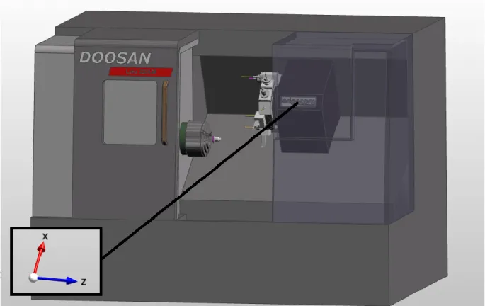
Normally, these machines are composed by two axis to program (X and Z) through G-codes, one Tool Turret and one Spindle. These machines rapidly rotate the material on a spindle. During the rotation of the spindle, the material is pressed against the tools to remove the materials and give shape as programmed. Lathes are mostly used to cut symmetrical objects such as spheres, cones and cylinders (Tag Team Manufacturing, 2017). Figure 8 shows a Lathe Machine and the movement of the axis.
Source: Figure retrieved from EdgeCAM software and modified by the author.
3.2.2 Milling Machine
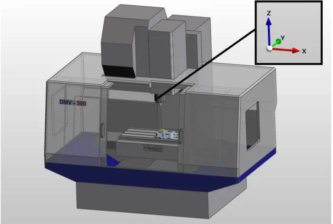
The Milling machines usually are composed by three axis to program (X, Y and Z) through G-codes and one Table fix the material and sometimes, composed by one spindle to give the rotation when desired. Some of these machines are absolutely massive, have built in tool changers, auto-feed mechanisms for loading in material and various electrical sensors for safe monitored machining (CNC 4 Everyone, 2018). Figure 9 shows a Milling Machine and the movement of the axis.
Source: Figure retrieved from EdgeCAM software and modified by the author.
Figure 9: The movement of the axis of Milling Machine.
3.2.3 5 axis CNC Machine
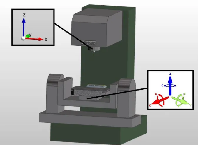
The 5 axis Machines as the name suggest is composed by five axis to program (X, Y and Z, as normal axis and A, B or C as rotary axis) through G-code programming. Normally, the axis X, Y and Z act on similar behavior of Milling Machine, the difference between them is because the 5 axis Machine has two more rotary axes. The rotary axes allow much more complex machining to produce parts that would be impractical to do on a normal CNC milling (CNC 4 Everyone, 2018). Figure 10 shows a 5 axis CNC Machine and the movement of the axes.
Source: Figure retrieved from EdgeCAM software and modified by the author.
Figure 10: The movement of the axis on 5 axis CNC Machine.
CNC Programming
3.3.1 Requirements
Firstly, as Smid (2005) suggested to program a CNC machine, the programmer should always do before writing the program, is to evaluate the drawing in order to get a general idea about the part. Such an evaluation includes several observations that can be summed up:
• Drawing units and scale • Dimensioning method • Tolerances
• Material type, size, shape and condition • Surface finish requirements
• Drawing revisions
• Bill of Materials (BOM) - if available • Omissions and other errors
The CNC programming normally is based on G-codes. The G-codes is the language in which people tell computerized machine tools how to make something. These programs by G-code instructions are provided with a machine controller (industrial computer) that tells the motors where to move, how fast to move, and what path to follow (CMI, 2018). The CNC programming could be done manually by the CNC programmer or by CAM (Computer Aided Manufacturing). The most used G-codes are shown in Table 1 followed by the M-codes on
Table 2 as used to program CNC machines in complement with G-codes.
Table 1: G-codes
Source:(CNC Cookbook, 2018).
Code Category Function Notes
G00 Motion Move in a straight line at rapids speed. XYZ of endpoint
G01 Motion Move in a straight line at last speed
commanded by a (F)eedrate
XYZ of endpoint
G02
Motion Clockwise circular arc at (F)eedrate XYZ of endpoint IJK relative to center R for radius
G03
Motion Counter-clockwise circular arc at (F)eedrate XYZ of endpoint IJK relative to center R for radius
G04 Motion Dwell: Stop for a specified time. P for milliseconds X
for seconds
G05 Motion FADAL Non-Modal Rapids
G09 Motion Exact stop check
G10 Compensation Programmable parameter input
G15 Coordinate Turn Polar Coordinates OFF, return to
Cartesian Coordinates
G16 Coordinate Turn Polar Coordinates ON
G17 Coordinate Select X-Y plane
G18 Coordinate Select X-Z plane
G19 Coordinate Select Y-Z plane
G20 Coordinate Program coordinates are inches
G21 Coordinate Program coordinates are mm
G27 Motion Reference point return check
G28 Motion Return to home position
G30 Motion Return to the 2nd, 3rd, and 4th reference point
G32 Canned Constant lead threading (like G01
synchronized with spindle)
G40 Compensation Tool cutter compensation off (radius comp.)
G41 Compensation Tool cutter compensation left (radius comp.)
G42 Compensation Tool cutter compensation right (radius comp.) G43 Compensation Apply tool length compensation (plus)
G44 Compensation Apply tool length compensation (minus)
G49 Compensation Tool length compensation cancel
G50 Compensation Reset all scale factors to 1.0
G51 Compensation Turn on scale factors
G52 Coordinate Local workshift for all coordinate systems: add
XYZ offsets
G53 Coordinate Machine coordinate system (cancel work
offsets)
G54 Coordinate Work coordinate system (1st Workpiece)
G55 Coordinate Work coordinate system (2nd Workpiece)
G56 Coordinate Work coordinate system (3rd Workpiece)
G57 Coordinate Work coordinate system (4th Workpiece)
G58 Coordinate Work coordinate system (5th Workpiece)
G59 Coordinate Work coordinate system (6th Workpiece)
G61 Other Exact stop check mode
G62 Other Automatic corner override
G63 Other Tapping mode
G64 Other Best speed path
G65 Other Custom macro simple call
G68 Coordinate Coordinate System Rotation
G69 Coordinate Cancel Coordinate System Rotation
G73 Canned High speed drilling cycle (small retract)
G74 Canned Left hand tapping cycle
G76 Canned Fine boring cyle
G80 Canned Cancel canned cycle
G81 Canned Simple drilling cycle
G82 Canned Drilling cycle with dwell (counterboring)
G83 Canned Peck drilling cycle (full retract)
G84 Canned Tapping cycle
G85 Canned Boring canned cycle, no dwell, feed out
G86 Canned Boring canned cycle, spindle stop, rapid out
G87 Canned Back boring canned cycle
G88 Canned Boring canned cycle, spindle stop, manual out
G89 Canned Boring canned cycle, dwell, feed out
G90 Coordinate Absolute programming of XYZ (type B and C
systems)
G90.1 Coordinate Absolute programming IJK (type B and C
systems)
G91 Coordinate Incremental programming of XYZ (type B and
C systems)
G91.1 Coordinate Incremental programming IJK (type B and C
systems)
G92 Coordinate Offset coordinate system and save parameters
G92.1 Coordinate Cancel offset and zero parameters
G92.2 Coordinate Cancel offset and retain parameters
G92.3 Coordinate Offset coordinate system with saved
parameters
G94 Motion Units per minute feed mode. Units in inches or
mm.
G95 Motion Units per revolution feed mode. Units in
inches or mm.
G96 Motion Constant surface speed
G97 Motion Cancel constant surface speed
G98 Canned Return to initial Z plane after canned cycle
G99 Canned Return to initial R plane after canned cycle
Table 2: M-codes
Source:(CNC Cookbook, 2018).
Code Category Functions Notes
M00 M-Code Program Stop (non-optional)
M01 M-Code Optional Stop: Operator Selected to Enable
M02 M-Code End of Program
M03 M-Code Spindle ON (CW Rotation)
M04 M-Code Spindle ON (CCW Rotation)
M05 M-Code Spindle Stop
M06 M-Code Tool Change
M07 M-Code Mist Coolant ON
M08 M-Code Flood Coolant ON
M09 M-Code Coolant OFF
M17 M-Code FADAL subroutine return
M29 M-Code Rigid Tapping Mode on Fanuc Controls
M30 M-Code End of Program, Rewind and Reset Modes
M97 M-Code Haas-Style Subprogram Call
M98 M-Code Subprogram Call
M99 M-Code Return from Subprogram
The CNC programming is not just based on G-codes or M-codes, there are other functions that are used to program as well. The most frequently codes to program a CNC machine is shown in Table 3 (Smid, 2005).
Table 3: Most used codes on CNC Programming
Source:(Smid, 2005).
Code Description
A Absolute or incremental position of A axis (rotational axis around X axis)
B Absolute or incremental position of B axis (rotational axis around Y axis)
C Absolute or incremental position of C axis (rotational axis around Z axis)
D Defines diameter or radial offset used for cutter compensation. D is used for depth
of cut on lathes. It is used for aperture selection and commands on photoplotters.
E Precision feedrate for threading on lathes
F Defines feed rate
G Address for preparatory commands
H Defines tool length offset.
I Defines arc center in X axis for G02 or G03 arc commands.
Also used as a parameter within some fixed cycles.
J Defines arc center in Y axis for G02 or G03 arc commands.
Also used as a parameter within some fixed cycles.
K Defines arc center in Z axis for G02 or G03 arc commands.
Also used as a parameter within some fixed cycles, equal to L address.
L Fixed cycle loop count;
Specification of what register to edit using G10
M Miscellaneous function
N Line (block) number in program;
System parameter number to change using G10
O Program name
P Serves as parameter address for various G and M codes
Q Peck increment in canned cycles
R Defines size of arc radius, or defines retract height in milling canned cycles
S Defines speed, either spindle speed or surface speed depending on mode
T Tool selection
U Incremental axis corresponding to X axis (typically only lathe group A controls)
V Incremental axis corresponding to Y axis
W Incremental axis corresponding to Z axis (typically only lathe group A controls)
X Absolute or incremental position of X axis.
Also defines dwell time on some machines (instead of "P" or "U").
Y Absolute or incremental position of Y axis
3.3.2 CNC Programming by CAM (Computer Aided Manufacturing).
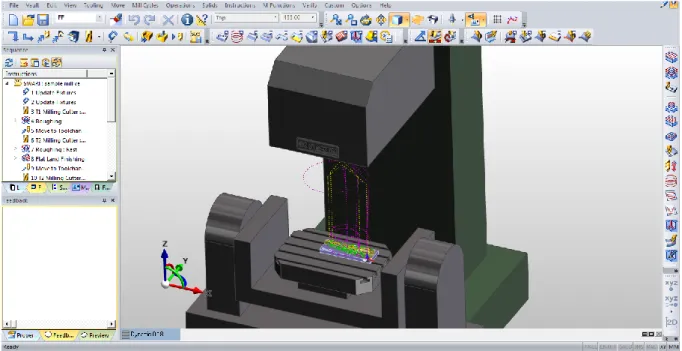
Using the codes suggested on tables before, it is possible to create manually a program for some desired work-piece using the right CNC Machine. Instead of it, for more complicated workpieces, there is another possibility to create a CNC program, which is by using a CAM software. The CAM systems work on the basis of mathematical models from the CAD (Computer Aided Design) system. Through these models the systems generate a toolpath file through the postprocessor (software that generates the machine-specific command program) on CAM. Through the CAM systems it is possible to transfer all coordinates, so the CNC Machines carry out the machining of the part (John, 1984).
The CAM software permits a simulation on a computer before a real execution on CNC Machine, but the program parameters are totally dependent from the CNC programmer. Figure
11 shows the workspace of EdgeCAM as a CAM software and then an example of the program
generated by the postprocessor.
Source: Figure retrieved from EdgeCAM software.
Figure 11: Workspace of EdgeCAM as a CAM software
An example of the CNC program generated by EdgeCAM´s postprocessor for Lathe Machine:
%_N_CEN0000_MPF ;$PATH=/_N_MPF_DIR
N10 G0 G54 X200 Z200 T0 M5 N20 T301 ;(EXT./PCLNL-2525-M12/R.4) N30 G96 S150 M3 N40 G92 S1200 N50 G0 X-3.864 Z0.946 M8 N60 G1 X-0.4 Z-0.054 F0.2 N70 X14.32 Z-4.303 N80 G3 X14.712 Z-4.594 I-0.2 K-0.346 N90 G1 X25.372 Z-42.517 N100 X28.468 Z-45.198 F.2 N110 G3 X28.574 Z-45.398 I-0.346 K-0.2 N120 G1 Z-48.676 N130 X30.838 Z-47.545 N140 G0 Z10 N150 G0 G54 X200 Z200 T0 M9 N160 M30 %
4.
LITERATURE REVIEW: MACHINING TOOLS FOR CNC MACHINE
Process Machining for CNC
The operations on process machining for CNC are chosen by analyzing of the technical drawings to execute the workpiece (Vedric, 2013). From the sample drawing, even a casual look will identify the types of operations required to machine the part (Smid, 2005). Actually, there are numerous operation of CNC machine, but basically the most used are three:
• Turning • Milling • Drilling
4.1.1 Turning
Normally turning operation is executed on Lathe Machines, where the Spindle fixes the material through the Chuck, rotating against the tool and transforming on the workpiece as desired. Turning is a process that generates cylindrical and rounded forms with a single point tool. The workpiece rotates against the tool. On metal cutting, Turning is the most common process, is a highly optimized process. Thereby, it requires various factors in the turning application. Turning can split in numerous simple applications on CNC machines (longitudinal turning, facing or profiling) for selection of tool types, cutting data and programming (Sandvik Coromant, 2017). Figure 12 shows an example of a turning operation.
Source: (Sandvik Coromant, 2017)
4.1.2 Milling
The Milling operation different from the Turning operation. The tool rotates against the workpiece removing material to transform the shape as desired. Milling is the machining process of using rotary cutters to remove material (Sandvik Coromant, 2017). This process is one of the most used on CNC machines, because it covers a wide variety of different operations and machines. Figure 13 shows an example of milling operation.
Source: (Sandvik Coromant, 2017)
Figure 13: Milling operation of CNC Machine
4.1.3 Drilling
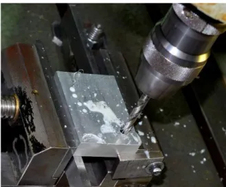
Drilling as the name suggest is a cutting process that uses a drill to cut a hole of circular cross-section in solid materials. Drilling is another common process of CNC machines. In Lathe Machines the workpiece rotates against the drill. Concerning to Milling machines and 5 axis CNC machines, the drill is pressed against the workpiece and rotated removing the material (Sandvik Coromant, 2017). Figure 14 shows an example of Drilling operation.
Source: (Doc Player, 2018)
Figure 14: Drilling operation of CNC Machine
CNC Tools
4.2.1 Requirements
The tools used on CNC Machines are chosen in accord with the processes to be executed. For each process operation there are many types of tools, but basically they are built on the same principle, remove the material through the forces applied from the workpiece or tool to transform the raw material into a shape desired as a final workpiece (Sandvik Coromant, 2017). The machining tools are usually composed of a tool body and a cutting edge for removal of material as shown in Figure 15. The cutting edge is usually made through the inserts to remove exchanges when damaged.
Source: Figure retrieved from Sandvik Coromant and modified by the author.
4.2.2 CNC tools with cyber-physical technology
Actually, the tools with cyber-physical technology is a term totally new on machining. As the manufacturing on automotive industry has employed connectivity, remote monitoring and intelligent use of data for years, the company Sandvik, one of the most important companies on development of CNC tools cutting edge, recently introduced a new tool with cyber-physical technology, the CoroPlus®. According to Sandvik Coromant (2017) this new tool is a combination of sensors, connectivity, algorithms, the cloud, data analysis and connection with Internet of Things (IoT) that can help improves the manufacturing process, cut costs and reduce waste. The ever-increasing digitalization of manufacturing opens new opportunities to increase the productivity and effectiveness (Botkina, Hedlind, Olsson, Henser, & Lundholm, 2018). For this new technology on tools, the International Organization for Standardization (ISO), developed the ISO 13399. For Botkina et al., (2018), the ISO 13399 is today the international technical standard for information to exchange information between various software servicing cutting tools and holders, and between tool manufacturers and suppliers. This standard was developed to help the use, manipulation on exchange information in cutting tool data and manufacturing. The Figure 16 shows the picture of the CoroPlus® as the tool with cyber-physical technology.
Source: (Sandvik Coromant, 2017)
5.
EXPLORING HOW THE CNC TOOL DEVELOPED WITH CPS WORKS ON THE
CNC
As a new tool with cyber-physical technology has emerged in the CNC machining area, the technology with combination of sensors, algorithms, the cloud, data analysis, and connectivity with Internet of Things (IoT), it came up an opportunity to know how this tool works on CNC machines to analyze the benefits for future productions.
This research could help a better understanding of how this new technology works and can help for future productions. According to Botkina et al., (2018), ever increasing digitalization of manufacturing opens new opportunities to improve productivity and effectiveness.
This new tool disposes a cyber-physical technology. Within the scope of manufacture, Cyber-physical Systems (CPS) correspond to the Cyber-physical and virtual systems in an integrated network that brings together physical resources and processes (Gorecky, 2014). In these networks it circulates multiple information from different sources that are monitored and synchronized between the factory and cyberspace (Lee et al., 2015). For this new technology on tools, the International Organization for Standardization (ISO), developed the ISO 13399.
ISO 13399 – Cutting tool data representation and exchange
Actually ISO 13399 is the international technical standard for information exchange between various software servicing cutting tools and holders, and between tool manufacturers and suppliers (Botkina et al., 2018). The ISO 13399 has been developed with contributions from Sandvik Coromant, the Royal Institute of Technology in Stockholm, Kennametal Inc., and Ferroday Ltd.
According to ISO 13399-2:2014 (2014), the ISO 13399 is divided into several parts: • Part 1: Overview, fundamental principles and general information model • Part 2: Reference dictionary for cutting items
• Part 3: Reference dictionary for tool items • Part 4: Reference dictionary for adaptive items
• Part 5: Reference dictionary for accessory and auxiliary items
• Part 50 Reference dictionary for reference systems and common concepts • Part 60: Reference dictionary for connection systems