Daphne Wojciechowski Rocha
Licenciada em Ciências de Engenharia Civil
FLEXURAL STRENGTHENING BY
MEANS OF A RC OVERLAY IN THE
TENSION ZONE
Dissertação para obtenção do Grau de Mestre em Engenharia Civil – Perfil de Estruturas
Orientador: Prof. Doutor Válter José da Guia Lúcio
Júri:
Presidente: Prof. Doutor Nuno Manuel da Costa Guerra Arguente: Prof. Doutor Duarte Miguel Viúla Faria
Vogal: Prof. Doutor Válter José da Guia Lúcio
“Copyright” Daphne Wojciechowski Rocha, FCT/UNL e UNL
Acknowledgments
First and foremost, I would like to thank the person who most contributed to the elaboration of this dissertation, with his guidance and advice, Professor Válter Lúcio. I would also like to thank Hugo Fernandes, for all his help and companionship during the laboratory work, and Professor Duarte Faria, for the interest in the subject.
The company Concremat, that cooperated and assisted with the production of experimental models, in particular Eng. Romeu Reguengo and Eng. José Figueiredo. Leonel Silva, from Instituto Superior Técnico, and Eng. Ana Martins, from Escola Superior de Tecnologia do Barreiro, for the willingness to assist with the concrete characterization tests.
Jorge Silvério and José Gaspar, laboratory technicians, also had a vital role in the elaboration of the experimental program.
Resumo
O reforço à flexão, em estruturas em betão armado, pode ser realizado através da adição de uma nova camada de betão na zona tracionada. No entanto, a ligação entre o betão inicial e o betão do reforço é uma zona mais fraca, que pode causar modos de rotura para cargas inferiores às que seriam previsíveis, caso se tratasse de uma estrutura monolítica. Assim, o sucesso desta técnica depende da capacidade da interface de transmitir tensões.
Tanto a limpeza da superfície, como o tratamento da mesma são dois factores estudados que podem afetar bastante a aderência entre as duas camadas de betão. No entanto, um factor que pode sobrepor-se ao efeito da aderência da interface é a quantidade e disposição da armadura a cruzar a mesma. Nos últimos anos, têm-se realizado diversos estudos sobre a ligação entre betões de idades diferentes, que têm interesse não apenas para o reforço estrutural, mas também para o caso de elementos pré-fabricados que são ligados ao betão betonado in situ.
Na presente dissertação elabora-se um estudo experimental, no qual avalia-se o desempenho da interface, de modo a caracterizar a sua resistência e modos de rotura quando sujeita a um estado de tensão de corte e de tração. Para o efeito, foram testadas vigas simplesmente apoiadas, reforçadas com uma nova camada de betão na zona traccionada sujeitas a uma carga concentrada a meio-vão. Analisaram-se três ligações diferentes, das quais a primeira é assegurada apenas por aderência, enquanto que as restantes ligações foram desenvolvidas com o intuito de avaliar a contribuição de armadura a cruzar a interface, tanto para o modo de rotura como para a resistência. Relativamente às soluções de reforço com armadura a cruzar a interface, estuda-se o efeito da armadura concentrada nos bordos da camada de reforço, ou distribuída ao longo da área da interface.
Durante os ensaios foram registados: a carga de rotura, deformação da peça, a extensão da armadura longitudinal, a evolução da fendilhação e o modo de rotura. Os valores obtidos são comparados com os previstos no EC2 e MC2010.
Abstract
Reinforced concrete structures may be flexurally strengthened in the tension zone by the addition of a new concrete layer with embedded steel reinforcement. However, the interface between the new and old concrete creates a weak area that may cause failure to occur for loads inferior to the designed. Therefore the success of this technique relies on the interface capacity to transmit stress.
Surface treatments and cleanliness are the two main aspects that affect adhesion between different age concretes cast against each other. Nevertheless, the amount of steel reinforcement crossing the interface is a factor that may overcome adhesion and improve shear resistance. In the last years, several studies have been elaborated on this theme.
In the present dissertation, an experimental study was conducted in order to evaluate the performance of this strengthening solution, characterize failure modes and shear resistance at the interface. Simply supported beams with a bonded concrete overlay in the tension zone were subjected to a three point bending test, and interfacial failure was forced. Three different solutions for stress transmission across the interface are analyzed. In the first solution, shear transmission relies solely on adherence, whereas the two remaining solutions were developed with the aim of evaluating the contribution of reinforcement crossing the interface. Regarding the strengthening solutions with reinforcement crossing the interface, the difference between the effect of reinforcement concentrated near the borders of the new concrete layer or equally distributed along the interface is studied.
During the tests, ultimate load, deflections, steel strains, cracking and rupture modes were analyzed. The obtained values were compared among each other and with the provisions of EC2 and MC2010.
Contents
Introduction ... 1
Chapter 1 1.1 Background ... 1
1.2 Developed work ... 2
1.3 Objectives ... 3
1.4 Organization ... 4
Repair and strengthening of RC elements ... 5
Chapter 2 2.1 Introduction ... 5
2.2 Materials ... 5
2.2.1 Cementitious materials ... 5
2.3 Strengthening Techniques ... 7
2.3.1 Addition of new concrete layers ... 7
2.3.2 Addition of steel plates ... 9
2.3.3 Addition of carbon fibers ... 9
2.3.4 External post-tensioning ... 10
2.3.5 Altering the structure ... 10
2.4 Repairing techniques ... 10
2.4.1 Crack repairing ... 11
2.5 Practical examples of reinforced bonded concrete overlays ... 11
2.5.1 Building Visconde de Alvalade ... 11
2.5.2 Prestressed viaducts in the Netherlands ... 13
State of the art ... 15
Chapter 3 3.1 Introduction ... 15
3.2 Bond strength and shear strength at the interface ... 15
3.3 Test methods ... 16
3.3.1 Large scale tests ... 16
3.4.1 Determination of shear stress in the interface ... 22
3.5 Prediction for shear strength at the interface ... 26
3.5.1 Shear friction theory ... 26
3.5.2 Design code expressions ... 29
3.5.3 Equilibrium of forces across the interface ... 33
3.6 Flexural design ... 33
3.7 Effect of restrained shrinkage ... 35
3.8 Debonding mechanism ... 38
3.9 Surface preparation and its influence on shear strength ... 39
3.9.1 Surface treatments ... 39
3.10 Connectors and reinforcement crossing the interface ... 46
3.10.1 Tension ... 47
3.10.2 Dowel action ... 50
3.10.3 Interaction between dowel action and tension ... 53
3.10.4 Minimum amount of reinforcement ... 53
3.10.5 Type of connectors ... 54
3.10.6 Disposal of reinforcement crossing the interface ... 54
3.10.7 Anchorage of new longitudinal reinforcement ... 55
3.11 Flexural tests on reinforced concrete overlays ... 56
3.11.1 Santos et al ... 56
Experimental program... 59
Chapter 4 4.1 General considerations ... 59
4.2 Characterization of the experimental models ... 60
4.2.1 Substrate beam ... 67
4.2.2 Strengthening solutions... 68
4.3 Test setup ... 71
4.3.1 Pull-off test ... 71
4.3.2 Flexural test ... 74
4.4 Materials ... 79
4.4.3 Grout ... 82
4.5 Minimum amount of reinforcement crossing the interface ... 83
4.6 Resistance of the post-installed reinforcement ... 83
4.6.1 Maximum tension force in the reinforcement ... 83
4.6.2 Dowel action in the reinforcement ... 84
Results and discussion ... 87
Chapter 5 5.1 General considerations ... 87
5.2 Experimental results ... 87
5.2.1 Strengthening model I... 88
5.2.2 Strengthening model II... 93
5.2.3 Strengthening model III... 101
5.3 Determination of the ultimate shear strength of the interface ... 112
5.3.1 Experimental resistance ... 112
5.3.2 Provisions for shear resistance of the interface ... 115
5.3.3 Comparison between experimental resistances and expected values ... 117
5.3.4 Correlations between concrete resistance and adhesion ... 118
5.4 Tension perpendicular to the interface, near the edges of the new concrete layer ... 119
5.5 Determination of the cracking load ... 120
5.5.2 Experimental cracking load and moments ... 121
5.5.3 Predicted cracking loads ... 121
5.5.4 Comparisons between the expected cracking moments and the predicted cracking moments ... 123
5.6 Comparisons between the different models ... 124
5.6.1 Determination of a homogeneity coefficient ... 124
5.6.2 Increase in flexural resistance, provided by reinforcement crossing the interface, in relation to adhesion ... 125
Conclusions and further research ... 127
Chapter 6 6.1 General considerations ... 127
6.2 Resistance of strengthened beams and of the interface ... 127
6.2.3 Vertical displacements ... 128
6.2.4 Ultimate shear stress and provisions for shear resistance at the interface129 6.2.5 Cracking moment ... 129
6.3 Influence of concrete compressive strength on adhesion ... 129
6.4 Consideration of homogeneity coefficients ... 130
6.5 Final Remarks ... 130
6.6 Further research ... 131
References ... 133
Appendix A Roughness Parameters ... 137
Figures
Figure 1.1: Cracking pattern around the columns (Building Visconde de Alvalade) ... 2
Figure 1.2: Reinforced concrete overlay (Building Visconde de Alvalade) ... 2
Figure 2.1: Self-compacting concrete (SCC) and normal concrete (NC) mix proportion, adapted from Gonçalves (2007) ... 6
Figure 2.2: Flexural strengthening of a RC flat slab for negative bending moments in the tension (a) and compression (b) zone ... 8
Figure 2.3: Flexural strengthening of a RC flat slab for positive bending moments in the tension (a) and compression (b) zone ... 8
Figure 2.4: Debonding failure modes of a plated RC beam (Yao & Teng, 2007) ... 10
Figure 2.5: Crack gage installed across a concrete crack (Smoak, 2004) ... 11
Figure 2.6: Core extracted from the slab in -2 level (while the thickness is 0,28m, the concrete cover of the top reinforcement measures 0,1m) ... 12
Figure 2.7: Longitudinal and punching shear reinforcement ... 13
Figure 2.8: Shear connectors crossing the interface ... 13
Figure 2.9: Anchorage of the longitudinal reinforcement ... 13
Figure 2.10: Ready to cast overlay (Keesom et al., 2008) ... 14
Figure 3.1: Tension tests, (a) Direct tension (b) and (c) Splitting prism, adapted from Rilem (2011) ... 17
Figure 3.2: Shear tests, (a) Common shear tests and (b) Shear test applying torsion, adapted from Rilem (2011) ... 17
Figure 3.3: Pull-off test setup, adapted from Borges (2008) ... 18
Figure 3.4: Typical pull-off failure modes, adapted from Borges (2008)... 18
Figure 3.5: Slant shear test, adapted from Clímaco and Regan (2001) ... 19
Figure 3.6: Failure criterion for concrete composite prisms (Clímaco & Regan, 2001)20 Figure 3.7: Push off test, adapted from Walraven et al., 1987 ... 21
Figure 3.10: Shear stress at the interface ... 23
Figure 3.11: Equilibrium of normal stress and shear distribution in the cross-section (uncracked concrete) ... 24
Figure 3.12: Equilibrium of normal stress and shear distribution in the cross-section (cracked concrete) ... 25
Figure 3.13: Saw tooth model, adapted from Santos and Julio (2010) ... 26
Figure 3.14: Single mechanisms responsible for shear transfer, adapted from Munger et al (1997); (a) Dowel action; (b) Tension in the reinforcement and compression of the interface; (c) friction ... 27
Figure 3.15: Sphere Model, adapted from Walraven (2007) ... 29
Figure 3.16: Indented construction joint (EC2) ... 30
Figure 3.17: Simplified ultimate limit state, adapted from Gomes and Appleton (1997) ... 34
Figure 3.18: Shear stress distribution, adapted from Gomes and Appleton (1997) ... 35
Figure 3.19: Beam geometry and strain gauge location, adapted from Beushausen and Alexander (2007) ... 36
Figure 3.20: Overlay interface strains with time in relation to the location along the member, adapted from Beushausen and Alexander (2007) ... 37
Figure 3.21: Interface strains in the overlay, ( , ), and substrate strains, ( , ) and free overlay shrinkage strain , adapted from Beushausen and Alexander (2007) 37 Figure 3.22: “Flexural Effects” and peeling moment, adapted from Rilem (2011) ... 39
Figure 3.23: Sandblasted surface (left) and left as cast (right) ... 42
Figure 3.24: : Wirebrushed surface (left) and left as cast (right) ... 42
Figure 3.25: Sand patch test ... 43
Figure 3.26: Mechanical profile texture meter (Abu-Tair et al., 2000) ... 43
Figure 3.27: Digital image of a concrete specimen (Santos, Julio & Silva, 2007) ... 43
Figure 3.28: Average roughness, adapted from MC2010 ... 44
Figure 3.29: Mean to peak valley height, adapted from MC2010 ... 44
Figure 3.30: Values for bond strength, adapted from Julio et al. (2004) ... 45
Figure 3.31: Relation beween surface parameters described in MC2010 and surface treatments, adapted from Santos Julio & Silva (2007) ... 45
Figure 3.32: Cast in place (a) and post-installed (b) steel bars, adapted from Simmons (2004) ... 48
Figure 3.35: Geometrical conditions, adapted from MC90 ... 52
Figure 3.36: Interaction between dowel action and tension, adapted from MC2010 and Munger et al. (1997) ... 53
Figure 3.37: Shear connectors ... 54
Figure 3.38: Dowel (Bianchi, 2007) ... 54
Figure 3.39: Dowel (Bianchi, 2007) ... 54
Figure 3.40: Hilti HCCB connector (Bianchi, 2007) ... 54
Figure 3.41: Connector with expansion (Santos, Shehata & Shehata, 2007) ... 54
Figure 3.42: Shear diagram representing the required interface reinforcement (EC2) 55 Figure 3.43: Different types of anchorage, adopted from Gomes and Appleton (1997). This example is in the context of strengthened concrete beams. ... 56
Figure 3.44: Strengthening model, adapted from Santos, Shehata & Shehata, (2007) ... 58
Figure 3.45: Load-displacement graph for the different beams ( Santos, Shehata & Shehata, 2007) ... 58
Figure 4.1: Bending moment and shear diagram ... 59
Figure 4.2: Geometry of the substrate beam ... 60
Figure 4.3: Geometry of strengthening mode I (SMI) ... 61
Figure 4.4: Geometry of strengthening model II (SMII) ... 63
Figure 4.5: Geometry of strengthening model III (SMIII) ... 64
Figure 4.6: Instrumented L-shape rebar (used in SMl III) ... 64
Figure 4.7: Interrupted longitudinal reinforcement (substrate) ... 66
Figure 4.8: Concrete placement... 66
Figure 4.9: Concrete vibration ... 66
Figure 4.10: Roughening the substrate ... 66
Figure 4.11: Perforations for the post-installed reinforcement ... 66
Figure 4.12: Cleaning the holes with compressed air ... 66
Figure 4.13: Post-installed reinforcement (SM II) ... 67
Figure 4.14: Cleaning the interface surface with compressed air ... 67
Figure 4.15: Reinforcement in the concrete overlay (SM I) ... 67
Figure 4.18: Drilling the cores ... 72
Figure 4.19: Test discs attached with an epoxy adhesive (araldit®) to the concrete .. 72
Figure 4.20: Pull-off test ... 73
Figure 4.21: Specimen that experienced debonding while drilling the core ... 74
Figure 4.22: Flexural test setup ... 74
Figure 4.23: Test setup plan ... 75
Figure 4.24: Test setup – AA’ cross-section ... 76
Figure 4.25: Test setup – BB' cross-section ... 77
Figure 4.26: Hydraulic jack ... 77
Figure 4.27: Load cell ... 77
Figure 4.28: Load cells(LC) and deflectometer (D) location and nomenclature ... 78
Figure 4.29: Strain gauges (SG) locations and nomenclature ... 78
Figure 4.30: Strain gauges installation ... 78
Figure 4.31: Impermeabilized strain gauges ... 78
Figure 4.32: Data aquisition system ... 79
Figure 4.33: Concrete compression test ... 79
Figure 5.1: Maximum load and substrate concrete compressive strength (cylinders) . 88 Figure 5.2: Failure mode for specimen I.B (cracks are highlighted) ... 89
Figure 5.3: Failure mode for specimen I-A (with some highlighted cracks) ... 89
Figure 5.4: Specimen I.A – Evolution in steel strains. Failure along the interface occurred in the left side of this graph ... 90
Figure 5.5: Specimen I.B – Evolution in steel strains. Failure along the interface occurred in the left side of this graph ... 91
Figure 5.6: Specimen I.C – Evolution in steel strains. Failure along the interface occurred in the right side of this graph ... 91
Figure 5.7: Specimen I.A – Load-steel strains curve ( 281kN) ... 92
Figure 5.8: Specimen I.B: Load-steel strains curve ( 321kN) ... 92
Figure 5.9: Specimen I.C – Load-steel strains curve ( 282kN) ... 93
Figure 5.10: Differential behavior between substrate and overlay ... 93
Figure 5.11: Crack along the interface and the shear crack (Beam II.B) ... 94
Figure 5.14: Failure (Beam II.B)... 95
Figure 5.15: Failure mode (Beam II.C) ... 95
Figure 5.16: Specimen II.B – Evolution in steel strains. Failure along the interface occurred in the left side of this graph ... 96
Figure 5.17: Specimen II.C – Evolution in steel strains. Failure along the interface occurred in the left side of this graph ... 97
Figure 5.18: Specimen II.B – Load-steel strains curve ( 412kN) ... 97
Figure 5.19: Specimen II.C – Load-steel strains curve ( 395kN) ... 98
Figure 5.20: Specimen II.B – Evolution in deflections. Failure along the interface occurred in the left side of this graph ... 99
Figure 5.21: Specimen II.C – Evolution in deflections. Failure along the interface occurred in the left side of this graph ... 99
Figure 5.22: Specimen II.B – Load-deflection curve ( 412kN) ... 100
Figure 5.23: Specimen II.B – Load-deflection curve ( 395kN) ... 100
Figure 5.24: Failure mode for beam III A ... 102
Figure 5.25: Shear cracks in the overlay and substrate and a partial crack along the interface (III.A)... 102
Figure 5.26: Failure mode for beam III B ... 103
Figure 5.27: Partial crack along the interface (beam III.B) ... 103
Figure 5.28: Failure in overlay concrete progressing both in a crack along the interface and a crack under the interface (beam III.B) ... 103
Figure 5.29: Failure mode for beam III C ... 104
Figure 5.30: Rupture in the reinforcement (beam III.C) ... 104
Figure 5.31: Map of the measured strain values ... 104
Figure 5.32: Specimen III.A (rebar i) – Evolution in steel strains. Failure along the interface occurred in the right side of this graph ... 105
Figure 5.33: Specimen III.A (rebar ii) – Evolution in steel strains. Failure along the interface occurred in the right side of this graph ... 106
Figure 5.34: Specimen III.A – Load-steel strains curve ( 506kN) ... 106
Figure 5.35: Specimen III.C (rebar i) – Evolution in steel strains first loading. ... 107
Figure 5.36: Specimen III.C (rebar ii) – Evolution in steel strains first loading. ... 107
side of this graph. ... 108
Figure 5.39: Specimen III.C – Load-steel strains curve (rebar i) ( 561kN) ... 109
Figure 5.40: Specimen III.C – Load-steel strains curve (rebar ii) ( 561kN) ... 109
Figure 5.41: Specimen III.A – Evolution in steel strains. Failure along the interface occurred in the right side of this graph ... 110
Figure 5.42: Specimen III.C – Evolution in deflections (first load cycle). Failure with concrete crushing under the interface’s reinforcement occurred in the left side of this graph. ... 110
Figure 5.43: Specimen III.C – Evolution in deflections (second load cycle). Failure with concrete crushing under the interface’s reinforcement occurred in the left side of this graph. ... 111
Figure 5.44: Specimen III.A – Load-deflection curve ( 506kN) ... 111
Figure 5.45: Specimen III.C – Load-deflection curve ( 561kN) ... 112
Figure 5.46: Equilibrium between steel and concrete forces ... 114
Figure 5.47: Influence of the compressive strength of the substrate in adhesion ... 119
Figure 5.48: Tension in the interface, near the overlay’s borders ... 120
Tables
Table 1.1: Strengthening models (SM) ... 3
Table 2.1: Crack width ... 12
Table 3.1: Representative mean values for the mean shear resistance (MPa) ... 16
Table 3.2: Critical joint angles and minimum compressive strength of prisms adapted from Clímaco and Regan, (2001)... 20
Table 3.3: Comparison between surface treatments and coefficients, adapted from Santos and Julio, 2010 ... 29
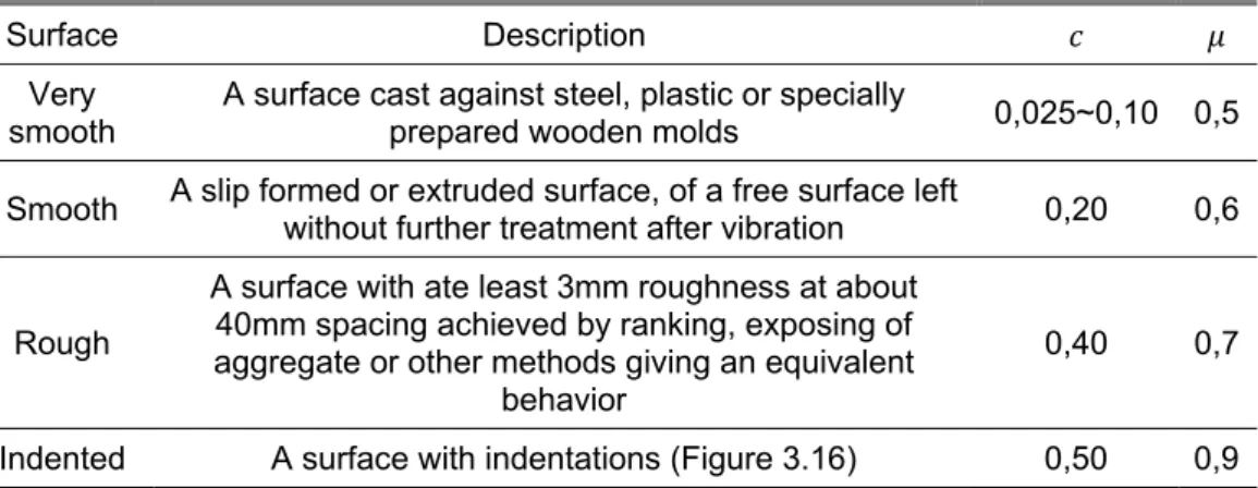
Table 3.4: Roughness parameters for Expression 3.3, adapted from EC2 ... 31
Table 3.5: Coefficients for the determination of interface shear strength (adapted from MC2010 tables 7.3-1 and the table in section 6.3.2) ... 32
Table 3.6: Coefficient for surface roughness in interfaces crossed with dowels, adapted from MC2010 ... 33
Table 3.7: Properties of the concrete overlay ... 38
Table 3.8: Concrete removal methods, adapted from Rilem, (2011)... 41
Table 3.9: Laboratory tests: influence of microcracking, adapted from Rilem, (2011) 42 Table 3.10: Beam characteristics, adapted from Santos, Shehata & Shehata (2007) 57 Table 3.11: Strengthened beams, adapted from Santos, Shehata & Shehata (2007) 57 Table 4.1: Substrate reinforcement ... 68
Table 4.2: Model I – overlay reinforcement ... 70
Table 4.3: Model II – overlay reinforcement ... 70
Table 4.4: Model III – overlay reinforcement ... 71
Table 4.5: Mechanical properties ... 79
Table 4.6: Stress characteristics for concrete ... 81
Table 4.7: Compressive strength for the cylindrical specimens (concrete used in overlays of SMII and SMIII) ... 82
Table 4.8: Grout properties provided by the manufacturer ... 82
Table 4.11: Resistance of a single dowel ( ) and of the interface ( , ) ... 85 Table 5.1: Determination of the height of the neutral axis, steel and concrete stress114 Table 5.2: Determination of experimental interface shear stress by Equation 5.1 .... 115 Table 5.3: Determination of , 2 ... 115 Table 5.4: Determination of , 3 ... 115 Table 5.5: Predicted shear resistance (Walraven’s sphere model) ... 116 Table 5.6: Predicted shear resistance (EC2 Equation 3.21, MC2010 Equation 3.23) ... 116 Table 5.7: Predicted shear resistance (interfaces connected by dowels – MC2010) 117 Table 5.8: Comparisons between experimental and predicted values ( , 1) ... 118 Table 5.9: Comparisons between experimental and predicted values ( , 2) ... 118 Table 5.10: Coefficient and degree of the polynomial ... 119 Table 5.11: Experimental cracking loads, and moments , ... 121 Table 5.12: Predicted cracking moments and forces ... 123 Table 5.13: Predicted cracking forces ... 123 Table 5.14: Comparison between experimental and predicted cracking loads ... 124 Table 5.15: Homogeinity coefficients ... 125 Table 5.16: Average increase in flexural resistance, provided by reinforcement crossing the interface ... 126 Table A.1: Average roughness (Beam I.A)……….…..………...…………..…………137
Notations
Meaning of Roman capital letters: area
area of the interface area of reinforcement
, area of reinforcement crossing the interface
elasticity modulus applied load steel force moment of inertia moment
normal force reaction, roughness average roughness mean to peak valley height
shear force
Meaning of roman lower case letters: width
width of the interface cohesion
effective depth to main tension reinforcement or the diameter of the hole shear flow
cylinder compressive strength of concrete mean axial tensile strength
, cubic compressive strength of concrete , mean value of compressive strength ,
design value of characteristic value of
yield stress of non-prestressing reinforcement
length of the interface slip
, design value for shear stress in the interface
interface shear stress
, design limit value for interface shear
crack width
height of the compression zone internal lever arm
Meaning of Greek lower case letters: angle or coefficient for dowel action
ratio of the longitudinal force in the new concrete and the total longitudinal force
safety factor
safety factor for concrete homogeneity coefficient safety factor for steel strain
concrete strain steel strain
coefficient for tensile force activated in the reinforcement or dowel friction coefficient
ratio of reinforcement crossing the interface normal stress
shear stress
Introduction
1.1 Background
Over the last century, with the continuous proliferation of concrete in construction, the need to repair, strengthen and adapt structures to new loads is increasing (Clímaco & Regan, 2001). Repair actions involve re-establishing the strength and function of damaged elements whereas strengthening consists of upgrading the strength or stiffness of structural elements.
Structural problems can be the result of several factors, such as: project or execution errors; structure’s misuse (when elements are subjected to loads different from the designed); quality of materials and deterioration agents. These factors can ultimately lead to structural failure. However, before failure, usually some symptoms are displayed, for instance large deformations or excessive cracking. At this point retrofitting actions may be considered. It is important to make an assessment of the actual condition of the structure and the eventual damage or degradation causes. Most procedures involved in rehabilitation require expert materials, techniques and knowledge, making rehabilitation a complex task (Garcia & Clímaco, 2001). To reduce the cost of an intervention, it is possible to use traditional materials and methods (Pires, 2003).
A widely used strengthening technique that uses traditional materials consists of placing a new concrete layer at the top or the underside of an existing RC element. The most usual procedure is to increase the compression zone. Reinforcement may, or not, be embedded in the new concrete layer. This technique implies either an increase in the elements dimensions and weight or, if the goal is to maintain the geometry of the section, the surface must be partially demolished.
When strengthening a slab or beam with a new concrete layer, flexural strength can be improved either by an increase in the compression zone (and the inner lever arm), or by an increase in the tension zone with addition of steel reinforcement.
However, the bond between the differently aged concretes presents a weak link in the composite structure, and the success of the intervention relies on the interface capacity to transmit stresses and ensure monolithic behavior. Shear stresses and strength along the interface has been the object of studies by numerous authors, and the subject has continuously been revised over the years (Beushausen & Alexander, 2007; Moyamez et al. 2002; Santos & Julio, 2010). Even MC2010 presents a much more thorough approach than provisions in MC90 and EC2. Some of the new aspects present in MC2010 are a quantitative evaluation of roughness, differential shrinkage and edge reinforcement.
addition of tensioned steel reinforcement embedded in the new concrete layer. The element may need a thickness enlargement, or the substrate concrete might be partially demolished and the new concrete poured to the previous height. The latter technique was recently used in building Visconde de Alvalade, Lisbon. The structural strengthening was designed by VERSOR, Lda.
Figure 1.1: Cracking pattern around the columns (Building Visconde de Alvalade)
Figure 1.2: Reinforced concrete overlay (Building Visconde de Alvalade)
This technique is suitable for large intervention areas, such as buildings slabs or bridge decks, where increasing the compression zone is not possible (Keesom et al., 2008). One of the shortcomings inherent to this type of strengthening intervention is the difficulty in respecting the anchorage lengths of the new reinforcement.
The design methodology adopted when repairing a structure with a new concrete layer might be relate to a precast element which receives in situ topping, as both should consider stress transfer across the interface (MC2010).
1.2 Developed work
This dissertation presents a study about RC overlays in the tension zone as a strengthening solution that is expected to increase the flexural capacity of RC slabs or beams. As mentioned, the success of this technique relies on the interface capacity to transmit stresses between the new and old concrete layers. Stress transfer is dependent on a number of factors, in particular, adhesion between concretes, roughness, the amount of reinforcement crossing the interface and the location of the same reinforcement.
In this dissertation, an experimental research was conducted on large scale strengthened beams. Specifically for this purpose, nine beams were created and later strengthened at a precast plant. The beams were subjected to three point bending tests. Cores were also drilled to perform pull-off tests, which would allow for knowledge of the bond’s behavior under both tensile and field stresses.
The development of such beams was related to the fact that the problem would be easier to understand if it was isolated in only one direction. The beams had enough transversal reinforcement, therefore forcing a failure mode related to the interface capacity to transmit stress and, also, related to how much of the flexural resistance of an equivalent monolithic cross-section is activated.
The substrate beams were designed with interrupted longitudinal reinforcement at midspan, which created a deficit in flexural resistance. To correct this situation, the beams were then strengthened by means of a RC overlay in the tension zone. Prior to the overlay placement, the substrate surface was roughened with jackhammers. The strengthened beams were designed to resist high bending and shear loads, in such a way that the interface shear stress, necessary to mobilize all flexural resistance, would be very high. Therefore, as mentioned, interfacial failure was expected, when the composite specimens were subjected to bending tests, allowing for a quantification of ultimate shear stress.
Three different situations were considered regarding stress transmission across the interface (described in Table 1.1). The first solution (SMI) was developed to quantify bond strength between the two concrete layers. Strengthening models with solutions II and III were used to analyze contribution of reinforcement crossing the interface for shear resistance and the influence of the location of the same reinforcement. Each of the mentioned strengthening solution consisted on three specimens.
Table 1.1: Strengthening models (SM)
SMI
Shear transmission between concrete layers relies only on the concrete-to-concrete capacity to transmit stresses. For an interfacial failure, bond strength in a combined state of shear and tension can be determined.
SMII
Dowels anchored in the substrate cross the interface with the intent of increasing ultimate shear strength. For a failure in the interface plane, ultimate shear strength can be determined.
SMIII
The length of the new reinforcement bars is higher than in the previous models, and the rebars are bent into an L shape, crossing the interface and anchored in the substrate, near the end of the overlay. In case of failure across the interface, ultimate shear strength can be determined. Structural behavior is reported in terms of: steel strains, deflections, cracking behavior, ultimate load, failure modes. Adhesive strength was to be determined by the pull-off test.
This study is a part of the investigation project, funded by the “Fundação para a Ciência e Tecnologia”, PTDC/ECM/114492/2009 – FLAT – Behavior or flat slabs under cyclic and seismic loads.
1.3 Objectives
The objective of this dissertation is to increase knowledge about RC overlays in the tension zone, as a flexural strengthening solution. Moreover, this dissertation intends to characterize the load bearing behavior of strengthened beams, the resistance of the interface and help to understand specifically the contribution of reinforcement crossing the interface.
Regarding the contribution of reinforcement crossing the interface, the location and amount of steel reinforcement differ for each of the three beam models. The overall resistance and its relation with the location of the mentioned reinforcement is also investigated in the present dissertation.
Analyzing the different cracking behaviors, the evolution in vertical deflections of each specimen and relating the obtained results with the properties or pre-existing conditions of each beam is also a goal for this dissertation.
From the obtained results it is possible to evaluate the effectiveness of each solution. Furthermore, results obtained in the different tests are compared among each other, with the provisions from MC2010 and EC2, and other predictions encountered in literature about this subject.
Another goal for this dissertation was to determine bond strength under tensile stress, and compare it with the results obtained from the beam tests. However, due to difficulties regarding the execution of the pull-off tests, it was not possible to advance with this objective.
1.4 Organization
This dissertation is organized in six chapters and two appendixes, comprising an introduction and a conclusion, a contextualization about different strengthening solutions, state of the art about interfaces between differently aged concretes, experimental program, test results and discussion.
Chapter two provides an overview of different strengthening solutions, emphasizing the problematics of interfaces between different materials used in concrete rehabilitation. In chapter three, the actual state of knowledge on RC overlays, particularly in the case where the strengthening provides an increase in steel force (by adding additional reinforcement) is briefly described. Stress state at the interface is explained, as well as approaches to shear resistance. Research conducted on the theme allowed for an identification of the main factors that can influence adhesion and ultimate shear stress.
Chapters four and five cover the experimental research, the first provides a characterization of the tested specimens and laboratory test setup, as well as the behavior expected for each model. In Chapter five test results are displayed and the different behaviors of the composite beams are analyzed.
Chapter six presents final remarks and a brief summary, regarding test results and their analysis, as well as suggestions for future research.
Repair and strengthening of RC
elements
2.1 Introduction
Rehabilitation of RC structures is an issue that has been addressed worldwide. A rehabilitation project should begin with an assessment of structural conditions, the choice of materials and the development of a strengthening solution. For each condition encountered in the field, one strengthening solution may be preferred to another, and as always, engineering judgment is required.
In this chapter concrete rehabilitation is outlined, and particular emphasis is given to flexural strengthening of horizontal elements. The performance of the bond between substrate and repair materials is also given special attention.
2.2 Materials
An important concern associated with strengthening and repair actions is the careful selection of materials. Although technological developments have introduced innovative materials, which are increasing importance in the rehabilitation field (Rodrigues, 2005), traditional construction materials are still viable options.
These materials should have as characteristics: low permeability, durability, good adherence to concrete and steel, good structural resistance, low shrinkage and workability, easiness of application and compatible properties with concrete and steel (Santos, Shehata & Shehata, 2007).
Most common repair and strengthening solutions involve the utilization of: cementitous materials
(polymer) modified cementitous materials composite materials
epoxy resins
addition of steel plates/rebars introduction of prestress
2.2.1 Cementitious materials
Projecting concrete (shotcrete) is a common method used when placing a new concrete layer in the underside of a slab. Using a cast and pouring the concrete, not to mention the vibration of the same concrete, would be otherwise too complicated to execute in this case. Self-compacting concrete is also usually employed in places where concrete vibration is complicated, or when it is necessary to pour concrete into a large area with small thickness.
2.2.1.1 Shotcrete
Shotcrete is defined as “mortar or concrete pneumatically projected at high speed onto a surface”. There are two basic types of shotcrete – dry mix and wet mix. In dry mix shotcrete, the dry cement, sand and coarse aggregate, if used, are premixed only with sufficient water to reduce dusting. This mixture is then forced through a delivery line to the nozzle by compressed air. At the nozzle, sufficient water is added to the moving stream to meet the requirement of cement hydration. For wet mix shotcrete, the cement, sand and coarse aggregate are first mixed in water and the resulting concrete is then pumped to the nozzle with compressed air (Smoak, 2004).
2.2.1.2 Self-compacting concrete
Self-compacting concrete is able to flow when placed in a cast, covering and passing through the reinforcement (Pereira & Barros, 2004). The cast is filled by the effect of the concrete’s self-weight, requiring little or no vibration. This type of concrete is particularly suitable for regions of difficult vibration, which is often the case with strengthening procedures.
Technological evolution in chemical admixtures, especially in what concerns super plasticizers, have endowed a fluid behavior to concrete in the fresh state.
The highly flowable nature is also the result of a careful mix proportion with continuously graded powder; much of the coarse aggregate is replaced by fine aggregate, cement and chemical admixtures (Figure 2.1). Concrete in the fresh state can be divided into a solid (aggregate) and fluid component (cement paste/binder), which combines cement, admixtures and water. The suspension particles in the fluid component have the tendency to form flakes that have larger equivalent diameters than the particles that compose them, reducing the fluidity of the paste and requiring more water to achieve the same fluidity. Super plasticizers disperse these particles, avoiding the segregation which favors the interaction and results in higher stability and better rheological performance. This allows concrete’s water cement ratio to be kept at low value and still provides fluidity and workability.
Figure 2.1: Self-compacting concrete (SCC) and normal concrete (NC) mix proportion, adapted from Gonçalves (2007)
coarse aggregate sand
cement water admixtures
2.3 Strengthening Techniques
2.3.1 Addition of new concrete layers
This technique involves adding a bonded concrete layer to an existing RC element. It is appropriate to strengthen columns, slabs and beams. As an outcome of this strengthening solution, the element’s cross-section might be enlarged, so when it is necessary to increase the concrete compressive strength, or control deformations this solution can be especially appropriate.
One of the shortcomings of applying new reinforced concrete layers is that it might introduce new weight to the structure, and require the adaptation of other structural elements (such as beams and columns).
The procedures related to this technique require lowering the structural element loads to a minimum and reducing stresses in the intervened elements. Part of the load and the weight of the elements should be directed to shoring in order to proceed with the strengthening intervention (Rodrigues, 2005).
After shoring is installed, the concrete surface must be prepared to ensure good bond with the new layer. Then, if necessary, new reinforcement and formwork may be positioned. Provided that the surface is cleaned, the new concrete can be cast or projected onto the surface. To avoid possible cracking due to shrinkage, it is necessary to ensure a moist environment during the curing process (Rodrigues, 2005).
2.3.1.1 Horizontal elements
Bonded concrete layers may be applied onto the element’s top or lower surface. If the layer is to be applied to the top surface, then concrete may be simply poured on top, whereas for the underside, shotcrete is usually preferred. As mentioned in section 1.1, this can be done by an enlargement in the element’s cross-section. However, in some cases it is possible to maintain the previous thickness by demolishing a layer in the substrate concrete. Decisions about increasing the element dimensions or introducing extra reinforcement, as all decisions regarding strengthening procedures, are determined by many variables that differ with each case. Reasons for choosing one over the other may be:
The geometry of the RC member. A small thickness may lead to high deflections, and in this case it would be most suitable to increase the cross section, probably with an increase the compression zone (if it’s demonstrated that enough longitudinal reinforcement is present).
Eventual corrosion, lack of reinforcement, or misplaced reinforcement may require the introduction of new reinforcement. In this case the element’s thickness may be maintained.
Interventions may only be performed on one of the surfaces of the slab. For instance, if the goal is to increase flexural strength for negative bending moments, an increase on the slab’s height (applying the new layer to the underside), would be a possible solution. But in some cases, it might not be possible to act on this side, so a reinforced concrete overlay onto the top surface may present a valid alternative.
Figure 2.2 illustrates two examples of flexural strengthening for negative bending moments in the tension, and compression zone. In both cases, punching shear resistance also increases, either because there is an increase in the elements thickness, or in the reinforcement ratio.
Figure 2.2: Flexural strengthening of a RC flat slab for negative bending moments in the tension (a) and compression (b) zone
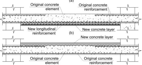
If the goal is to increase positive bending moments, a RC overlay in the compression side might be a possibility. Strengthening the tension side is also an option. Both this strengthening solutions are schematized in Figure 2.3.
Figure 2.3: Flexural strengthening of a RC flat slab for positive bending moments in the tension (a) and compression (b) zone
Original longitudinal reinforcement New concrete layer New longitudinal
reinforcement
Original concrete element
Original concrete element
Original longitudinal reinforcement
New concrete layer (a)
(b)
(b) (a)
New concrete layer New concrete layer Original concrete
element
Original concrete element New longitudinal
reinforcement
Original concrete reinforcement
2.3.2 Addition of steel plates
A common technique for increasing the flexural capacity of a reinforced concrete element is to add steel plates glued with an epoxy resin, with the eventual help of bolts or post-installed anchors.
The steel plate installation is rather easy. However overlapping plates may present some difficulties, therefore this method works best when strengthening is required in only one direction. Another disadvantage of this system is that when applied to the top of a slab, it might interfere with the flooring system (Banu & Taranu, 2010).
This technique is most suitable to increase flexural strength in the situation of insufficient reinforcement. The quality of concrete and cross-section dimensions must ensure the necessary resistance, avoiding excessive deformation.
The interface between the steel plate and the concrete element may also experience debonding. To increase shear strength, connectors are usually placed.
2.3.3 Addition of carbon fibers
FRP sheets and glass fibers are commonly used to strengthen structures because of their high resistance to tensile stress. The fibers work as reinforcement attached to the concrete element, providing extra tensile resistance. The elements geometry maintains almost unaltered. This solution is viable when the dimensions of the concrete element are sufficient to resist compressions, but steel reinforcement is insufficient.
The main problem with this strengthening procedure is the fact that bond relies solely on adherence mechanisms, and no connectors cross the interface. Therefore this solution is especially exposed to the possibility of interfacial failure.
2.3.3.1 Debonding phenomena in the case of structures retrofitted with FRP sheets
A RC beam strengthened with a bonded FRP plate should fail, ideally, either by concrete crushing in the compression zone or a tensile rupture in the FRP plate. However, in most cases, the cause of failure is related with debonding of the FRP plate from the RC beam (Yao & Teng, 2007).
Debonding between the FRP plate and concrete may occur in one of several possible modes. In Figure 2.4 (a), a situation where debonding initiates at a flexural or flexural-shear crack in the high moment region and propagate towards one of the plate’s ends is represented. This debonding failure mode is referred as intermediate crack (IC) debonding.
There are a number of factors can influence the probability of a particular debonding failure mode, for instance the distance from the plate to the supports and the dimensions of the same plate.
Figure 2.4: Debonding failure modes of a plated RC beam (Yao & Teng, 2007)
2.3.4 External post-tensioning
This method is very effective in increasing flexural and shear capacity of concrete elements, with minimum additional loads to other structural elements (Banu & Taranu, 2010). The post tensioning forces are delivered to the structure at anchor points of prestressing tendons or high-strength steel rods. Prestress can be considered as an imposed deformation or equivalent forces
This technique has been used successfully in bridge rehabilitation.
2.3.5 Altering the structure
It is always possible to alter the structure, introducing new vertical and horizontal elements, such as columns and beams, which allow for loads redistribution and relief from stresses on the initial structure. However, this type of strengthening solution modifies significantly the interior space and may impose limitations in terms of the normal use of the building. Also, this solution may expend a significant amount of material, increasing the cost of the intervention.
2.4 Repairing techniques
2.4.1 Crack repairing
Crack repairing should only be performed once the cause of cracking has been determined and the necessary steps have been taken to avoid recurrence. A crack gage installed across a crack will allow determination of widening or movements of the crack, and regulate whether or not the crack is active (Figure 2.5). With crack repairing the original flexural stiffness may be restored to the RC element, but flexural strength in relation to the initial situation won’t be improved (The Concrete Society, 1984; Rodrigues, 2005).
It is recommended to use an epoxy resin to seal cracks with widths from 0,1 to 5mm. For larger cracks, grout can be applied. In water retaining structures it is common to use polyurethane to seal the cracks (Smoak, 2004).
The following steps can be used in crack repairing: Cleaning the intervention area
Widening and enlargement of the crack
Cleaning the crack, removing loose material. Smoak (2004) suggests cycles of compressed air, followed by water. Using a steel brush is also a possibility. Injecting resin or grout.
Figure 2.5: Crack gage installed across a concrete crack (Smoak, 2004)
2.5
Practical examples of reinforced bonded concrete
overlays
2.5.1 Building
Visconde de Alvalade
The Visconde de Alvalade is an office building in Lisbon with eight floors, and three underground garages. It was built in 2003, and subjected to a strengthening intervention in two of the underground garage slabs in 2011.
2.5.1.1 Causes and extent of degradation
Table 2.1: Crack width
Type of Cracking Crack width
Flexural cracks near the columns w>0,4mm Flexural cracks between columns w<0,4mm
Shrinkage cracks w>0,3mm
To investigate the cause of cracking, the position and quantity of the reinforcement was surveyed, using a pacometer and two investigation cores (Figure 2.6).It became clear that, although the top reinforcement was present, it had been misplaced, at a lower vertical position and covers measured in average 95mm instead of the 25mm specified in the building’s project.
The flexural capacity of the slabs was reduced by 40% in relation to the project. Despite the fact that no circumferential cracks were visible around the columns, the punching resistance of the slabs was reduced by 62%.
Figure 2.6: Core extracted from the slab in -2 level (while the thickness is 0,28m, the concrete cover of the top reinforcement measures 0,1m)
2.5.1.2 Strengthening procedures
The slabs were strengthened by the addition of a new concrete layer. In this case, the two possible solutions illustrated in Figure 2.2 could be effective in increasing flexural strength. However, strengthening the slab by an increase in the compression zone, near the column, presented a problem, since the buildings infrastructures circulated under the ceiling. These infrastructures were necessary because the other floors of the building would maintain normal use during the strengthening intervention.
The intervention intended to improve both flexural strength for negative bending moments, and punching shear strength with the addition of flexural and punching reinforcement. A thin reinforced concrete layer was poured into a limited area that had been previously demolished on the top surface the slab around the columns, thus making it possible to maintain the original height (Figure 2.7). The shrinkage cracks and remaining flexural cracks were filled with epoxy injections. Because the slab’s dimensions were maintained, there was no significant addition in loads to other structural elements.
along the intervention area. Some longitudinal reinforcement was also anchored in holes previously drilled in the substrate.
The following procedure was adopted:
Shoring of the two damaged slabs, and measuring eventual displacements with a deflectometer;
Demolition of the concrete cover before reaching either the substrate reinforcement or a maximum depth of 80mm. The demolition area corresponded approximately to 1/4 of the span, around each column;
Repairing the remaining cracks;
Vertical perforation of the slab, in order to place new punching reinforcement, shear connectors and anchor longitudinal bars (Figure 2.8 and Figure 2.9); Placement of the reinforcement;
Injection of cement grout and epoxy resin, sealing holes;
Pouring the new concrete: a self-compacting concrete was adopted;
Figure 2.7: Longitudinal and punching shear reinforcement
Figure 2.8: Shear connectors crossing the
interface
Figure 2.9: Anchorage of the longitudinal reinforcement
2.5.2 Prestressed viaducts in the Netherlands
According to Keesom et al. (2008) seven viaducts in the Dutch highway, A9, built around 1970 have experienced increasing traffic loads. Therefore, it was necessary, either to recalculate the structure for the present standard traffic standards, and prove that either it would maintain, at least, 15 more years of life, or strengthening the viaducts would be necessary. If strengthening revealed to be necessary, it should ensure a surplus life of at least 100 years. Although there were no visible signs of degradation, the present day loads were superior to the designed ones, and an assessment of actual load bearing capacity was required.
The viaducts are built using prestressed girders and a reinforced cast-in-place deck. The cast in place deck was designed to resist negative bending moments at the supports, caused by the statically undetermined system.
The structural dimensions and the steel disposal were obtained from as-built drawings. Cores were drilled on the deck to determine both compressive and tensile strength of the concrete. For this purpose, compressive, direct tension and splitting tests were executed.
After assessment of the actual conditions of the viaduct, the slab was modeled in a FEM program. It was concluded that four of the seven bridges needed structural strengthening, because there was insufficient reinforcement near the supports and insufficient transversal reinforcement in the cast-in-place deck, and the girders were under high tension stresses at midspan. The solution consisted of the application of an approximately 100 mm reinforced concrete overlay.
In this case, strengthening the underside of the slab was impossible due to its geometry.
The client had imposed some specifications regarding the concrete overlay. A concrete grade of C53/65 was defined, as well as minimum bond strength of 1,5N/mm2. It was required that concrete covers measured at least 40mm. In addition, across the interface, steel anchors were to be placed, at least 4 per m2 and near the edges 10 per m2. FEM results showed that in the middle of the overlay anchors were not necessary, because the adhesion between layers was more than sufficient to assure bonding. However near the edges, the authors state that anchors were required due to stresses caused by drying shrinkage of the overlay.
The overlay increased the loads transmitted to the base of the piles in 10%. The designers considered that the foundations should resist the increase in loading due to the use of relatively large scale factors.
Another specification of this project was that, six days after casting, the overlay had to be ready for use. A trial casting was preformed, and the strength development was documented and verified. After only six days, a bond strength of 1,5MPa was achieved. The interface surface was roughened resorting to milling.
After milling, some top reinforcement became visible and it was verified that the actual dimension of the slab was inferior to the predicted. Therefore it became necessary to increase the height of the new concrete layer. After milling, holes were drilled in the substrate to anchor the connectors. The longitudinal reinforcement used was prefabricated.
State of the art
3.1 Introduction
The addition of a new concrete layer bonded to an existing RC element can provide substantial enhancement in flexural resistance. Nevertheless, concrete-to-concrete load transfer across interfaces can lead to premature failure of the composite element. Therefore, strains and stress state at the interface, adhesive bond strength and ultimate shear stress must be quantified in terms of variables that can influence their values.
In this chapter, the stress state at the interface and the main factors that can influence stress transmission between concrete layers cast against each other with different ages, particularly in the case of bonded concrete overlays, are described based on literature about this subject and provisions of EC2 and MC2010.
Moreover, when analyzing bonded concrete layers, it is important to consider the fact that when a new concrete layer is placed, the substrate has already experienced most of its drying shrinkage, thus restraining free deformation of the RC overlay and inducing stresses (which reach maximum values at the interface perimeter).
Another problem associated with this strengthening solution is related to the fact that when the new concrete layer is placed, on site, it is difficult to provide a clean interface surface. Contamination of interface surfaces causes a negative impact on adherence between concretes. Good practices regarding the execution of bonded concrete overlays are also mentioned.
3.2 Bond strength and shear strength at the interface
Bond or adhesion between substrate and overlay is regarded as the way in which these materials can act together, before a crack along the interface is formed.
If the resistance of an interface is assured only by adhesion, it is commonly designated as bond strength. Providing good bonding is a key factor to ensure monolithic behavior and the effectiveness of the strengthening intervention. In literature, several studies have proven that there are a number of factors that can influence bonding, such as cleanliness and roughness of the interface.
Adhesive bond can be enhanced by optimizing fresh concrete properties and roughening of the substrate surface. However, the adhesive component is yet to be completely defined. Roughness and concrete compressive (or tensile) strength are the main parameters used to describe adhesion; other factors that can influence adhesive bond, (e.g. drying shrinkage and w/c ratio) are often neglected. However, as adhesion is quite dependent on the cleanliness of the substrate, on site, a contamination scenario must not be ignored.
Values for adhesion/shear strength are highly dependent on the test measuring procedure, as they are related to stress state of the interface. Bond strength is usually defined as the tensile strength perpendicular to the interface plane and can be determined by pull-off tests (Rilem, 2011). Bond strength in shear has also been considered by several authors, as it is associated to stress states typically found in the field (Bakhsh, 2010).
Often, the adhesion strength between concrete layers is not sufficient to resist interface stresses, requiring the designer to allow for a cracked interface and place reinforcement across both concrete layers. In this case, adhesive bonding can be exceeded (if reinforcement is able to sustain the increase of stress resultant from loss of adhesion). Therefore, it is important to determine both the shear strength at the interface and adhesion strength and guarantee that rupture is not characterized by this weakness plane.
In addition, as adhesive bond is associated with brittle behavior, a certain amount of reinforcement crossing the interface is required. For economic reasons the goal is to take the most advantage of adhesive bonding, and minimize the reinforcement area (Randl, 2011).
According to MC2010, representative mean values for the mean shear resistance vary in the following ranges:
Table 3.1: Representative mean values for the mean shear resistance (MPa)
Rough interface (e. g. sandblasted) 1,5~2,5 Very rough interface (e. g. high pressure watter jetted) 2,5~3,5
3.3 Test methods
The values obtained for bond/shear strength are highly dependent on the stress state at the interface and the test measuring procedure. The tested elements will obviously react differently if the interface is subjected to tension, compression, shear or torsion. Experiments may be performed with large or small scale specimens.
According to Randl and Zilch (2009) large scale specimens reflect the real situation in the structure somewhat better, but small specimens allow for a more precise understanding of the interface stress and a larger number of tests. MC2010 considers the main parameters that influence load bearing capacity observed in tests to be interface roughness, cleanliness, concrete strength and quality, eccentricity/inclination of shear force, strong bond, pre-cracking or debonding before testing and the ratio of reinforcement crossing the interface.
3.3.1 Large scale tests
3.3.1.1 Flexural tests
Three and four point bending tests are commonly used in experimental research about strengthened beams. Strengthened slabs have also been subjected to bending tests, however, conducted experiments encountered in literature (Pires, 2006; Santos, Júlio & Silva. 2007) are not tests specifically on shear resistance, but on the overall performance of the strengthening solution.
3.3.1.2 Punching shear tests
As an addition in the elements dimensions and steel ratio may lead to an increase in punching shear capacity, punching shear tests may be performed on slabs. Datta and Seraj (2003) studied precisely the effect of a bonded concrete overlay in the punching shear capacity of slabs. The study concluded that punching shear can significantly be increased by this strengthening method, and dowels have a positive effect.
3.3.2 Small scale tests
A number of small scale tests have been developed, and are mostly used to determine interface bond strength.
Tests may be classified in relation to the stress state they impose to the interface. In tension, most popular bond tests are splitting prism and direct tension tests (Figure 3.1), the latter can be carried out in laboratory or in-situ. In the splitting test a prism with a circular or squared cross-section is placed under longitudinal compressive load. Shear tests usually apply the force in the direction of the interface (Figure 3.2). Modified shear tests, such as the slant shear test are also widely used.
To analyze the effect of reinforcement crossing the interface, push-off tests have been used.
Figure 3.1: Tension tests, (a) Direct tension (b) and (c) Splitting prism, adapted from Rilem (2011)
Figure 3.2: Shear tests, (a) Common shear tests and (b) Shear test applying torsion, adapted from Rilem (2011)
(a) (b) (c)
3.3.2.1 Pull-off test
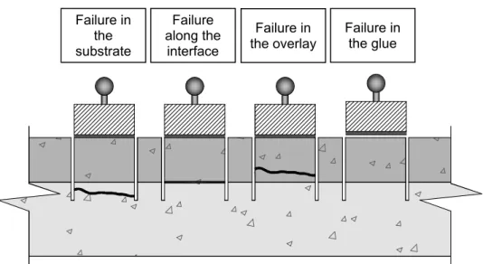
The pull-off test is a simple direct tension test that can be useful when evaluating bond strength and failure modes between new and original concretes, both in laboratory and on site conditions. The test usually requires partial coring of the composite elements; at least 10mm bellow the interface. A load frame is glued to the surface of the core through a metallic disc and the element is then loaded, subjecting overlay material, the interface and part of the substrate to the tensile load, . The pull-off strength,
,
can easily be determined by Equation 3.1. Failure modes are described in Figure 3.4. This test presents the disadvantage of being sensitive to eccentricities (Ramezianpour et al., 2007).⁄
(3.1)Where,
is the area of the interface
Figure 3.3: Pull-off test setup, adapted from Borges (2008)
Figure 3.4: Typical pull-off failure modes, adapted from Borges (2008)
Loading device
Core drilled at least 10mm beyond the interface
Tes disc Epoxy glue
Failure in the substrate
Failure along the
interface
Failure in the overlay
A failure in the interface (adhesive failure) indicates bond strength. It is also possible that an interfacial failure is combined with partial substrate failure, which can be the result of, for instance, micro cracks in the substrate. When substrate or repair material failures (cohesive failures) occur, the ultimate strength represents a low estimate of the tensile strength. Results should not be considered when the disc detaches from the core. Failure might also take place while drilling the cores.
Values for pull-off strength are most dependent on the diameter and depth of the core (Rilem, 2011). The related standard methods for the pull-off test are found in EN1504-3. The European procedure requires at least a surface cohesion value of 2MPa for structural repairs, and 5 valid tests.
3.3.2.2 Slant shear test
This test was primarily used to evaluate bond strength of resinous materials and bonding agents in a stress state that combines shear and compression. Some authors have found this test to be particularly sensitive to roughness, and have used it to evaluate bonding between different age concretes.
The test consists on subjecting a composite prism or a core of substrate and repair material that has a joint at an accurate angle, to axial compression. The interface stress state combines shear and compression. It presents the advantage of being easy to perform, as it can be tested in a compression machine. Results are reproducible and sensitive to roughness (Garcia & Clímaco, 2001). The bond strength measured depends of the angle of the interface and rupture occurs at different compressive stresses for different angles. The correct interface angle must be used in order to obtain significant results.
Figure 3.5: Slant shear test, adapted from Clímaco and Regan (2001)
Failure can occur either at the interface, at a plane near the interface or be monolithic. According to Clímaco and Regan (2001), if the bond is effective, failure is characterized by a rupture in concrete, and the joint is subjected to an uneven combination of shear.
(3.2) The cohesion, , represents the interception of the straight line with the shear axis. The friction coefficient, , is dependent on roughness.
From the equilibrium between the applied force and stresses at the interface (Figure 3.5), it is possible to determine both normal and shear stresses at the interfaced, given by Equations 3.3 and 3.4.
(3.3) (3.4) From Equations 3.2-3.4, it is possible to determine the compressive strength of the prism, , when failure is governed by the weak plane:
1
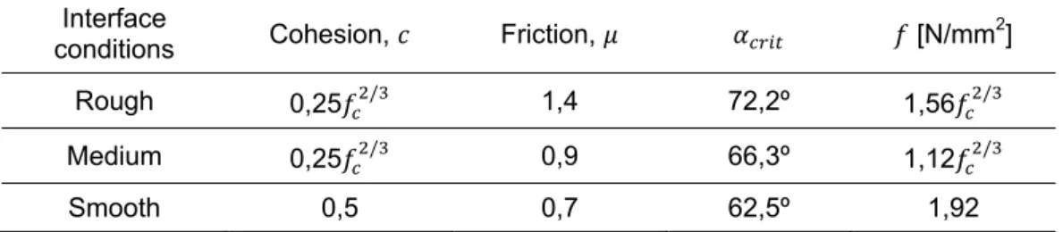
(3.5) As cohesion and friction are dependent on parameters such as surface treatment and joint angle, it becomes complicated to describe the most critical angle. Table 3.2 provides values for and from a study elaborated by Clímaco and Regan (2001).
Table 3.2: Critical joint angles and minimum compressive strength of prisms adapted from Clímaco and Regan, (2001)
Interface
conditions Cohesion, Friction, [N/mm
2 ]
Rough 0,25 / 1,4 72,2º 1,56 /
Medium 0,25 / 0,9 66,3º 1,12 /
Smooth 0,5 0,7 62,5º 1,92
Where,
is the cylinder compressive strength of concrete
is the compressive strength of the composite prism, when failure is governed by the weak plane
3.3.2.3 Push off test
With the push off test the shear resistance of an interface connected by dowels can be determined. It is used to analyze precisely the effect of dowels perpendicular to the interface plane (Figure 3.7). The relation between shear stress and the applied force is related to the interface dimensions, and ⁄ , being is the width of the interface.
Figure 3.7: Push off test, adapted from Walraven et al., 1987
3.4 Shear stress at the interface
In classic mechanics, when a beam composed of two different materials is subjected to load along the (2) axis, two limit situations may be considered (Figure 3.8). Situation (a) represents a scenario where both materials act together. In situation (b), materials act separately, creating a relative slip between them. Example (a) is also true in the case of beams composed by only one material: as no slip between horizontal planes takes place, the material act together, inducing shear stress in any horizontal plane.
Figure 3.8: Limit situations for stress transfer across an interface (a) undeformed composite beam (b) materials act together (c) materials act separatly
In a system composed of two concrete layers, which is obviously the case of an element strengthened with a concrete overlay, it is important to resist these horizontal shear forces and ensure composite action, with minimal slip between substrate and overlay.
The stress transfer across a concrete-to-concrete interface is considered to occur by adherence, dowel action in the transversal reinforcement (crossing the interface), friction and tension in the transversal reinforcement triggered by aggregate interlock.
3.4.1 Determination of shear stress in the interface
Since an original RC element has probably endured a certain amount of stress prior to the strengthening intervention, the strain distribution on the cross-section of the composite element is not continuous. Strain distribution is also dependent on interface slip. Therefore, usual bending and shear theories might not be valid in the case of strengthened elements.
There are some concerns as to whether or not the assumption of linear strain distribution in a concrete composite cross-section is valid, namely because of concrete cracking and flexibility of the shear connectors (Dritsos et al., 1995). Another issue addressed by Beushausen and Alexander (2007), is related to the fact that strains resulting from restrained shrinkage of the overlay should also be considered in the design.
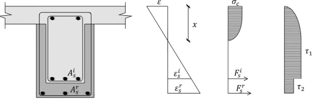
In Figure 3.9, possible normal strain and stress distributions for concrete overlays in the tension zone are exemplified.
(a)
(b)